IJEDR1602276
International Journal of Engineering Development and Research (www.ijedr.org)1542
Computational Static and Dynamic Analysis of
Sandwich Panel (Aluminium 2024 + Si3N4)
1
Karthik G,
2Raghu Tilak Reddy.M,
3Chethan K.Y
1PG Student,2Assistant Professor,3Assistant Professor 1Department of Mechanical Engineering,
1New Horizon College of Engineering, Bangalore – 560103 3Vemana Institute of Technology, Bangalore –560034
________________________________________________________________________________________________________ Abstract - Utilization of Sandwich development for an airplane structural component is exceptionally regular to the present day. One of the essential requirements of aerospace auxiliary materials is that they ought to have low thickness, firm and solid. Sandwich boards are slight walled structures fabricated from two level sheets separated by a low thickness center. The center researched here is of Aluminium20245alloy honeycomb structure due to superb smash quality and exhaustion resistance. Sandwich panels have a high firmness to weight proportion with deference equal strong plate in light of low thickness center. Displaying is created in FEA (ANSYS) by thought of rotating inactivity. The free vibration examination of isotropic plate and sandwich panels are contemplated. The after effects of FEA (ANSYS) are contrasted and result soft test and systematic work. Eight gestured (nodded) isoparametric shell component is utilized for FEA (ANSYS). Meeting study is additionally included for high accuracy of the outcomes. Systematic results depend on traditional bending theory. Mode shapes and comparing normal frequencies are contemplated for simply supported sandwich board. Parameters investigations of isotropic plate and sandwich board are likewise secured in this examination. A detailed parameter study has been completed of an essentially bolstered sandwich panel by expanding the center profundity as a rate of its aggregate thickness, while keeping up a consistent mass.
IndexTerms–Sandwich panel, ANSYS, Aluminium 2024 + Si3N4, Static and Dynamic analysis
________________________________________________________________________________________________________
I. INTRODUCTION
Sandwich boards(panels) have been effectively utilized for a long time as a part of the avionics and aviation businesses, and in marine, and mechanical and structural designing applications. This is because of the chaperon high firmness and high quality to weight proportions of sandwich frameworks. The utilization of the sandwich developments in the aviation structures can be followed back to Second World War when English De Havilland Mosquito aircraft had used the sandwich developments . In the early utilize, the sandwich structure was exceptionally basic in development, with basic material, fabric or flimsy metal facings were utilized and delicate wood were utilized as the center.
The ordinary sandwich development includes a moderately thick center of low thickness material which isolates top and base faceplates (or faces or facings) which are generally thin however firm. The materials that have been utilized as a part of sandwich development have been numerous and changed yet in very late times enthusiasm for sandwich development has expanded with the presentation of new materials for use in the facings (e.g. fiber-strengthened composite covered material) and in the center (e.g. strong froths) .
1.1 SANDWICH DEVELOPMENT
Sandwich development is an extraordinary sort of cover comprising of a thick center of frail, lightweight material sandwiched between two meager layers (called "face sheets") of solid material figure (1.1). This is done to enhance auxiliary quality without a relating increment in weight. The decision of face sheet and center materials depends vigorously on the execution of the materials in the proposed operational environment.
IJEDR1602276
International Journal of Engineering Development and Research (www.ijedr.org)1543
Fig 1.1 Laminate composite and sandwich compositeA valuable order of sandwich composites as indicated by their center properties by separate heading is appeared in fig.1.1. To see the center impact upon sandwich quality, let us consider the honeycomb-center and the truss-center sandwich composite.
The honeycomb sandwich has a proportion of shear rigidities in the xz and yz planes of around 2.5 to 1. The face sheets convey in-plane compressive and elastic burdens, though the center balances out the sheets and develops the sandwich area.
The truss-center(core) sandwich has a shear unbending nature proportion of around 20 to 1. It can convey hub loads toward the center introduction and additionally perform its essential capacity of settling the face sheets and working up the sandwich segment .
1.2 PROPERTIES OF MATERIALS UTILIZED AS A PART OF SANDWICH COSNTRUCTION
No single known material or development can meet all the execution necessities of present day structures. Choice of the ideal auxiliary sort and material requires deliberate assessment of a few conceivable outcomes. The essential goal frequently is to choose the most productive material and setup for least weight outline .
1.2.1 Face Materials
Any auxiliary material which is accessible as slight sheet might be utilized to frame the characteristics of a sandwich board. Boards for high-proficiency flying machine structures use steel, Aluminum or different metals, albeit strengthened plastics are at times received in unique circumstances. In any effective sandwich the confronts demonstration mainly in direct strain and pressure. It is in this way proper to decide the modulus of flexibility, extreme quality and yield or verification anxiety of the face material in a basic strain test. At the point when the material is thick and it is to be utilized with a powerless center it might be attractive to decide its flexural inflexibility .
1.2.2 Center(core) Materials
A center material is required to perform two vital errands; it must keep the countenances the right separation separated and it must not permit one face to slide over the other. It must be of low thickness. A large portion of the centers have densities in the extent 7 to 9.5 lb/ft3.
Balsa wood is one of the first center materials. It is normally utilized with the grain opposite to the characteristics of the sandwich. The thickness is somewhat variable yet the transverse quality and solidness are great and the shear firmness moderate.
Current extended plastics are around isotropic and their qualities and solidness' are generally relative to thickness. If there should be an occurrence of Aluminum honeycomb center, every one of the properties increment logically with expansions in thickness of the foil from which the honeycomb is made .
In Aeronautic trade different basic outlines are expert to satisfy the required mission of the air ship. Since a persistently developing rundown of sandwich applications in airplane/helicopter (case Panther, Light Battle Air ship, Propelled Light Helicopter) incorporates fuselages, wings, ailerons, floor boards and capacity and weight tanks
1.2.3ALUMINIUM 2024 (MATRIX) PROPERTIES
Aluminium alloy 2024 has a density of 2.78 g/cm³, electrical conductivity of 30% IACS, Young's Modulus of 73 GPa across all tempers, and begins to melt at 500 °C
2024 aluminium alloy's composition roughly includes 4.3-4.5% copper, 0.5-0.6% manganese, 1.3-1.5% magnesium and less than a half a percent of silicon, zinc, nickel, chromium, lead and bismuth.
2024-O temper aluminium has no heat treating. It has an ultimate tensile strength 207-220 MPa, and maximum yield strength of no more than 96 MPa. The material has elongation (stretch before ultimate failure) of 10-25%, this is the allowable range per applicable AMS specifications.
APPLICATION
Due to its high strength and fatigue resistance, 2024 is widely used in aircraft structures, especially wing structures under tension, the material is susceptible to thermal shock, 2024 is used in qualification of liquid penetrant tests outside of normal temperature ranges
1.2.4SILICON NITRIDE (REINFORCEMENT) PROPERTIES High strength over a wide temperature range
High fracture toughness High hardness
IJEDR1602276
International Journal of Engineering Development and Research (www.ijedr.org)1544
Good thermal shock resistance Good chemical resistance
APPLICATIONS
Fixed and moving turbine components, suction box covers, seals, thermal and wear applications. II. METHODOLOGY
Fig 2.1 Methodology
2.1 Modelling in SOLID WORKS/CATIA
In the last few years SOLID WORKS/CATIA software has become increasingly popular and is nowadays intensively used in geometric modeling. Since their conceptual simplicity allows for more flexible and highly efficient processing.
By obtaining the manufacturing and geometric dimensions of the component, draw the section of the component create the solid model by direct extrusion. All of the models were built in SOLID WORKS/CATIA , converted into .igs files, and imported into Static Structural projects within ANSYS Workbench 15 within Design Modeler, the geometry was slightly modified before it was imported into ANSYS Mechanical. as shown in Figure .
2.2 Meshing
Tetrahedron Method is used as well as Mapped Face Meshing on select faces. Edge sizing and face sizing were also used to get more elements on faces of interest and reduce the elements on less important faces such as the outer surface of the block.
After achieving an appropriate mesh, boundary conditions were applied to the model. 2.3Vibration Analysis
The differential stiffness matrix is a function of the geometry, element type and applied loads. This is the reason why the differential stiffness is also called the geometric stiffness matrix.
2.4 Procedure for Free Vibration Analysis
ANSYS WORKBENCH is used to solve Natural frequency, following is the procedure listed below 1. Select modal analysis.
2. Import model igs file.
3. Imported model should be mesh of 100 relevance. 4. Apply the boundary conditions.
5. Solve the current model
6. Get the solution of total deformation for 6 modes.
7. Note down the natural frequency of the component at different modes.
8. Repeat the same procedure for the components of solid structure, cell structure and foam filled cell structure. III. ANALYSIS DIRECTED ON
IJEDR1602276
International Journal of Engineering Development and Research (www.ijedr.org)1545
Quad center or core Truss center or core I-beam center or core
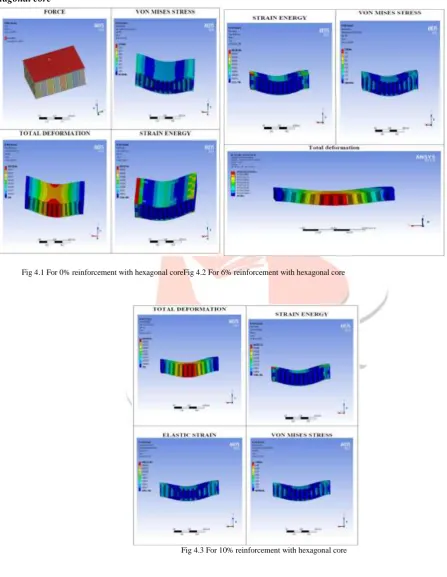
IV. STATIC ANALYSIS SIMULATION
Hexagonal core
Fig 4.1 For 0% reinforcement with hexagonal coreFig 4.2 For 6% reinforcement with hexagonal core
Fig 4.3 For 10% reinforcement with hexagonal core
IJEDR1602276
International Journal of Engineering Development and Research (www.ijedr.org)1546
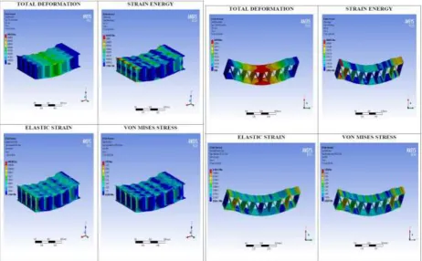
Fig 4.4 For 10% reinforcement with quad coreFig 4.5 For 10% reinforcement with truss core
I beam core
Fig 4.6 For 10% reinforcement with I-beam core
IJEDR1602276
International Journal of Engineering Development and Research (www.ijedr.org)1547
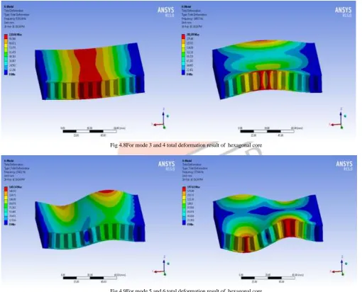
Fig 4.7 For mode 1 and 2 total deformation result of hexagonal core
Fig 4.8For mode 3 and 4 total deformation result of hexagonal core
IJEDR1602276
International Journal of Engineering Development and Research (www.ijedr.org)1548
V. RESULTS AND DISCUSSIONSSTATIC ANALYSIS
HEXAGONAL CORE
% 0F SI3N4
DEFORMATION mm
VON MISES STRESS MPa
ELASTIC STRAIN
STRAIN ENERGY(E)
0 0.0057506 13.796 0.00020825 0.0051972
6 0.0046639 15.867 0.00019007 0.0043021
10 0.0041905 15.908 0.00017132 0.0038783
Table 5.1
QUAD CORE
% 0F SI3N4
DEFORMATION mm
VON MISES STRESS MPa
ELASTIC STRAIN
STRAIN ENERGY(E)
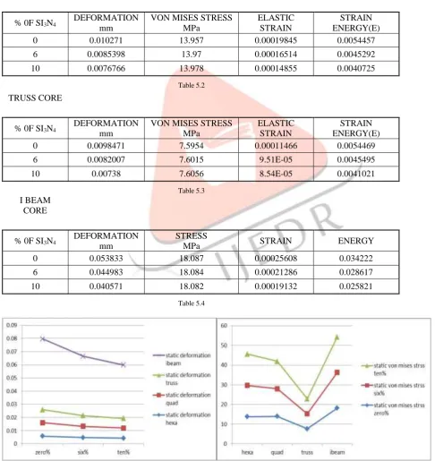
0 0.010271 13.957 0.00019845 0.0054457
6 0.0085398 13.97 0.00016514 0.0045292
10 0.0076766 13.978 0.00014855 0.0040725
Table 5.2
TRUSS CORE
% 0F SI3N4
DEFORMATION mm
VON MISES STRESS MPa
ELASTIC STRAIN
STRAIN ENERGY(E)
0 0.0098471 7.5954 0.00011466 0.0054469
6 0.0082007 7.6015 9.51E-05 0.0045495
10 0.00738 7.6056 8.54E-05 0.0041021
Table 5.3
I BEAM CORE
% 0F SI3N4
DEFORMATION mm
STRESS
MPa STRAIN ENERGY
0 0.053833 18.087 0.00025608 0.034222
6 0.044983 18.084 0.00021286 0.028617
10 0.040571 18.082 0.00019132 0.025821
Table 5.4
IJEDR1602276
International Journal of Engineering Development and Research (www.ijedr.org)1549
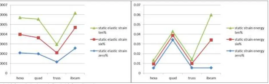
Graph 5.3 Overall elastic strainGraph 5.3 Overall strain energy
The overhead static analysis observation shows that deformation, strain energy, vonmises stress, and elastic strain is decreases in honeycomb structure with 10 % SI3N4 compare to other three different core. In truss core structure stress induced is less compare to honeycomb but deformation is more. Over all honey comb structure gives more stiffness compare to other three different core for static analysis.
MODAL ANALYSIS
FOR 10% WITH DIFFERENT MODELS
MODES HEXA QUAD TRUSS I BEAM
1 6534.3 6220.8 5773.9 2003.3
2 7986 7075.3 7084.7 3386.9
3 9191.4 9074.9 12033 4141.2
4 14017 12779 12382 6558.2
5 15412 13875 14153 6720.9
6 17364 14522 15236 9239.3
Table 5.5
Graph 5.4 Overall modal analysis
IJEDR1602276
International Journal of Engineering Development and Research (www.ijedr.org)1550
TRANSIENT ANALYSISHEXA
% 0F SI3N4 DEFORMATION VON MISES
STRESS
ELASTIC STRAIN
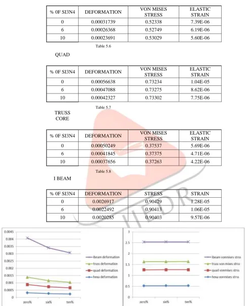
0 0.00031739 0.52338 7.39E-06
6 0.00026368 0.52749 6.19E-06
10 0.00023691 0.53029 5.60E-06
Table 5.6
QUAD
% 0F SI3N4 DEFORMATION VON MISES
STRESS
ELASTIC STRAIN
0 0.00056638 0.73234 1.04E-05
6 0.00047088 0.73275 8.62E-06
10 0.00042327 0.73302 7.75E-06
Table 5.7
TRUSS CORE
% 0F SI3N4 DEFORMATION VON MISES
STRESS
ELASTIC STRAIN
0 0.00050249 0.37537 5.69E-06
6 0.00041845 0.37375 4.71E-06
10 0.00037656 0.37263 4.22E-06
Table 5.8
I BEAM
% 0F SI3N4 DEFORMATION STRESS STRAIN
0 0.0026917 0.90429 1.28E-05
6 0.0022492 0.90413 1.06E-05
10 0.0020285 0.90403 9.57E-06
IJEDR1602276
International Journal of Engineering Development and Research (www.ijedr.org)1551
Graph 5.7 Overall dynamic elastic strain
The overhead transient analysis observation shows that deformation, strain energy, vonmises stress, and elastic strain is decreases in honeycomb structure with 10 % Si3N4 compare to other three different core. In truss core structure stress induced is
less compare to honeycomb but deformation is more VI. CONCLUSIONS AND FUTURE SCOPE
It is watched that ALUMINIUMhoneycomb sandwich board has more quality to weight proportion contrasted with uniform ALUMINIUM bar. From analysis test on the ALUMINIUM honeycomb sandwich beam example fluctuating the honeycomb center cell thickness, it was watched that with an expansion in the thickness of honeycomb center cell, the begin of plastic disfigurement could be deferred, bringing about increment of extreme quality. Twisting investigation is done on hexagonal honeycomb cored boards and there will be extension for study on square, TPS (level dividers or flat walls) and TPS (corrugated dividers) honeycomb cored boards. Distortion diminishes by presenting honeycomb structure. Stress and strains likewise diminishes by presenting honeycomb structure
VII. SCOPE FOR FUTURE EXPLORATION:
Stability of sandwich beam under various operating conditions such as thermal. Stability of sandwich beam under various boundary conditions.
Stability of multilayered sandwich beams
REFERENCES
[1]Amol A.Gokhale*, N.V. Ravi Kumar, B. Sudhakar, S. N. Sahu“Cellular Metals and Ceramics for Defence Applications Defence Science Journal”, Vol. 61, No. 6, November02011, pp. 567-575, DOI: 10.14429/dsj.61.640.
[2]ASTM C365-94 , “Standard Test Method for Flatwise Compressive Properties of Sandwich Cores”.
[3]A Chawla1 , S Mukherjee1,dDileep Kumar2, T. Nakatani3 and M. Ueno, “PREDICTION OF CRUSHING BEHAVIOUR OF HONEYCOMB STRUCTURES”.
[4]HONEYCOMB SANDWICH DESIGN TECHNOLOGY. Reference article.
[5]D.P.W. Horrigan and R.R Aitken, “Finite Element Analysis of Impact Damaged Honeycomb Sandwich” CS503 - Issue 1. [6]Daniel D. Nguyen1“Analysis and Testing of Heat Transfer through Honeycomb Panels” NASA TN D-944.
[7]FRANTIŠEK SIMANČÍK, Metallic foams – ultra light materials for structural Applications, INŹYNIERIA MATERIAŁOWA Nr.5/2001, 823-828.
[8]AligKurşun, Emre Kara, Recep Uygun, Halil Aykul , “Compressive behaviour of glass fiber reinforced Aluminium foam” , TOJSAT : The Online Journal of Science and Technology- January 2014, Volume 4, Issue 1. 9. Yong-Jai Kwon1, IchinorisShigematsu2 and Naobumi Saito , Development of New Production Technology for Metallic Foam Core Sandwich Panel Using Friction Phenomena, Materials Transactions, Vol. 50, No. 4 (2009) pp. 879 to 884, #2009 The Japan Institute of Metals.
[9]Jing Li, Zhong-Ping Zhang, Qiang Sun, Chun-Wang Li,“Mulitiaxial fatigue prediction for various metallic materials based on the critical plane approach” International Journal of fatigue, Vol.33, 2011, pp 90-101.
[10]Ali Fatemi, Nima Shamsaei “Multiaxial fatigue: An overview and some approximation models for life estimation” International Journal of fatigue, Vol.33, 2011, pp 948-958.
[11]Ellyin F, “Fatigue crack growth and life prediction”, London Champan and Hall,1997, pp 912-924
[12]Aleksandar Grbovic, Bosko Rasuo, “FEM based fatigue crack growth predictions for spar of light aircraft under variable amplitude loading”, Engineering Failure Analysis, Vol.26, 2012, pp 50-64.
[13]F. Walther, D Eifler, “Fatigue life calculation of SAE 1050 and SAE 1065 steel under random loading”, International Journal of Fatigue, Vol.29, 2007, pp 1885-1892.
[14]B. Li, L. Reis, M. de Freitas, “Simulation of Cyclic Stress/Strain Evolutions for Multiaxial Fatigue Life Prediction”, International Journal of Fatigue, Vol.28, 2006,a.451-458.