An Optimal approach for Placement of Distributed Generation Sources in Power Systems 1
S.Jayalakshmi, 2Dr. V. Balaji 1
Research Scholar, SCSVMV University, Kancheepuram 2
Associate Professor, Faculty of Electrical Engineering, Bahir Dar Institute of Technology,
Bahir Dar University,Bahir Dar, Ethiopia.
Abstract
Power system deregulation and the deficiency of transmission limits have prompted expanded enthusiasm for distributed generation (DG) sources which is a promising answer for some force system issues, for example, voltage regulation, power loss, and so forth. The area in the force system for DG position is observed to be imperative. Designation of conveyed era at non-ideal spots prompts expanded power loss and lessened bus voltage profiles. By legitimate situation of DG at ideal bus area the monetary expense and dynamic power loss can be minimized then the relating bus voltages will be moved forward. This paper presents expository techniques to decide the ideal area to put a DG in outspread organized systems to minimize the power loss of the system. Recreation results are given to check the proposed investigative methodologies
Key words —Analytical methodology,
distributed generation, operational placement, power loss.
INTRODUCTION
The ever expanding requirement for electrical force generation, enduring advancement in the force deregulation and utility rebuilding, and tight limitations over the development of new transmission lines for long separation power transmission have made expanded enthusiasm for dispersed force era. Distributed era (DG) gadgets can be deliberately put in force systems
for matrix support, decreasing force
misfortunes and on-top working costs, enhancing voltage profiles and load considers, conceding or disposing of for system updates,
and enhancing system uprightness, unwavering quality, and effectiveness [1]–[5].
These DG sources are ordinarily set near utilization focuses and are included for the most part at the dissemination level. They are generally little in size (with respect to the force limit of the system in which they are put) and particular in structure. A typical methodology to discover the site of DG is to minimize the force loss of the system [2]–[5]. Another technique for putting DG is to apply decides that are regularly utilized as a part of sitting shunt capacitors in appropriation systems. A "2/3 tenet" is exhibited in [6] to place DG on an outspread feeder with consistently conveyed load, where it is recommended to introduce DG of roughly 2/3 limit of the approaching era at around 2/3 of the length of line. This principle is basic and simple to utilize, however it can't be connected specifically to a feeder with different sorts of burden conveyance, or to an arranged system. References [1] and [7] present force stream calculations to locate the ideal size of DG at every heap bus in an organized system accepting that each heap bus can have a DG source.
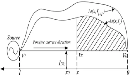
Fig. 1. A feeder with circulated loads along the line.
position of DG in an outspread feeder is broke down and the theoretical ideal site (bus) for including DG is gotten for various sorts of burdens and DG sources. At that point, a strategy is introduced to locate the ideal bus for putting DG in an arranged system in light of bus induction network, era data and burden distribution of the system. The proposed strategies are tried by a series of reproductions on spiral feeders, an IEEE 6-bus test system [1], an IEEE 30-bus test system [11], and a subset of it, to demonstrate the adequacy of the proposed techniques in deciding the ideal bus for setting DG.
By and by, there are more limitations on the accessibility of DG sources, and we might just have one or a couple of DGs with limited yield accessible to include. Thusly, in this study the DG size is not thought to be upgraded. The strategy to decide the ideal bus for putting DG might likewise need to take into air conditioning check different elements, for example, monetary and geographic considerations. These variables are not examined in this paper.
II. OPTIMAL PLACEMENT OF DG ON A RADIAL FEEDER
To disentangle the investigation, just overhead transmission lines with consistently conveyed parameters are considered,
i.e., R and L per unit length are the same along the feeder while C and G per unit length are disregarded. The heaps along the feeder are
assumed to shift in discrete time length of time;
The objective is to add DG in an area to
minimize the aggregate normal force
misfortune and guarantee that the voltages along the feeder are in the satisfactory extent, 1 to 0.05 p.u..
The solution x0 of the above mathematical statement will give the ideal site for minimizing the power loss, however it can't promise that every one of the voltages along the feeder are in the satisfactory extent. On the off chance that the voltage regulation can't be fulfilled in the meantime, the DG can be put around x0 to fulfill the voltage regulation standard while diminishing the power loss however much as could reasonably be expected, or the DG size can be expanded. The explanatory technique to decide the ideal point to place DG on an outspread feeder is given as takes after.
TABLE I
THEORETICAL ANALYSIS RESULTS OF CASE STUDIES WITH TIME INVARIANT LOADS AND DGS
Table I demonstrates the aftereffects of examinations, utilizing the prior technique, to locate the ideal area for putting DG on radial feeders with three diverse burden circulations:
consistently dispersed burden, midway
conveyed load. In the outcomes given in Table I, it is expected that the DG supplies every one of the heaps on the feeder for every situation, and the conveyance system supplies the system losses.
It is noted from this table the DG lessens the system power misfortunes fundamentally when it is found legitimately. The 2/3 guideline exhibited in [6] functions admirably when the heap is consistently conveyed along the feeder, yet it gives off base results if the heap setup is distinctive. For a consistently distributed load, if the DG supplies 2/3 of the aggregate burden.
III. OPTIMAL PLACEMENT OF DG IN
NETWORKED SYSTEMS
The hypothetical examination for putting a DG in arranged sys-tems is distinctive and more confused than in a spiral feeder. To improve the examination, one and only DG is thought to be added to the system.
Fig-2 A networked power system.
Consider the system appeared in Fig. 2 with a DG added to the system to strengthen it. The system has N buss and stacks, and the DG is situated at a bus, say bus . The primary outer force is infused into bus 1, which is taken as slack bus. The goal is to discover the bus to introduce the DG so that the aggregate system power misfortune is minimized and the voltage level at every bus is held in the worthy reach, 1 0.05 p.u. Prior to the DG is added to the system, the bus remittance matrix is
where 0 superscript signifies the first system. Expecting that the DG is situated at system , the system concede tance lattice is changed from to by considering that system 1 and system are associated together. Really there is no line to associate those buses together, however the nonexistent line will help in finding the ideal area to include DG. is one measurement not exactly with the exception of when the DG is situated at system 1. In the event that the DG is at system 1, network will be the same as . To get the new grid when the DG source is associated, we treat the new system impedance matrix Zbus is as
IV. Recreation RESULTS
A few recreation studies were completed to confirm the outcomes acquired diagnostically for both outspread and system associated systems.
A. Spiral Feeder With Time Invariant Loads and DG
A spiral feeder with a period invariant DG was recreated under consistently conveyed, midway appropriated and progressively disseminated loads. The reproduced system for consistently dis-tributed burdens is appeared in Fig. 3. The system design is the same when the heaps are halfway circulated or progressively dispersed.
In Table II, the ideal system for setting DG to
minimize the aggregate system power
misfortune is given for every heap
concur well with hypothetical qualities. While a few system voltages fall far out of the satisfactory reach when there is no DG in the system, every one of the system voltages are inside of 1 0.05 p.u. with the DG included.
Table-2, SIMULATION RESULTS OF CASE STUDIES WITH TIME INVARIANT LOADS AND DG
Fig. 3. Annual daily average output power profile of a 1-MW wind-DG.
Fig. 4. Daily average demand of a typical house.
Fig. 5. Power losses of the system in Fig. 7 with a 5-MW DG.
Fig. 6. Power losses of the radial feeder with the wind-DG at different buses.
Networked Systems
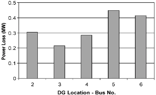
The 25-kV IEEE 6-system system appeared in Fig. 7 [1], which can be considered as a sub transmission/dispersion system, was connected to confirm the strategy displayed in Section III. The dad rameters of this system are given in Appendix B. A 5-MW DG was added to fortify the system. Absolute system power misfortune was gotten from the aftereffects of influence stream thinks about when DG was set at various systems (Fig. 7). It is noted from this assume least power misfortune is accomplished when DG is set at system 3. The estimations of the target capacity for the system were ob-tained
methodology when the DG was set at various systems. These qualities are appeared in the bar diagram of Fig. 9. It is noted from this assume the target capacity is additionally at its base when the DG is put at system 3, demonstrating that the outcome acquired from the proposed systematic technique is the same as the reenactment result.
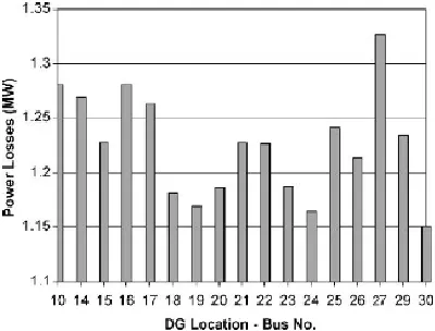
The proposed strategy was likewise tried on the IEEE 30-system test system appeared in Fig. 10, which can be considered as a coincided transmission/ sub transmission system [11]. The system has 30 systems (principally 132-and 33-kV systems) and 41 lines. The system system information is given in Appendix C. A 15-MW DG (around 5% of the aggregate system heap of ) is thought to be added to fortify the system. The aggregate force loss of the system achieves a base quality when DG is situated at system 5, as appeared in Fig. 8. The ideal system controlled by the technique proposed in this paper is likewise system 5, as given in Fig. 9.
A DG source may not be associated straightforwardly to a 132-kV (system 5 in Fig. 8) as controlled by the proposed technique. Thus, a subset of the 30-system test system with lower voltage
Fig. 7. Power losses of the IEEE 30-bus test system with a 15-MW DG.
Fig. 8. Values of the objective function of the IEEE 30-bus system.
Fig. 9. Power losses of the subset system in Fig. 10 with a 5-MW DG.
level (33 kV), as demonstrated in Fig. 8, was likewise tried the proposed technique. The new system has 18 systems, 22 lines, and an aggregate heap of . A 5-MW DG (about 5% of the aggregate heap of the subset) was added to the system. Recreation results for this system are given in Fig. 9. It is noticed that the aggregate system misfortune achieves a base worth when the DG is situated at system 30. The ideal spot recommended by the proposed technique is likewise system 30, as appeared in Fig. 14.
Conclusion
minimize power misfortunes. The proposed methodologies are not iterative calculations, similar to power stream programs. Along these lines, there is no merging issues included, and results could be acquired rapidly. A progression of reproduction studies have been led to check the legitimacy of the proposed approaches, and comes about demonstrate that the proposed
techniques function admirably. The
consequences of this paper have demonstrated that Distributed Generation (DG) is a promising answer for some force system issues, for example, voltage regulation, power misfortune, and so on. The area in the force system for DG position is observed to be vital. Designation of circulated era at non-ideal spots prompts expanded force misfortune and lessened system voltage profiles.
References
[1] N. S. Rau and Y.-H. Wan, “Optimum location of resources in distributed planning,” IEEE Trans. Power Syst., vol. 9, pp. 2014–2020, Nov. 1994.
[2] K.-H. Kim, Y.-J. Lee, S.-B. Rhee, S.-K. Lee, and S.-K. You, “Dispersed generator placement using fuzzy-GA in distribution systems,” in Proc. 2002 IEEE Power Engineering Soc. Summer Meeting, vol. 3, Chicago, IL, July 2002, pp. 1148–1153.
[3] N. Hadjsaid, J. F. Canard, and F. Dumas, “Dispersed generation im- pact on distribution networks,” IEEE Comput. Appl. Power, vol. 12, pp. 22–28, Apr. 1999.
[4] T. Griffin, K. Tomsovic, D. Secrest, and A. Law, “Placement of dispersed generation systems for reduced losses,” in Proc. 33rd Annu. Hawaii Int. Conf. Systems Sciences, Maui, HI, 2000.
[5] M. H. Nehrir, C. Wang, and V. Gerez, “Impact of wind power distributed generation on distribution systems,” in Proc. 17th Int. Conf. Electricity Distribution (CIRED), Barcelona, Spain, May 2003.
[6] H. L. Willis, “Analytical methods and rules of
thumb for modeling DG-distribution
interaction,” in Proc. 2000 IEEE Power Engineering Society Summer Meeting, vol. 3, Seattle, WA, July 2000, pp. 1643–1644.
[7] J. O. Kim, S. W. Nam, S. K. Park, and C. Singh, “Dispersed generation planning using improved hereford ranch algorithm,” Elect. Power Syst. Res. , vol. 47, no. 1, pp. 47–55, Oct. 1998.
[8] W. Kellogg, M. H. Nehrir, G. Venkataramanan, and V. Gerez, “Genera- tion unit sizing and cost analysis for stand-alone wind, photovoltaic, and hybrid wind/PV systems,” IEEE Trans. Energy Conversion, vol. 13, pp. 70–75, Mar. 1998.
[9] J. Cahill, K. Ritland, and W. Kelly, “Description of Electric Energy Use in Single Family Residences in the Pacific Northwest,” Office of Energy Resources, Bonneville Power Administration, Portland, OR, Dec. 1986–1992.
[10] J. Duncan Glover and M. S. Sarma, Power System Analysis and Design, 3rd ed. Pacific Grove, CA: Brooks/Cole, Thomson Learning, Inc., 2001.