IJEDR1601110
International Journal of Engineering Development and Research (www.ijedr.org)643
Effect of Welding parameters on bead geometry of
weld by GMAW Process
1Rakesh Ranjan, 2Ajit Kumar, 3Avinaw Pratik 1Student, 2Student
1Department of Foundry and Forge Technology, 1NIFFT Ranchi, India
________________________________________________________________________________________________________ Abstract- The objective of the present work is an attempt to study the effect of various welding parameters on bead geometry of mild steel specimen having 5.5mm thickness welded by Gas Metal Arc welding process. The welding current, arc voltage and welding speed were chosen as variable parameters. Tests were conducted using CO2 as shielding gas (MAG welding) and shielding gas (MIG welding). The bead height and depth of penetration were measured for each specimen after the welding operation. Further the ultimate tensile strength, Vickers hardness test, flaw detection and grain structure study was conducted and the effect of the variable parameters were studied.
Keywords:- welding current, arc voltage ,welding speed, bead height, depth of penetration
________________________________________________________________________________________________________
I. INTRODUCTION
Gas metal arc welding (GMAW) process is an important component in many industrial operations. The research on controlling GMAW metal transfer modes is essential to high quality welding procedures. The GMA welding parameters are the most important factors affecting the quality, productivity and cost of welding joint. Weld bead size and shape are important considerations for design and manufacturing engineers in the fabrication industry. In fact, weld geometry directly affects the complexity of weld schedules and thereby the construction and manufacturing costs of steel structures and mechanical devices. [1] Above all, welding current intensity has the strongest effect on melting capacity; weld bead size, geometry and depth of penetration. It must be well determined in thin parts, because excessive amounts of welding current and a large welding bath cause high penetration depths. In contrast to this, very low welding current causes inadequate penetration thus accumulating welding metal on base metal. When all parameters are held constant, weld bead area expands with increasing voltage. Relatively low welding speeds cause accumulation of welding metal, large welding bath and thus low penetration. The deepest penetration values are obtained in optimum values of welding speed. [2]
P.K. Palani et.al. (2006) presented the importance to select a proper combination of parameters of the pulsed current for welding, which will ensure that the process gives proper results in all aspects. However, arriving at such a combination of parameters without a rational base would be only a matter of chance with a fairly low probability for achieving desirable weld properties, since the complexity and interdependence of pulse parameters involved in this process. These difficulties of setting-up the welding conditions correctly has been one of the main reasons for the lack of popularity of pulsed GMA welding in industries. Hence, a detailed study is essential to arrive at a method of predicting the conditions that will give a good weld and this paper reviews various aspects of the pulsed GMA welding, the effects of pulse parameters and different methodologies adopted for selecting these parameters to obtain better quality welds. [3]
S. P. Tewari et.al. (2010) presented the effect of various welding parameters on the weldability of Mild Steel specimens having dimensions 50mm× 40mm× 6 mm welded by metal arc welding were investigated. The welding current, arc voltage, welding speed, heat input rate are chosen as welding parameters. The depth of penetrations were measured for each specimen after the welding operation on closed butt joint and the effects of welding speed and heat input rate parameters on depth of penetration were investigated.. [4]
Ahmed Khalid Hussain et. al. (2010) investigated the effect of welding speed on the tensile strength of the welded joint. Experiments were conducted on specimens of single v butt joint having different bevel angle and bevel heights. The material selected for preparing the test specimen is AluminiumAA6351 Alloy. The strength of the welded joint is tested by a universal tensile testing machine and the results were evaluated.. [5]
II. RESEARCHOBJECTIVE
The objective of the present work is:-
‒ Study the effect of various welding parameters on bead geometry of mild steel specimen by Gas Metal Arc welding process.
‒ The welding current, arc voltage and welding speed were chosen as variable parameters.
‒ Tests were conducted using CO2 as shielding gas (MAG welding) and shielding gas (MIG welding). ‒ The bead height and depth of penetration were measured for each specimen after the welding operation.
IJEDR1601110
International Journal of Engineering Development and Research (www.ijedr.org)644
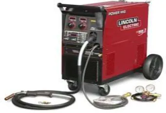
Fig 1. The welding machine used for the experimentEighteen mild steel with dimensions 110x40x5.5mm was used during the experiment. The chemical composition of the mild steel is as follows:
Table 1. Chemical Composition of Mild Steel
CARBON SILICON MANGANESE SULPHUR PHOSPHORUS
0.35-0.45% 0.05-0.35% 0.60-1% < 0.06% < 0.06%
The presence of different elements and their effect upon the property of the Mild Steel is: 1) Carbon: It increases strength & hardness in the weld.
2) Silicon: A non-metallic material often added to GMAW electrodes to act as a deoxidizer.
3) Manganese: A hard, brittle, gray-white metal often added to GMAW electrodes. Manganese acts as a deoxidizer and increases strength and hardness in the weld.
4) Sulphur: It increases the machinability of the weld but lowers transverse ductility.
5) Phosphorous: It increases strength & hardness at the expense of ductility and impact to toughness of the weld.
a. The MIG/MAG welding apparatus used during the experiment was of model MAXIMIN 251.It has the range of 250 amperes with a supply voltage 415 V & the maximum input current of 14 Ampere.
b. The diameter of the mild steel feed wire used in MIG/MAG welding was 0.8 mm.
c. The shielding gas used during MAG was CO2 while that used in MIG welding was ARGON. Carbon dioxide: An active gas commonly used as shielding for GMAW. Carbon dioxide is inexpensive but yields a violent arc.
Argon: An inactive gas commonly used as shielding. Argon is much heavier than air, so it effectively shields the weld area.
d. The total number samples used were eighteen in number. The V- shaped edge preparation of all the samples were done with the help of bastard file.
e. Subsequent to edge preparation, the specimens were tacked. Tacking was done for the proper alignment of the samples. f. The MAG/MIG welding was done in the horizontal direction. The torch angle was 20-30⁰ with horizontal.
g. The variable parameter chosen were welding current, voltage & welding speed .welding current and voltage were chosen as parameter because the extent to which the parent material melt depends on the heat generated during welding. Higher the current and voltage, higher will be the heat generated and vice-versa. Optimum welding speed was maintained in order to get the desired penetration.
h. The strength of the joint obtained after MAG welding were not very strong.
i. The process was followed by MIG welding and the strength of joint was found to be satisfactory.
IJEDR1601110
International Journal of Engineering Development and Research (www.ijedr.org)645
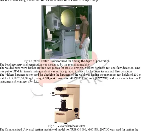
Fig 2. Chop saw used for cutting the welded componentk. The bead height and depth of penetration was studied with the help of optical profile projector, which gave the bead height. The optical profile projector of model METZ-801A (vertical floor type) was used for measuring the bead penetration. The machine is having Projection screen of rotatable fine grain ground with cross hair line detachable clips, Work stage of 200mm X 200mm with 0-25mm micrometer adjustment with least count 0.1mm, Contour illuminator of 24V-150/250W halogen lamp and surface illuminator of 12V-100W halogen lamp.
Fig.3. Optical Profile Projector used for finding the depth of penetration l. The bead geometry and penetration was measured by the scanning machine.
m. The welded parts were further cut into two pieces for tensile strength, Vickers hardness test and flaw detection. One set was put to UTM for tensile testing and set was surface grinded to check for hardness testing and flaw detection.
n. The Vickers hardness tester used for checking the hardness of the weld was having the maximum test height of 230 mm, test load 5,10,20,30,50 kgf , weight 70kgs & dimension 460X225X860 mm (LXWXH) and its manufacturer is Fuel instruments & engineers Pvt Ltd.
Fig 4. Vickers hardness tester
IJEDR1601110
International Journal of Engineering Development and Research (www.ijedr.org)646
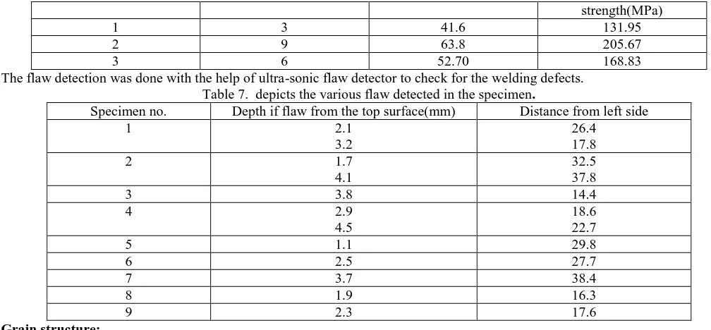
Fig 5. Ultimate Tensile Strength Testing Machinep. The flaw detection machine of model Ultrasonic 4400MV was used for detecting the flaw in the weld. The machine is having the frequency range of 0.5-12 MHz (25MHz optional), Gain 103db Adjustable in 0.25/0.5/0.75/1/2 / 6/20db Steps, sensitivity 140db±3db, suppression adjustable from 50% height of CRT Screen scale & testing range of 0-10mm to 0-10 mts. in steel in 5 convenient steps.
Fig 6. Ultrasonic flaw detector
q. The grinded specimens were further cut into small pieces. These small pieces were then moulded in the fixture with the help of Rapid repair self polymerizing resin for all acrylic denture repair. The cross section was polished using the water paper of grade 120, 320, 600, 800, 1200 & 2000 to study for the grain structure. The polished surface was then etched with diamond paste. Buffering with velvet cloth was also done simultaneously and the mould was prepared for holding the small specimens which were to be further polished.
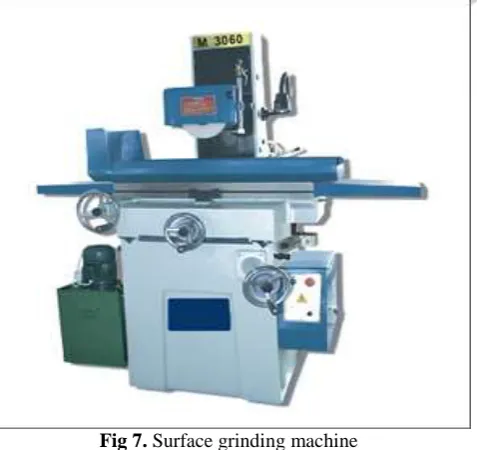
r. Surface Grinding machine:-The surface grinding machine used for grinding the welded surface is having the dimension of the working table 225X450mm, maximum height from table to grinding wheel 275mm, vertical feed least count 0.01mm, micro feed least count 0.002mm & cross feed least count 0.05mm. The machine is having maximum spindle speed of 2800 rpm and the diameter of the grinding wheel is 200mm.
Fig 7. Surface grinding machine
IJEDR1601110
International Journal of Engineering Development and Research (www.ijedr.org)647
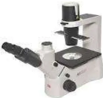
Fig. 8. Inverted microscopeIV. RESULTANDDISCUSSION
Table 2 deals with the results obtained during the welding process of Mild Steel specimen (110X50X5.5mm) using CO2 as the shielding gas. Carbon dioxide (CO2 ), a reactive gas, dissociates into carbon monoxide and free oxygen in the heat of the arc. Oxygen then combines with elements transferring across the arc to form oxides from the weld pool in the form of slag and scale, generating a great deal of smoke and fumes. Thus, the joints produced by MAG welding did not have much strength. Carbon dioxide does not support spray transfer. Metal transfer is restricted to the short circuiting and globular modes. A major disadvantage of carbon dioxide is harsh globular transfer with its characteristic spatter. Hence, in order to have a joint with high strength MIG welding was done subsequently to MAG welding.
Table 2. Values of Welding Parameter Obtained during MAG Sl.
No.
Wire Feed Rate(m/min)
Welding Current(A)
Welding Voltage(V)
Fine Coarse Welding Speed (mm/sec)
1. 9 95 18 4 3 2.02
2 9 95 20 3 4 2.29
3 9 95 22 4 4 2.26
4 11 105 18 4 3 2.29
5 11 105 20 3 4 2.68
6 11 105 22 4 4 2.75
7 14 115 18 4 3 2.50
8 14 115 20 3 4 2.75
9. 14 115 22 4 4 2.24
Table 3 deals with the results obtained during the welding process of Mild steel specimen (110X50X5.5mm) using argon as the shielding gas. Argon provides excellent arc welding stability, penetration, and bead profile, when welding ferrous-based metals. The low ionization potential of argon helps create an excellent current path and superior arc stability. Argon produces a constricted arc column with high current density which causes the arc energy to be concentrated over a small surface area. Hence the joint produced by argon was found to be stronger than that produced by MAG welding which used CO2 as the shielding gas.
Table 3. Values of Welding Parameter Obtained during MIG Sl. No. Wire Feed
Rate
Welding Current
Welding Voltage
Fine Coarse Welding
Speed (mm/sec)
Bead penetration in mm
1. 7 95 18 4 3 2.33 8.73
2 7 95 20 4 4 2.20 8.95
3 7 95 22 4 4 2.27 9.22
4 8 105 18 4 3 2.00 9.32
5 8 105 20 4 4 2.20 9.38
6 8 105 22 3 4 2.01 9.53
7 9 115 18 4 3 2.55 9.41
8 9 115 20 3 4 2.24 9.86
IJEDR1601110
International Journal of Engineering Development and Research (www.ijedr.org)648
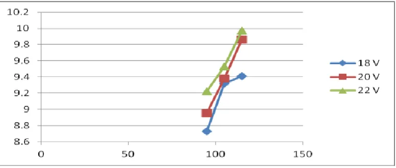
Fig 9. Plot of Current(X axis) Vs Penetration(Y axis) with constant VoltageIt is quite evident from the graph that as the voltage is increasing the depth of penetration also increases linearly and vice –versa. The maximum bead penetration of 9.97mm was found at 22Vand115A.
Fig 10. Plot of Voltage(X axis) Vs Penetration(Y axis) with constant current
From the graph it can be concluded that depth of penetration and voltage are directly proportional to each other. As the welding current increases the bead penetration also increases and vice –versa. The maximum penetration was found at 22V.
The welded specimen was studied in optical profile projector. Then the specimen were scanned in the scanner. The value of bead height obtained are presented in the table
Table 4. Values of bead height
Sl. No. Lower
Dimension(L)
Middle Dimension(M)
Upper Dimension(U)
Bead height (U-L)(mm)
1. 6.51 11.21 15.24 8.73
2. 2.09 8.01 11.04 8.95
3. 2.09 7.37 11.31 9.22
4. 3.03 8.43 12.35 9.32
5. 6.01 12.4 16.46 9.38
6. 5.83 11.22 15.36 9.53
7. 1.11 6.77 10.13 9.41
8. 1.36 6.95 11.23 9.86
9. 0.94 6.24 9.81 9.97
The scanned images of the specimens from the scanner showing the bead height and depth of penetration are given below.
IJEDR1601110
International Journal of Engineering Development and Research (www.ijedr.org)649
. (d) (e) (f)
(g) (h) (i)
Fig.11. Scanned images of the specimens from the scanner showing the bead geometry formed with different current, voltage and welding speed. The bead height and depth of penetration values (P) is presented in each case.
Fig. (a) Welding current=95A, arc voltage=18V, welding speed=2.33 mm/sec, P=8.73mm Fig. (b) Welding current=95A, arc voltage=20V, welding speed=2.20mm/sec, P=8.95mm. Fig. (c) Welding current=95A, arc voltage=22V, welding speed=2.27mm/sec, P= 9.22mm. Fig. (d) Welding current=105A, arc voltage= 18V, welding speed =2.00mm/sec, P=9.32mm. Fig. (e) Welding current=105A, arc voltage=20V, welding speed =2.20mm/sec, P= 9.38mm. Fig. (f) Welding current=105A, arc voltage =22V, welding speed= 2.01mm/sec, P=9.53mm. Fig. (g) Welding current of 115A, arc voltage 18V, welding speed=2.55mm/sec, P= 9.41mm. Fig. (h) Welding current=115A, arc voltage=20V, welding speed =2.24mm/sec, P= 9.86mm. Fig. (i) Welding current =115A, arc voltage =22V, welding speed=2.26mm/sec, P=9.97mm. In order to measure the hardness of the welded joint Vickers hardness tester was used.
Vickers HB=1.854F/d2
Where F= load in Kgf & d=Diameter of diagonal of the indentation.
Table 5. Represents the data recorded for hardness tested in the Vickers hardness testing machine. Specimen no. Observation 1
(in mm)
Observation2 mean Table value Calculated value
1 d1 = 0.425 d2=0.459
d1=0.472 d2=0.445
0.4500 275 274.60
2 d1=0.470 d2=0.471
d1=0.476 d2=0.451
0.4670 255 255.03
3 d1=0.461 d2=0.460
d1=0.457 d2=0.460
0.4595 264 263.40
4 d1=0.463 d2=0.459
d1=0.471 d2=0.467
0.465 256 255.8
5 d1=0.488 d2=0.478
d1=0.499 d2=0.500
0.4910 231 230.70
6 d1=0.469 d2=0.463
d1=0.479 d2=0.465
0.4685 254 253.40
7 d1=0.462 d2=0.454
d1=0.462 d2=0.468
0.4615 262 263.40
8 d1=0.450 d2=0.462
d1=0.486 d2=0.481
0.4697 253 252.10
9 d1=0.491 d2=0.482
d1=0.474 d2=0.460
0.4760 246 245.48
Hence the welded joint of specimen 1 which had the lowest welding configuration wad found to be hardest and the welded joint of specimen 5 was found to be least hard. Thus for a given current the specimen with least arc voltage was found to have maximum hardness and the one with maximum arc voltage was found to have least hardness.
The values of ultimate tensile strength and peak load for three welding configurations having low current, medium current and high current with high voltage is presented in Table 6.To keep the number of experiments minimum, the ones with highest welding configurations were selected keeping in view that the lower ones would definitely fail below the values obtained.
Table 6. Represents the value of ultimate tensile strength
IJEDR1601110
International Journal of Engineering Development and Research (www.ijedr.org)650
3.2 17.8
2 1.7
4.1
32.5 37.8
3 3.8 14.4
4 2.9
4.5
18.6 22.7
5 1.1 29.8
6 2.5 27.7
7 3.7 38.4
8 1.9 16.3
9 2.3 17.6
Grain structure:
The grain structure of the polished mild steel specimen was studied in the inverted microscope to study the microstructure. The results are described below-:
Fig.12: Microstructure of Mild Steel (~0.16 wt% C) showing light-coloured ferrite grains and dark-appearing pearlite regions (Magnification: 500X; Volume fraction of pearlite is estimated to be around 20%)
Fig.13: Microstructure of mild steel with lower carbon content (~0.07 wt% C) showing light-coloured ferrite grains and dark-appearing pearlite regions (Magnification: 500X; Volume fraction of pearlite is estimated to be around 9%)
V. CONCLUSIONS
In the present work the Gas Metal Arc Welding was done to check the strength of the welded joints. The GMAW welding process is a welding process which yields fusion of metals by heating with a welding arc between a continuous filler metal electrode and the work piece. The continuous wire electrode which is drawn from a reel by an automatic wire feeder and then fed through the contact tip inside the welding torch is melted by an internal resistive power and heat transferred from welding arc. The objective of the present work is an attempt to study the effect of various welding parameters on bead geometry of mild steel specimen having 5.5mm thickness welded by Gas Metal Arc welding process. The welding current, arc voltage and welding speed were chosen as variable parameters.
IJEDR1601110
International Journal of Engineering Development and Research (www.ijedr.org)651
‒ In addition to welding current, the depth of penetration also increases with increase in arc voltage.‒ The maximum value of tensile strength and peak load was found to be 205.67 MPa and 63.8 KN respectively, obtained under medium current and high voltage condition. The welded joints have been found to fracture from the weld deposit, close to fusion line. This is because of presence of porosity in this area.
‒ It was observed that for a given current the specimen with least arc voltage was found to have maximum hardness and the one with maximum arc voltage was found to have least hardness.
‒ More flaws were detected in the specimens that were welded at low current and low voltage.
‒ The optimum welding configuration was found as 105A welding current, 18V arc voltage and 2.00 mm/s weld speed.
VI. REFERENCES
[1]. K.N. Braszczy, nska-Malika, M. Mróz” Gas-tungsten arc welding of AZ91 magnesium alloy” Journal of Alloys and Compoundsc(2011).
[2]. Erdal Karadeniz, Ugur Ozsarac, Ceyhan Yildiz “The effect of process parameters on penetration in gas metal arc welding processes” Materials and Design 28 (2007) 649–656.
[3].P.K. Palani ,N. Murugan “Selection of parameters of pulsed current gas metal arc welding”. Journal of Materials Processing Technology 172 (2006) 1–10.
[4]. S. P. Tewari , Ankur Gupta,Jyoti Prakash “Effect of welding parameters on weldability of material” International Journal of Engineering Science and Technology Vol. 2(4), 2010, 512-516