3227
A Numerical Approach To Cutting Tool Stress In
Cnc Turning Of En8 Steel With Silicon Carbide
Tool Insert
Dr.S. Ganeshkumar Dr.R. Sureshkumar. Y. Sureshbabu, S.Balasubramani
Abstract: This article reveals the stress behaviour of turning tool insert by finite element approach while machining of EN8 cylindrical workpiece. The numerical approach is described for stress behaviour by using stiffness matrices. The stress analysis is performed using ANSYS FEA software, and the results are compared with mathematical equations using finite element method. The part modelling of tool holder and tool insert is don e in PTC CREO ELEMENTS modelling software, and it is exported to the ANSYS FEA software in IGES format. Also, we are demonstrating the deflection behaviour of tool insert and tool holder, while machining of the EN8 cylindrical workpiece. The results obtained from the stiffness matrices and finite element approach by ANSYS software depicts similarity of stress acting on the tool inserts while machining.Moreover, this article validates the conventional finite element equation results.
Keywords: Stiffness matrices, ANSYS FEA, EN8 steel, Governing equation, deflection 1.Stress analysis of tool insert:
————————————————————
INTRODUTION
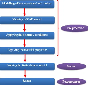
The methodology adopted in finite element analysis is shown in figure 1.1. The Tool insert and tool holder are modelled in PTC CREO ELEMENTS modelling software, and it is exported to the ANSYS FEA software. The part model imported from PTC CREO ELEMENTS to ANSYS is shown in figure 1.2 In this software, CAD model is converted to finite element model and the boundary conditions are given to the finite element model in pre-processor module.
Figure 1.1 – Methodology adopted in Finite Element approach
The cutting forces observed in the lathe tool dynamometer is given as the boundary conditions in ANSYS FEA software. In addition, at one end of the beam, all the degrees of freedom are arrested. (tool holder and insert assembly is assumed as cantilever beam). The stress contour plot obtained in post processor is depicted in figure 5.3.
Figure 1.2 Tool holder and the tool insert in ANSYS FEA software
Figure 1.3 Stress distribution in tool insert obtained in ANSYS software
2.Mathematical calculation of stress acting on
the tool insert:
The following assumptions are made to determine the stress acting on uncoated Silicon Carbide tool insert,
(i) The tool insert is considered as a cantilever beam
and the cutting force is given as a point load.
(ii) One-dimensional approach is followed.
(iii) The finite element model of cantilever beam is divided into 10 nodes 9 elements.
In general, the force due to self-weight (for tool insert and tool holder assembly) is given by
__________________________________
Dr.S. Ganeshkumar Assistant Professor-Sri Eshwar College of Engineering-Coimbatore
Dr.R. Sureshkumar Professor – Sri Eshwar College of Engineering – Coimbatore
Mr.Y. Sureshbabu Assistant Professor – Sri Eshwar College of Engineering – Coimbatore
3228
Where - ρ - Density of the material – Kg/mm3
A-
Area of cross section – mm2l- Length of the element – mm
Among the 9 elements, two types of materials are assigned; there are tool insert and tool holder. One end of the beam is fixed. (tool insert and tool holder assembly are assumed as a cantilever beam). Hence, the displacement of fixed node is zero. The cutting force is given on free end of the cantilever beam. The diagrammatic representation of tool holder and tool insert (cantilever beam) is shown in the figure 2.1.
Figure:2.1 – Schematic representation of tool holder and tool insert (Cantilever beam)
The stress acting on uncoated Silicon Carbide tool insert using the finite element method is solved mathematically as follows.
Where,
σ - Stress acting on the element – N/mm2
E - Young‘s Modulus of material – N/mm2
Δu – Change in deformation of beam – mm
3.. Determination of the force acting on each
nodes:
In general, the finite element equation for the one dimensional two node bar element is given by equation
Similarly, for the ten nodes, F3, F4…. F10 – is calculated and
the matrix is given by
In above equation. F1 is neglected, since the displacement of
the node 1 is zero. Then the reduced 9 x 1 matrix is By
substituting the load (due to the self-weight) for tool holder and tool insert, the force matrix is determined as shown in above Equation. In this equation, P1 and P2 are the material
properties of the tool holder and tool insert respectively. The material property of the tool holder elements is similar to each other. Hence, for all nodes of the tool holder, force (due to the self-weight) is given by P1. The force (due to self-weight)
acting on the tool insert is given by P2.
Where P1 and P2 are the Load acting on the nodes due to
self-weight of tool holder and tool insert respectively.
4.Determination of the stiffness matrix [K]:
In general, for a single element, the stiffness matrix [K] is given by
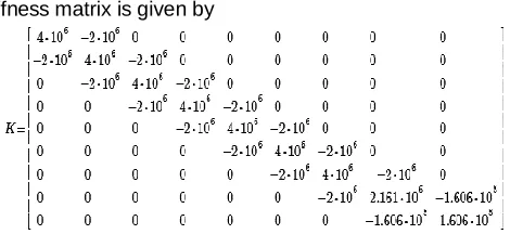
The stiffness matrix is determined for ten nodes, then the equation is modified for ten nodes then the stiffness matrix is illustrated in following equation. The material properties are substituted in this equation. Where, M1 to M8 are the material
property of the tool holder and Mi is the material property of
the tool insert. These M1 to M8 and Mi values are substituted in
3229
By substituting the values of M1 to M8 and Mi values, the
stiffness matrix is given by
5.Determination of the displacement matrix:
In general, the displacement matrix for the finite element equation is given by, [F]=[k] . [U], Where [U] is the displacement matrix. In the above equation, [U] matrix is determined using the crammer‘s rule as shown in following equation
In equation, ‗N‘ is assumed as force matrix. The displacement of all nodes is calculated using above equation by Crammer‘s rule. This displacement values are ulitlised to determine the stress acting on the tool insert. The inverse of stiffness matrix is determined as follows.
6.Determination of the inverse stiffness matrix:
The cutting force is added in the equation at the 10th node, then [N] matrix is given by
displacement at nodes:
U1= 0 mm
U2= 1.913 x 10 -4
mm U3= 3.826 x 10
-4
mm U4= 5.74 x 10
-4
mm U5= 7.653 x 10
-4
mm U6= 9.566 x 10
-4
mm U7= 0.001 mm
U8= 0.001 mm
U9= 0.002 mm
U10= 0.004 m
Figure :6.1 – Deflection pattern of tool holder
7.Determination of stress acting on tool insert:
In general, the stress equation is given by,
By substituting the displacement U1 = 0 for the first node and
Young‘s modulus ‗E‘ for the tool holder and tool insert, the stress acting on the tool insert and the tool holder is determined as follows.
σ 1 for element 1 =0.39 N/mm 2
σ 2 for element 2 =0.39 N/mm 2
σ 3 for element 3 =0.39 N/mm 2
σ 4 for element 4 =0.39 N/mm 2
σ 5 for element 5 =0.39 N/mm 2
σ 6 for element 6 =0.39 N/mm 2
σ 7 for element 7 =0.39 N/mm 2
σ 8 for element 8 =0.39 N/mm 2
σ 9 for element 9 =199.4 N/mm 2
The stress acting on the tool insert is calculated by ANSYS software and mathematical equations for the 25 trials of tool insert. By the mathematical relations, the maximum stress obtained for trial 1 is 199.4 MPa, whereas 201 MPa of stress is obtained by ANSYS FEA software. The ANSYS FEA software results are compared with the mathematical calculations and it is depicted in table 7.1
Table 7.1 - Comparison of Stress distribution by ANSYS and Numerical results
Trial No
Stress obtained in ANSYS FEA
software (MPa)
Stress obtained in Numerical approach
(MPa)
1 201 199.41
2 248 233.62
3 280 260.5
4 315 290.14
5 364.65 339.15
6 265.65 232.26
3230
8 315.65 291.91
9 350.32 326.69
10 385.65 381.32
11 280.65 293.69
12 320.45 306.85
13 360.5 329.03
14 383.23 362.02
15 420.32 414
16 321.65 320.63
17 346.65 340.49
18 389.45 360.27
19 430.65 377.95
20 465.65 448.72
21 360.45 354.64
22 395.45 370.07
23 421.59 401.47
24 458.32 434.97
25 491.25 481.58
8.Results and Discussion:
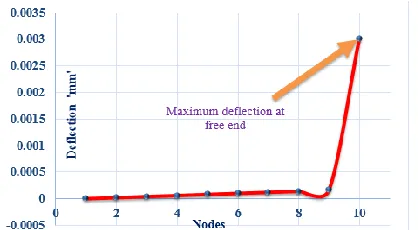
The ANSYS FEA software results and mathematical calculations are similar to each other. It is observed that the stress values obtained is similar to each other. At (Trial 1) the feed rate of 0.7 mm/ min, depth of cut 0.5 mm and spindle speed of 250 rpm, 201MPa of stress is obtained in ANSYS FEA software tool insert. The deflection pattern is shown in figure 9.1
Figure 8.1 – Deflection pattern of tool holder with tool
insert
At (Trial 1) feed rate of 0.7 mm/min, depth of cut of 0.5 mm and spindle speed of 250 rpm, 0.004 mm of deformation is observed at the free end of the beam. This deformation is reduced gradually and reached to zero at fixed end of cantilever beam. The deformation of tool holder and insert assembly is illustrated in figure 8.1whereas, in mathematical calculations, 199.41 Mpa is obtained. From these results, 99.20% of similarity is observed between ANSYS FEA software and mathematical calculations. These similarities are illustrated in figure 8.2
Figure 8.2 – Deflection pattern of tool holder with tool
insert
9.Conclusion:
The finite element method to determine the stress acting on the tool insert and the tool holder is discussed. The procedure followed to solve the finite element model in the ANSYS software is illustrated. The mathematical equations are solved to find the deflection and the stress acting on the tool insert. The results obtained from the ANSYS software is compared with the mathematical equations. In addition, the observations from the ANSYS software and mathematical equation results are discussed.
10.References:
[1] Ganesh Kumar, S & Thirunavukkarasu, V 2016, Investigation of Tool Wear and Optimization of Process Parameters in Turning of EN8 and EN 36 Steels ‗Asian Journal of Research In Social Sciences And Humanities‘. vol. 6, no.11, pp. 237 - 243,
[2] Ganesh Kumar, S, Thirunavukkarasu, V,
Sureshkumar, R, Venkatesh, S & Ramakrishnan, T 2019, ‗Investigation of Wear behaviour of Silicon Carbide Tool inserts and Titanium Nitride coated tool inserts in machining of EN8 steel, ‗International Journal of Mechanical Engineering and Technology‘, vol.10, no. 01, pp. 1862-1873 ,
[3] Kumar, R. S., Alexis, J., & Thangarasu, V. S. (2017). Optimization of high speed CNC end milling process of BSL 168 Aluminium composite for aeronautical applications. Transactions of the Canadian Society for Mechanical Engineering, 41(4), 609-625.
[4] Kumar, S. R., Alexis, J. S., & Thangarasu, V. S. (2017). Experimental Investigation of Influential Parameters in High Speed Machining of AMS 4205. Asian Journal of Research in Social Sciences and Humanities, 7(2), 508-523.
[5] Balasubramani, S., & Balaji, N. (2016). Investigations of vision inspection method for surface defects in image processing techniques-a review. Advances in Natural and Applied Sciences, 10(6 SE), 115-120.
[6] Balasubramani, S., Dhanabalakrishnan K.P.,
Balaji,N. (2015) Optimization of Machining
parameters in Aluminium HMMC using Response Surface Methodology. International journal of applied engineering research, 10(20), 19736-19739.
3231
[8] Sathish, K., Ramakrishnan, T., & Sathishkumar, S. (2016). Optimization of turning parameters to improve surface finish of 16 Mn Cr 5 material. Advances in Natural and Applied Sciences, 10(6 SE), 151-157. [9] Kumar, S., Alexis, J., & Thangarasu, V. S. (2016).
Prediction of machining parameters for A91060 in end
milling. Advances in Natural and Applied
Sciences, 10(6 SE), 157-164.
[10]P.Ashoka Varthanan, G.Gokilakrishnan , (2018). Simulation Based Swarm Intelligence to Generate Manufacturing-distribution Plan for a Bearing Industry under Uncertain Demand and Inventory Scenario.
International Journal of Pure and Applied
Mathematics, 119, 2117-2134.
[11]Xie, LJ, Schmidt, J, Schmidt, C & Biesinger, F, ‗2D FEM estimate of tool wear in turning operation‘, Wear, vol. 258, pp. 1479–1490.
[12]Attanasioa, A, Ceretti, E, Fiorentinoa, A, Cappellinia, C, Giardinib, C 2010, ‗Investigation and FEM-based simulation of tool wear in turning operationswith uncoated carbide tools‘, Wear, vol. 350, pp. 344-350
[13]Garcin,S Fouvry, S & Heredia, S 2015, ‗A FEM fretting map modeling: Effect of surface wear on crack nucleation‘, Wear, vol. 330-331, pp. 145-159.
[14]B.S. Prasad, M.P. Babu, Correlation between
vibration amplitude and tool wear in turning: Numerical and experimental analysis, Eng. Sci.
Tech., Int. J. (2016),
http://dx.doi.org/10.1016/j.jestch.2016.06.011
[15]Senthilkumar, N & Tamizharasan, T. (2014). Effect of Tool Geometry in Turning AISI 1045 Steel: Experimental Investigation and FEM Analysis, Arabian journal for science and Engineering. 39. 4963-4975. 10.1007/s13369-014-1054-2.
[16]Jitesh Kumar Singh,(2015), ―Optimization of the Cutting Parameters by Vibration Analysis of Cutting Tool‖, International Journal of Latest Trends in Engineering and Technology, Vol. 5 Issue 1 pp 270-275
[17]Mark J. Jackson, H. Zhang, and J. Ni,(2015), ―Machining Stability ―, Machining with Nanomaterials, DOI 10.1007/978-3-319-19009-9_2, pp No.37-54, [18]Nilesh Ambaji Jadhav,(2017), ―Vibration Analysis of
Lathe Machine Tool‖, International journal of research in engineering,science and technologies, Vol.2, No:7 pp 29-32