UCL
D IS C R E T E V A L U E -B A S E D B A N D W ID T H P R O V IS IO N IN G
&
R O U T IN G C O M P L E X IT Y IN IP N E T W O R K S
Thesis S ubm itted for th e Degree of
D octor of Philosophy of the U niversity of London
T h eod oros M ichalareas
D epartm ent of Electronic and Electrical Engineering
University College London
ProQuest Number: U641873
All rights reserved
INFORMATION TO ALL USERS
The quality of this reproduction is dependent upon the quality of the copy submitted.
In the unlikely event that the author did not send a complete manuscript and there are missing pages, these will be noted. Also, if material had to be removed,
a note will indicate the deletion.
uest.
ProQuest U641873
Published by ProQuest LLC(2015). Copyright of the Dissertation is held by the Author.
All rights reserved.
This work is protected against unauthorized copying under Title 17, United States Code. Microform Edition © ProQuest LLC.
ProQuest LLC
789 East Eisenhower Parkway P.O. Box 1346
Ewv<^ yovd<^ ]dov
A d q y â
Ka iHMa
To m y p a ren ts
Acknowledgem ents
I take great pleasure in opening this thesis by acknowledging those individuals and in stitu tio n s which made it possible for me to bring this thesis into being. Firstly I would like to th a n k my parents A thina, Elias and my b ro th er George for their su p p o rt and encouragem ent over my stu d en t years.
I would like to th a n k my supervisor Dr. Lionel Sacks who persuaded me into pursuing th is line of research, w riting this thesis and provided me w ith support when it was necessary. I would like also to th an k Paul Kirkby, who has been my industrial supervisor during my tim e in Nortel Networks, for the tru s t he p u t on me and the interesting discussions and ideas based on which th e first p a rt of this thesis has been formed.
D IS C R E T E V A L U E -B A S E D B A N D W ID T H P R O V IS IO N IN G
&
R O U T IN G C O M P L E X IT Y IN IP N E T W O R K S
T H E O D O R O S M IC H A L A R E A S
University College London,
D epartm ent of Electronic & Electrical Engineering, November 2002
Supervisor: Dr.Lionel Sacks, Lecturer in Telecom m unications Systems
A B S T R A C T
T he research presented in this thesis is concerned w ith the stru ctu re of th e solution space for th e IP routing problem for service layer packet networks overlayed to a D ynam ic O ptical T ransport Network which offers a Dynam ic B andw idth Provisioning service for Network Engineering purposes. The contributions of this thesis are:
a) A Value-Based B andw idth Allocation scheme and a respective algorithm for an O ptical T ran sp o rt Network which delivers dynam ic bandw idth provisioning services to its service layer networks in discrete ranges. This is a dynam ic scheme which expects from the service layer networks to declare their perception of value (utility) for the resources (lightpaths) they dem and. The value assigned to the resources depends on the business scenarios considered. The scheme supports b o th elastic and inelastic dem ands and it is based on the idea of weighted fairness. T his is an example of a D ynam ic B andw idth Provisioning scheme which can be utilised by service layer networks.
C on ten ts
A ck n ow led gem en ts ii
A b stra ct iv
Table o f C on ten ts iv
List o f F igu res viii
List o f T ables xii
List o f A b b rev ia tio n s x vi
1 In tro d u ctio n 1
1.1 D ynam ic T ransport L a y e r s ... 1
1.2 Thesis O rg a n is a tio n ... 2
1.3 O utline of Main C o n trib u tio n s ... 4
1.4 S u m m a r y ... 5
2 D isc r e te D yn am ic Transport N etw orks 7 2.1 In tr o d u c tio n ... 7
2.2 O ptical and Photonic T e c h n o lo g y ... 7
2.2.1 S D H /S O N E T ... 8
2.2.2 D W D M ... 11
2.2.3 IP r o u t e r s ... 14
2.2.4 Elem ent A ssu m p tio n s... 16
2.3 O ptical Network A rc h ite c tu re s ... 17
2.3.1 Overlay Model ... 17
2.3.2 Peer-to-Peer M o d e l ... 19
2.3.3 A rchitectural A ss u m p tio n s ... 21
2.4 Requirem ents on B andw idth P ro v isio n in g ... 22
2.4.1 Time-scales of Network E v e n ts ... 22
2.5 Dynam ic B andw idth Provisioning A p p lic a tio n s... 29
2.6 Cost of reservations versus overprovisioning... 31
2.7 U tility-based Discrete B andw idth A llo c a tio n ... 32
2.8 Sum m ary ... 33
D y n a m ic B a n d w id th A llo ca tio n B ackground 34 3.1 Microeconomic Theory B a c k g ro u n d ... 34
3.1.1 Basic C o n c e p t s ... 35
3.2 Fairness & U tility in N etw o rk in g ... 38
3.2.1 Max-Min F a irn e s s ... 38
3.2.2 Proportional & U tility F a i r n e s s ... 38
3.3 Engineering Framework for Dynamic P r o v is io n in g ... 41
3.3.1 Type of D e m a n d s ... 43
3.4 Sum m ary ... 44
T h e D y n a m ic D iscrete B a n d w id th A llo ca tio n A lg o rith m 45 4.1 Problem M o d e l ... 45
4.1.1 Network C urrency ... 47
4.1.2 W T P t y p e s ... 48
4.1.3 Formal Problem D e fin itio n ... 48
4.2 Basic A lg o rith m ... 49
4.2.1 Real-Valued A lgorithm D e s c r ip tio n ... 50
4.2.2 Basic A lgorithm Properties ... 51
4.2.3 Sim ulations & V a lid a tio n ... 54
4.2.4 Simple Conversion P o lic ie s ... 57
4.3 M ultiple Round B i d s ... 60
4.3.1 A lg o r ith m ... 62
4.3.2 Real-valued A llo c atio n s... 62
4.3.3 Producing Discrete A l l o c a t i o n s ... 65
4.4 S u m m a r y ... 67
C om parison w ith P r o -A ctiv e S egm en tation A ltern a tiv es 69 5.1 I n tr o d u c tio n ... 69
5.2 V irtual Resource Segm entation ... 69
5.2.1 MAX-MIN F a i r n e s s ... 70
5.2.2 The Progressive Filling A lg o rith m ... 72
5.2.3 FCFS Discrete A llocation A l g o r i t h m ... 73
5.3 N um erical E x p e rim e n ts ... 75
5.3.1 Tested A lgorithm s ... 75
5.3.2 Business S c e n a r io ... 75
5.3.3 M apping for M ultiple Round B i d s ... 77
5.3.4 Topology - R outing P l a n ... 78
5.3.6 Perform ance M e t r i c s ... 81
5.3.7 R e s u lts ... 82
5.4 C o n c lu s io n s ... 87
IP Service Layer R o u tin g 89 6.1 B a c k g r o u n d ... 90
6.2 U nicast IP R outing P r o b le m ... 90
6.2.1 IP longest m atch / Connectionless r o u t i n g ... 91
6.2.2 M P L S /P ath-oriented routing ... 93
6.3 W eighted G raph m o d e l ... 96
6.3.1 Sink Trees vs. P a t h s ... 97
6.3.2 C om putational C o m p lex ity... 98
6.3.3 D isa d v a n ta g e s... 99
6.4 S u m m a r y ... 105
R o u tin g L andscape M od el 106 7.1 I n tr o d u c tio n ...106
7.2 Fitness L a n d s c a p e s ... 108
7.2.1 A simple landscape for IP r o u t i n g ... 109
7.2.2 R outing Landscape M o d e l ... 112
7.2.3 R egular Configuration S p a c e s ... 114
7.2.4 Theoretical T o o l s ...116
7.3 R andom W a l k s ... 121
7.3.1 All Routes E n u m e r a t io n ... 122
7.3.2 Source-D estination R oute R andom S e le c tio n ... 129
7.4 Sum m ary ... 134
R o u tin g Landscape S tud ies 135 8.1 In tr o d u c tio n ...135
8.2 Traffic Scenarios & Fitness F u n c tio n s ...136
8.2.1 Traffic P a t t e r n s ... 136
8.2.2 Tem poral C h a ra c te ris tic s ... 139
8.2.3 Exam ined Fitness F u n c tio n s ...139
8.3 Sim ulation Techniques & Level of A b s t r a c t i o n ... 140
8.3.1 M easurem ents and P l o t s ... 142
8.4 R outing Landscapes of a Ring T o p o l o g y ...143
8.4.1 D e s c r i p t i o n ...143
8.4.2 Low Traffic Intensity Scenarios ... 144
8.4.3 Sum m ary S t a tis t ic s ...151
8.4.4 C orrelation between pairs of fitness fu n c tio n s ... 153
8.4.5 C orrelation between fitness functions and th e H am m ing distance 155 8.4.6 C haracteristic C orrelation L e n g t h ...155
8.5 R outing Landscapes of an ISP T o p o l o g y ...160
8.5.1 Variable Load E f fe c ts ... 162
8.5.2 Topological Changes E f f e c t s ...176
8.6 C o n c lu s io n s ... 192
9 C on clu d in g R em arks 194 9.1 The significance of th e configuration s p a c e ... 194
9.2 Thesis contributions ... 196
9.3 Suggestions for further r e s e a r c h ... 201
9.4 D is c u s s io n ... 202
A M ax-m in fairness and b o ttlen eck links 204 B A ll R o u te E n u m eration P r o o f o f C orrectness & C o m p leten ess 207 C R in g T opology R o u tin g L andscape M easu rem en ts 209 C .l Ring Topology Sum m ary Statistics & Fitness C o r r e l a t i o n s ...209
C.1.1 M edium Level Traffic Intensity ...209
C.1.2 High Level of Traffic I n t e n s i t y ... 211
C .l.3 S atu rated Level of Traffic I n t e n s i t y ... 213
C.2 Ring Topology A utocorrelation P l o t s ... 214
C.2.1 Medium Level Traffic Intensity ... 214
C .2.2 High Level of Traffic I n t e n s i t y ... 219
C.2.3 S atu rated Level of Traffic I n t e n s i t y ... 224
C.3 Ring Topology Fitness-H am m ing D istance Scatter P l o t s ... 227
C.3.1 Medium Level Traffic Intensity ...227
C.3.2 High Level of Traffic I n t e n s i t y ... 233
C.3.3 S atu rated Level of Traffic I n t e n s i t y ... 235
List o f Figures
2.1 SO N ET bit rate h i e r a r c h y ... 10 2.2 The components of a lambda s w i t c h... 13 2.3 The considered O T N Overlay A r c h ite c tu r e... 21 2.4 Processes and Tim e Scales in Network Control and M anagem ent . . . 22 2.5 A Proactive Architecture fo r Network M anagem ent ... 26 2.6 The Reactive Network M anagem ent A r c h ite c tu r e... 28
3.1 The Intelligent Controller selects the appropriate type of utility fu n c
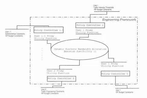
tion and the values of its associated parameters ... 37 3.2 The Engineering Framework built upon the D ynam ic Discrete B and
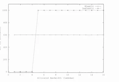
width Allocation algorithm and the Policy Intelligent Controllers . . . 41 3.3 The W T P map o f an elastic and an inelastic type o f d e m a n d... 43
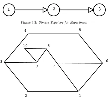
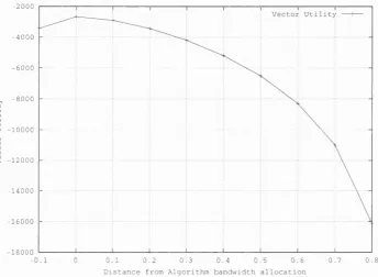
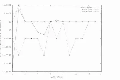
4.1 Pseudo Code Description of the Basic Algorithm fo r the Analog Problem 52 4.2 Simple Topology fo r E x p e r im e n t... 55 4.3 Complex Topology fo r E x p e r im e n t... 55 4.4 Utility fo r adjacent vectors o f allocated b a n d w id th... 56 4.5 Utilisation of every link fo r the solution produced by the basic algorithm 57 4.6 Utilisation o f every link fo r the possible p o l i c i e s... 59 4.7 The total utility fo r the real-valued and the respective floored allocation
vector fo r the complex topology ... 60 4.8 A n example Inelastic U ser’s Willingness To Pay fun ctio n o f lightpaths x 61 4.9 The organisation of tim e in epochs ... 62 4.10 U ser’s B id Readjustm ent B e h a v io u r... 64 4.11 Exam ple of the R eadjustm ent Behaviour of the A llocation Vector and
the Users B i d s ... 65
4.12 Pseudo-Code D escription of the algorithm fo r allocating spare wave
lengths ... 66
5.1 Virtually Segmentation P r i n c i p l e... 70 5.2 A simple case of M ax-m in fairness, fo r which the dem and of user 1
5.4 The Network Topology used in S im u la tio n s... 78 5.5 Total Value Forwarded fo r all considered algorithms, 60-40% Propor
tion of Inelastic-Elastic t r a f f i c 82
5.6 Total Value Forwarded fo r all considered algorithms, 25-75% Propor
tion of Inelastic-Elastic t r a f f i c 83
5.7 Total Value Forwarded fo r all considered algorithms, 10-90% Propor
tion of Inelastic-Elastic t r a f f i c 84
5.8 A lternative A lgorithm s Behaviour in term s of Rejected Users, for the case where 60 % of the resources are dedicated to Non Pre-E m ptive D e m a n d s... 85 5.9 A lternative Algorithm s Behaviour in term s of R ejected Users, for the
case where 25 % of the resources are dedicated to Non Pre-E m ptive D e m a n d s ... 86 5.10 A lternative Algorithm s Behaviour in term s of Rejected Users, for the
case where 10 % of the resources are dedicated to Non Pre-E m ptive D e m a n d s ... 86
6.1 The operation of an M P L S enabled network ... 95 6.2 Trees vs. Paths: A n example o f the difference in route organisation in
IP connectionless and M P L S n e t w o r k s... 98 6.3 A n example o f a traffic scenario fo r which separate efficient solutions
to the Network Engineering and IP routing problem once combined deteriorate the netw ork’s p e rfo rm a n c e... 103
7.1 The ”fis h ” topology and the configurations fo r the A -B r o u t e...109 7.2 The difference in the distribution of the total ranking m etric over the
A -B route configurations fo r the considered s c e n a r i o s...112
7.3 An example of the sim plest ring topology and its corresponding routing
configuration space organised in a hypercube stru ctu re of dim ension 2 (square) based on the H am m ing d i s t a n c e ... 114 7.4 A mesh network of 5 nodes, a route between any source-destination
pair is any ordered sequence of the rem aining nodes or a subset of them 115 7.5 T he form of the d a ta stru ctu re used to store all th e feasible routes
from the Enum eration A l g o r i t h m ... 123
7.6 Pseudo Code D escription of the E num eration A lgorithm for a Specific
Source-D estination P air ...124 7.7 In this example the need to reset the statu s of nodes from which the
process backtracks is d e m o n s t r a t e d ...126
7.8 A simple topology where the enum eration process has to perform 17
checks to complete the search for routes between source a and desti
nation d ...127
7.9 Pseudo Code D escription of the R andom Selection A lgorithm for a
7.10 An example of a simple topology w ith the probabilities of a link being selected according to the R andom P a th Selection A lgorithm and the
overall probability of a route being selected ...132
8.1 An example of an invalid route configuration for vanilla IP networks . 141
8.2 The sum m ary statistics (min,avg,max) of the network load m etric for
th e three p attern s in the low traffic intensity scenarios ... 145
8.3 Exam ples of characteristic histogram s of the achieved netw ork load from the R andom W alk in the low traffic intensity scenarios for differ ent traffic p a t t e r n s ...146 8.4 A utocorrelation plots of th e fitness values for th e Low Traffic Intensity
Scenario and the network load fitness f u n c t i o n ... 148 8.5 S catter Plots of Fitness vs. H am m ing distance of tested rou tin g con
figurations for the Low Traffic Intensity S c e n a rio ... 150 8.6 Difference between the average value of a m etric and its best (mini
mum) found value for a) packet loss, b) end-to-end delay and c) n et
work l o a d 152
8.7 Sum m ary of the C orrelation Coefficient between pairs of th e consid ered m etrics ...154 8.8 Sum m ary of the C orrelation Coefficient between the Individual M et
rics and th e selected neighbourhood relationship (H am m ing distance) 156 8.9 Sum m ary of the C haracteristic C orrelation Length of Individual M et
rics corresponding R outing L a n d s c a p e s ... 157 8.10 The base network topology used to evaluate th e changes in th e prop
erties of the R outing Configuration space as links are introduced or s u s p e n d e d ...160 8.11 The d istribution of source-destination pairs in term s of num ber of
feasible routes for th e ISP t o p o l o g y ... 161 8.12 Difference between the average value of a m etric and its best (mini
mum) found value for a) packet loss, b) end-to-end delay and c) n et
work l o a d 163
8.13 Sum m ary of the C orrelation Coefficient between pairs of the consid ered m etrics ...165 8.14 Sum m ary of the C orrelation Coefficient between th e Individual M et
rics and the selected neighbourhood relationship (H am m ing distance) 168
8.15 Sum m ary of the C haracteristic C orrelation Length of Individual M et rics corresponding R outing L a n d s c a p e s ... 171
C .l The sum m ary statistics (min,avg,max) for the three p a tte rn s and m et rics in the case of m oderate intensity s c e n a rio s ... 210 C.2 T he sum m ary statistics (min,avg,m ax) for the three p a tte rn s and m et
c.3
The sum m ary statistics (min,avg,max) for the three p a tte rn s and m et rics in the satu rated traffic intensity s c e n a r i o s ... 213C.4 A utocorrelation for the Delay M etric in scenarios of M oderate Traffic
I n t e n s i t y ... 215
C.5 A utocorrelation for the Packet Loss M etric in scenarios of M oderate
Traffic I n t e n s i t y ... 217
C.6 A utocorrelation for the Network Load M etric in scenarios of M oderate
Traffic I n t e n s i t y ... 218
C.7 A utocorrelation for the Delay M etric in scenarios of High Traffic Intensity220
C.8 A utocorrelation for the Loss M etric in scenarios of High Traffic Intensity221
C.9 A utocorrelation for the Network Load M etric in scenarios of High Traf
fic I n t e n s i t y ...223 C.IO A utocorrelation for the Delay M etric in scenarios of S a tu ra te d Traffic
I n t e n s i t y ... 225 C . l l A utocorrelation for the Loss M etric in scenarios of S a tu ra te d Traffic
I n t e n s i t y ...226 C.12 A utocorrelation for the Network Load M etric in scenarios of S atu rated
Traffic I n t e n s i t y ... 228 C.13 A utocorrelation and Scatter Plots for the Delay M etric in scenarios of
M oderate Traffic I n t e n s i t y ... 229 C.14 A utocorrelation and Scatter Plots for the Loss M etric in M oderate
Traffic Intensity S c e n a r i o s ... 231 C.15 A utocorrelation and Scatter Plots for the Network Load M etric in
M oderate Traffic Intensity S c e n ario s... 232 C.16 A utocorrelation and Scatter P lots for the Delay M etric in High Traffic
Intensity S c e n a r i o s ... 234 C.17 A utocorrelation and Scatter Plots for the Loss M etric in High Traffic
Intensity S c e n a r i o s ... 236 C.18 A utocorrelation and Scatter Plots for th e Network Load M etric in
High Traffic Intensity S c e n a r i o s ... 237 C.19 A utocorrelation and Scatter Plots for the Delay M etric in S atu rated
Traffic Intensity S c e n a r i o s ... 238 C.20 A utocorrelation and Scatter P lots for th e Loss M etric in S atu rated
Traffic Intensity S c e n a r i o s ... 239 C.21 A utocorrelation and Scatter Plots for th e Network Load M etric in
List o f Tables
2.1 M apping between SDH and SO N ET b it-rate hierarchies... 8
5.1 Traffic M atrix for C ontracted S e r v i c e ... 78 5.2 Sum m ary of Scenarios, P roportion of P re-E m p ted /N o n Pre-E m pted
U s e r s ... 80 5.3 The load for individual experim ents in term s of to ta l num ber of dem ands 80 5.4 Sum m ary of available t a r i f f s ... 80 5.5 Sum m ary of m apping of P riority Level of the two sup p o rted dynam ic
reservations to W T P tariffs ... 80
5.6 The average utility for all variants for the three sim ulated scenarios . 84
7.1 Scenario 1 (0% Background Traffic), A-B A lternative R outes R anking 110 7.2 Scenario 2 (10% Background Traffic), A-B A lternative R outes R anking 111 7.3 Scenario 3 (50% Background Traffic), A-B A lternative R outes R anking 111
8.1 Sum m ary of Traffic Intensity per E xperim ent for th e Ring Topology . 144
8.2 Sum m ary of the EDO m etric (network load) values for th e Low Traffic Intensity S c e n a r i o s ...149 8.3 Sum m ary of the C orrelation Coefficient between the p air of packet loss
and end-to-end delay fitness fu n c tio n s ... 177 8.4 Sum m ary of the C orrelation Coefficient between the p air of end-to-end
delay and to ta l network load fitness functions ... 177 8.5 Sum m ary of the C orrelation Coefficient between th e pair of to ta l n et
work load and packet loss fitness f u n c t i o n s ... 178 8.6 The difference (in secs) between the average and m inim um end-to-end
delay achieved from the tested route c o n f ig u r a tio n s ... 179 8.7 D elay/ H am m ing D istance C orrelation Coefficient for all three to p o
logical changes s c e n a r i o s ...179 8.8 End-to-end Delay R outing Landscapes C haracteristic C orrelation Length
for all three topological changes s c e n a rio s ... 180 8.9 The difference (in packets) between the average and m inim um packet
loss achieved from the tested route c o n f ig u r a tio n s ...180 8.10 Packet Loss/ H am m ing D istance C orrelation Coefficient for all three
8.11 Packet Loss R outing Landscapes C haracteristic C orrelation Length for all three topological changes s c e n a rio s ... 181 8.12 The difference (in bps) between the average and m inim um to ta l n et
work load achieved from the tested route c o n fig u ra tio n s ... 182 8.13 T otal network lo a d / H am m ing D istance C orrelation Coefficient for all
three topological changes s c e n a r i o s ...182 8.14 T otal network load R outing Landscapes C haracteristic C orrelation
Length for all three topological changes s c e n a r i o s ...182 8.15 Sum m ary of the C orrelation Coefficient between th e pair of packet loss
and end-to-end delay fitness fu n c tio n s ... 184 8.16 Sum m ary of the C orrelation Coefficient between the p air of end-to-end
delay and to ta l network load fitness functions ... 184 8.17 Sum m ary of the C orrelation Coefficient between the pair of to ta l n et
work load and packet loss fitness f u n c t i o n s ... 185 8.18 T he difference (in secs) between the average and m inim um end-to-end
delay achieved from the tested route c o n f ig u r a tio n s ... 185 8.19 D elay/ H am m ing D istance C orrelation Coefficient for all three topo
logical changes s c e n a r i o s ...186 8.20 E nd-to-end Delay R outing Landscapes C haracteristic C orrelation Length
for all three topological changes s c e n a rio s ... 186 8.21 The difference (in packets) between the average and m inim um packet
loss achieved from the tested route c o n f ig u r a tio n s ...187 8.22 Packet Loss/ H am m ing Distance C orrelation Coefficient for all three
topological changes sc e n a rio s ... 187 8.23 Packet Loss R outing Landscapes C haracteristic C orrelation Length
for all three topological changes s c e n a rio s ... 188 8.24 The difference (in bps) between the average and m inim um to ta l n et
work load achieved from the tested route c o n fig u ra tio n s ... 189 8.25 Total network lo a d / H am m ing D istance C orrelation Coefficient for all
three topological changes scenarios ...189 8.26 Total network load R outing Landscapes C haracteristic C orrelation
Length for all three topological changes s c e n a r i o s ...189
C .l C orrelation Coefficients between different m etrics for th e M oderate Traffic Intensity S c e n a r i o s ... 210 C.2 C orrelation Coefficients between different m etrics for the High Traffic
Intensity S c e n a r i o s ...212 C.3 C orrelation Coefficients between different m etrics for th e S atu rated
Traffic Intensity S c e n a r i o s ... 213 C.4 Sum m ary of th e FD C m etric (delay) values for th e M oderate Traffic
c.5
Sum m ary of the FD C m etric (packet loss) values for the M oderate Traffic Intensity S c e n a r i o s ... 216 C.6 Sum m ary of the FD C m etric (network load) values for th e M oderateTraffic Intensity S c e n a r i o s ... 219 C.7 Sum m ary of the FD C m etric (end-to-end delay) values for the High
Traffic Intensity S c e n a r i o s ... 219 C.8 Sum m ary of the FD C m etric (packet loss) values for th e High Traffic
Intensity S c e n a r i o s ... 222 C.9 Sum m ary of the FD C m etric (network load) values for the High Traffic
Intensity S c e n a r i o s ... 222 C.IO Sum m ary of the FD C m etric (end-to-end delay) values for the S atu
rated Traffic Intensity S c e n a r io s ... 224 C . l l Sum m ary of the FD C m etric (packet loss) values for the S atu rated
Traffic Intensity S c e n a r i o s ... 227 C.12 Sum m ary of the FD C m etric (network load) values for the S atu rated
List o f A bbreviations
A B R Available Bit R ate
ACTS Advanced Com m unications Technologies and Services
ADSL A sym m etric D igital Subscriber Line
ASON A utom atically Switched O ptical Network
ATM Asyncronous Transfer Mode
AS A utonom ous System
ASTN A utom atically Switched T ransport Network
CAC Connection Admission Control
CBQ Class based Queueing
CBR C onstant-bit R ate
C ID R Classless Interdom ain R outing
C R-LD P C onstraint-B ased R outing Label D istribution Protocol
DLMA D ynam ic L ight-Path M ulti-Bid A llocation algorithm
DS-1 D igital Service, level 1 (equivalent to 1.544 Mbps circuit capable of carrying
24 64Kbps voice circuits)
DSLAM DSL Access M ultiplexer
DW DM Dense W avelength Division M ultiplex
DCS D igital Cross-Connect System
E G P Exterion Gateway Protocol
FCFS First-C om e First-Served
FD C Fitness D istance C orrelation
FDM Frequency Division M ultiplex
F F C Fordward Equivalent Class
F T P File Transfer Protocol
GA G enetic A lgorithm
GM PLS Generalized M ultiprotocol Label Switching
IE T F Internet Engineering Task Force
IG P Interior Gateway Protocol
IP In tern et Protocol
IS-IS Interm ediate System to Interm ediate System
ISDN Integrated Services D igital Network
ISP In tern et Service Provider
LAN Local A rea Network
LSP Label Switched P a th
LSR Label Switching R outer
MPLS M ultiprotocol Label Switching
NMS Network M anagem ent System
NNI Network-to-Network Interface
OADM
O ptical Add-D rop M ultiplexerGAM O peration, A dm inistration, M aintenance
OC
O ptical GarrierODSI O ptical Domain Service Interconnect
O IF O ptical Internetw orking Forum
O M P O ptim ized M u ltiP ath
OSI O pen System Interconnect
O SP F Open Shortest P a th F irst
OTN O ptical T ransport Network
PD H Plesiochronous D igital Hierarchy
PLL Phased Locked Loop
PSTN Public Switched Telephone Network
PVC Perm anent V irtual C ircuit
QoS Q uality of Service
RED R andom Early Drop
R TP Real-Tim e T ransport Protocol
R SV P-T E Resource Reservation Protocol w ith Traffic Engineering E xtentions
SDH Syncronous D igital Hierarchy
SO N ET Synchronous O ptical Network
SP Shortest P ath
SPE Synchronous Payload Envelope
STS Syncronous T ransport Signal
STM Syncronous T ransport Module
TDM Tim e Division M ultiplex
TM N Telecom munications M anagem ent Network
TSP Travelling Salesman Problem
T C P Transmission Control Protocol
UBR Universal B roadband R outer
UD P User D atagram Protocol
UNI User-Network-Interface
VCI V irtual Channel Identifier
V P I V irtual P a th Identifier
VPN V irtual Private Network
V T V irtual T ributary
W DM W avelength Division M ultiplex
C hapter 1
In trod u ction
1.1
D ynam ic Transport Layers
In order to cope w ith the capacity dem ands imposed on the core network by the ex
plosive growth in d a ta communications, the tra n sp o rt layer currently utilises optical
W DM technology and the SDH hierarchy to satisfy a num ber of service layer net
works in an hierarchical approach to deliver the end-to-end service. A t the same tim e
new aggressive applications in term s of resources, either from th e academ ic commu
nity (for exam ple D ata GRID applications for High Energy Physics and Astronomy,
more examples can be found in [1, 2]) or business-oriented ones (for example B and
w idth Exchanges [3], T ransparent LAN and V PN services [4], D ynam ic Provisioning
services [5, 6]), dem and from the tra n sp o rt layer bandw idth provisioning and segre
gation capabilities in significantly smaller tim e scales th a n th e currently supported
ones.
The research presented in this thesis is concerned w ith th e use of an dynam ic
resource allocation scheme based on the idea of u tility and fairness in DW DM optical
networks the way they are realised today (SDH hierarchy) or th e near future (all
photonic networks) to provide such a dynam ic bandw idth provisioning ability for
custom er’s traffic. The thesis is also concerned w ith th e criteria which affect dynamic
bandw idth provisioning decisions in service layer networks. In p articu lar th e routing
algorithm used by the service layer networks (the exam ple of a service layer network
considered here is th a t of an IP network), its effectiveness and the convolution of
its operation w ith th a t of dynam ic bandw idth provisioning operations is examined,
1.2
T hesis Organisation
This thesis is organised in two parts. The first p a rt (C hapters 2-5) examines the
dynam ic discrete bandw idth allocation problem and the operation of the suggested
u tility-based engineering fram ework and algorithm s. The second p a rt (C hapters 6-8)
examines th e properties of th e IP routing problem as an exam ple of an optim isation
problem a t th e service layer which influences bandw idth provisioning actions and
their m erit, th e com binatorics-based model of the IP routing problem and its appli
cation.
Following this brief introduction, C hapter 2 provides a review of th e architecture
and th e basic elements of the model of T ransport Layer which is considered. The m ain
assum ptions ab o u t the elements capabilities, the service model and th e potential
applications supported, are presented. In p articular, atten tio n is draw n to examples
of recent applications and optical networking schemes as well as the current statu s of
the a rt in bandw idth provisioning. The chapter continues w ith a presentation of the
requirem ents of service layer networks from bandw idth provisioning mechanism s due
to th e tim e-scale of significant traffic related events and th eir netw ork m anagem ent
architecture. The chapter concludes w ith a discussion of criteria which can be used
to perform allocation of resources a t the tra n sp o rt layer.
B uilding upon the presentation of the T ransport Layer model C h ap ter 3 presents
the utility-inspired engineering framework proposed for allocating optical capacity
to the service layer networks and the fundam ental principles from the theory of
microeconomics and the application of fairness ideas to networking. The uses of
m ax-m in and proportionally fair algorithm s in other networking problem s for service
layer networks (IP and ATM) and the relative bibliography is reviewed. The chapter
concludes w ith a discussion of the type of dem ands which are supported by the
proposed engineering framework.
T he first p a rt of C hapter 4 presents the form al problem of the bandw idth allo
cation problem considered and the necessary expressive power th a t a User-Network
Interface (UNI) m ust have, in order to be used w ith the proposed engineering fram e
work. The second p art of this chapter presents the com ponents of th e Multiple Round
Bids algorithm which decides the allocation of bandw idth resources, an analysis of
its com putational complexity and how it can be integrated to a link-state protocol
C h ap ter 5 presents a num ber of results out of num erical experim ents which com
pare the Multiple Round Bids algorithm w ith an alternative allocation scheme, over
th e same fixed tra n sp o rt network topology and routing plan. T he chapter sta rts w ith
th e description of the alternative allocation scheme (which is based on segm entation
of th e resources and m ax-m in fairness) which is com pared to th e Multiple Round
Bids algorithm . The description of the m etrics used to evaluate th e algorithm s’ per
form ance are described and the chapter continues w ith the description of th e tested
scenarios and the results of th e numerical experim ents. Finally the chapter concludes
w ith a sum m ary of the proposed solution for the allocation of resources in a Discrete
D ynam ic O ptical T ransport network and an introduction to th e second p a rt of the
thesis which examines the properties of the IP routing problem as an example of a
service layer operation function which is influenced by bandw idth provisioning ac
tions and how it can be modelled to measure stru c tu ra l properties of the problem
which are influenced from topological or traffic p a tte rn changes.
C h ap ter 6 presents the graph-based view of the routing problem for Internet
Protocol (IP), M ultiprotocol Label Switching (MPLS) enabled service layer networks.
T he chapter also sum marises the state of the a rt routing algorithm s which are based
in this m odel and gives some examples of IP routing problem instances for which
th e graph model does not provide optim al, com putationally efficient solutions. This
challenging instances of the IP routing problem include the operation of an Internet
Service Provider (ISP) network over a fast-changing dynam ic topology (as in the case
of service layer network engineering applications operating using a tra n sp o rt layer
dynam ic bandw idth provisioning service).
C h ap ter 7 presents the R outing Landscape model of th e IP routing problem
based on a com binatorial optim isation view, inspired by sim ilar models developed in
the context of evolutionary biology (NK landscapes) or statistical mechanics (spin-
glass m odel). The chapter also presents a set of theoretical tools which can be
used to identify stru ctu ral properties of interest to the solution of th e problem from
heuristics, in specific traffic scenarios. The second p a rt of the chapter presents in
detail a sam pling m ethod, the necessary supporting algorithm s for its application on
instances of the routing problem over general network topologies and th eir properties.
C h ap ter 8 presents a num ber of num erical results for specific traffic scenarios.
The first p a rt of the chapter discusses the im p o rtan t properties of a traffic scenario,
the num erical experim ents. The second p art of the chapter presents th e results of
the experim ents organised in separate sections of each of th e two tested network
topologies. The chapter concludes sum m arising the results of th e application of the
R outing Landscape model. Finally, C hapter 9 concludes the thesis by sum m arising
the m ain findings of the research and provides suggestions for fu rth er resesarch work
building upon these results.
1.3
O utline o f M ain C ontributions
T he m ajor contributions resulting from this work can be sum m arised as follows:
• An engineering fram ework and a relative UNI for a Dynam ic O ptical T ransport
Network which allocates bandw idth resources to service layer networks based
on the idea of utility, for a variety of service models, including economic-based
ones (C hapter 3).
• The Multiple Round Bids algorithm which can be used as th e core of the en
gineering fram ework to com pute the bandw idth allocations in a distrib u ted or centralised m anner (C hapter 4).
• The R outing Landscape view of the IP, MPLS enabled service layer network
R outing Problem (com binatorics-based) and a num ber of theoretical tools which
m easure stru ctu ral properties of the problem (C hapter 6).
• The R andom Walk sam pling m ethod which can be used to generate a num
ber of routing configuration to be tested, and make possible th e evaluation of
the defined fitness functions and the properties of the corresponding R outing
Landscape (C hapter 7).
• Two supporting algorithm s of the R andom Walk operation over general network
topologies: a) A route enum eration algorithm for com puting all the feasible
loopless routes between any source-destination pair in general network topolo
gies, b) An algorithm for discovering a random selection of feasible routes from
the set of all the feasible routes for a given set of source-destination pairs.
T he contributions made during th e course of this research have led to the following
publications:
• Theodoros M ichalareas, ’’Com plexity Issues in M ulti-service Network M anage
m ent” , M ulti-Service Networks ’99 , R utherford Labs, A bington, July 1999,
UK.
• T. M ichalareas, L. Sacks, ” A nt-based M ulti-constrained routing and NK land
scapes” , 2nd International W orkshop on A nt A lgorithm s, ANTS 2000, Septem
ber 2000.
• T. M ichalareas, L. Sacks, ” Reactive Network M anagem ent A rchitectures &
R outing” , IF IP /IE E E International Symposium on In teg rated Network M an
agem ent IM2001, May 2001.
• T.M ichalareas, L.Sacks, P.Kirkby, ’’Value-Based D iscrete A llocation of Light-
P ath s in Dynam ic W DM Networks” IE EE Global C om m unications Conference,
GLOBECOM 2001.
T.M ichalareas, L.Sacks, ’’R andom Walks in R outing L andscapes” , London
Com m unication Symposium 2001, Septem ber 2001.
Chee Yeew Yong, T.M ichalareas, L.Sacks, ’’Network S tability w ith Delay Min
im isation in a QoS based O SPE Network” , Chee Yeew Yong, London Commu
nication Symposium 2001, Septem ber 2001.
1.4
Sum m ary
In this chapter th e m otivation and background for th e investigation of: a) appropriate
dynam ic bandw idth allocation schemes for the operation of th e Dynam ic Discrete
O ptical T ransport network and b) tools which can describe the stru c tu ra l properties
of specific instances of the service layer networks routing problem which influence and
is influenced by bandw idth provisioning actions, have been presented. T he structure
of the thesis and a sum m ary of the m ain contributions have been given. In the next
chapter a sum m ary of the capabilities and service architecture of m odern O ptical
C hapter 2
D iscrete D yn am ic Transport
N etw orks
2.1
Introduction
In this chapter the basic assum ptions concerning th e capabilities of the considered
O ptical T ransport Network (OTN) model and the special characteristics of the un
derlying technology th a t have to be taken into consideration, are described. In addi
tio n the architecture of the network, the role and the benefits of adding a dynamic
provisioning service are described.
A num ber of tra n sp o rt layer applications are described th a t can potentially use
such services along w ith the characteristics th a t expect to have available from the
core network. The chapter concludes w ith a first description of the allocation problem
for D ynam ic O ptical Networks and an outline of the principles th a t are used in this
thesis to solve it.
2.2
O ptical and P hotonic Technology
In this section the m ain capabilities of SO N E T /SD H and DW DM technologies, the
m ain candidates for terrestrial O ptical T ransport Networks, which are of interest for a
D ynam ic T ransport Network are described. This short description is an introduction
to the following discussion of the possible architectures for th e O ptical T ransport N et
SO N ET
O ptical C arrier Level
SONET
Electrical Equivalent
SDH D a ta rate
0 0 - 1 STS-1 - 51.840 Mbps
OC-3 STS-3 STM-1 155.520 Mbps
OC-12 STS-12 STM-4 622.080 Mbps
OC-48 STS-48 STM-16 2,488.320 Mbps
0 0 -1 9 2 STS-192 STM-48 9,953.280 Mbps
Table 2.1: M apping between SDH and SO N ET b it-rate hierarchies.
T he first exam ined technology is SD H /SO N ET.
2.2.1
S D H /S O N E T
In brief, S O N E T /SD H defines optical carrier (OC) levels and electrically equivalent
synchronous tra n sp o rt signals (STSs) for the fibre-optic based transm ission hierarchy
th a t can be used by carriers to offer services. It is a Tim e Division M ultiplexing tech
nology th a t is responsible for m anaging and shifting tim e-slots in very high speeds (up
to OC-768 in conjunction with DW DM ). For th e rest of this docum ent the SO N ET
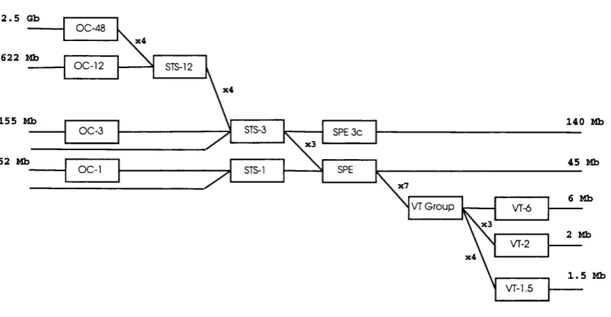
b it-rate hierarchy (as described in Figure-2.1) is used and th e SO N E T /SD H tech
nology is referred to as SO N ET (which currently is more popular w ith IP routers
m anufacturers). The IT U -T (0.709 recom m endation, [7]) term inology (which is SDH
specific) is used for describing the basic elem ents of th e network. T he capabilities
described and the assum ptions made hold for b o th variants (Table-2.1 for th e corre
spondent m appings to SDH).
The traffic entering the core of an SO N ET network is expected to m eet a closely
controlled synchronisation specification [8, 9]. Service ad aptors are used for non-
com pliant services, ranging from voice to high-speed d a ta and video, so th a t they
can tran sp o rted over SONET. All inputs are eventually converted to a base form at of
a Synchronous T ransport Signal (or STS) STS-1 signal (51.84Mbps or higher). Lower
speed inputs such as D S -ls /T -ls (1.544Mbps or the equivalent of 24 64Kbps tele
phony circuit in the N orth Am erica TDM hierarchy) are first b it- or byte-m ultiplexed
into v irtu al trib u taries (as in Figure-2.1) th a t themselves are packaged to STS-1 sig
nals. Several synchronous S T S-ls are then m ultiplexed (byte interleaved) together
one or more) [10]. Any STS-n frame above STS-3 in a SO N ET network contains 4
equivalent S T S -(J) sub-frames or n STS-1 subframes. Every fram e has a Payload
section (Synchronous Payload Envelope or SPE) th a t is available for the tra n sp o rt of
d a ta and an overhead section th a t is used to perform th e O peration & M anagem ent
Functions for th e network.
T he efficiency of the transm ission carrier from the SO N ET hierarchy is fairly high.
T he SO N ET hierarchy achieves a very high utilisation of the optical carriers, 96.67%
of the transm ission capacity is available for custom ers’ traffic for channelised in ter
faces. Some of the STS-n frames are available in their concatenated form indicated
as STS-nc (e.g. STS-12c). An STS-nc frame has the same payload as th e equiva
lent STS-n fram e b u t the payload is not treated as the outcom e of a byte interleave
operation of m ultiple STS-1 signals bu t as a single frame. In concatenated frames
some of the overhead bytes are ignored (but cannot be used for payload) and some
of th e 0A M functions (O peration, A dm inistration, M anagem ent) are sim pler (the
ones relates to payload’s pointers ). Such frames are used in cases in which operators
are interested in using STS-n frames as a single point-to-point network connection
ra th e r th a t th a n m ultiplexed signals of STM-1 of lower rates traffic (as in Internet
Service P rovider’s case which is examined in §2.2.3). The concatenated form can
further improve the utilisation rate of the transm ission capacity b u t a t the cost of
losing the ability to virtually select subfram es’ payload out of high rate STS signals.
S O N E T netw ork elem en ts
Typical elem ents in a SO N ET network are the following:
Service A d ap tors are responsible for adapting th e custom er asynchronous offered traffic. A service ad ap to r m aps the signal into the payload envelope of the
STS-1 or virtual trib u tary (VT). New services and signals can be tran sp o rted
by adding new service adaptors a t the edge of the SO N ET network.
A D M Add Drop M ultiplexers are responsible for interleaving isochronous traffic to higher fram e-rates to achieve economy benefits.
E lectrica l-to -O p tica l C onverters and R egen erators are responsible for utilis ing the fibre capacity and tran sm ittin g the optical signal in long distances w ith
a very small error probability. In DWDM networks these are Electrical-to-
2.5 6b
x 4
622 Mb
x 4
155 Mb 140 Mb
x 3
52 Mb 45 Mb
x 7
6 Mb
x 3
2 Mb
x 4
1.5 Mb
STS-12
STS-1
VT-2 OC-1
O C -3
VT G roup SPE
SPE 3 c
VT-6 O C -48
STS-3 O C -12
Figure 2.1: SO N ET bit rate hierarchy
D C S D igital Cross-Connects Systems accept as in p u t various carrier rates and switch them in tim e (moving d a ta from one slot/ subfram e to another w ithin the same
basic frame) and space (moving frames between different ports).
All th e active elements in a SO N ET network use Phase Locked Loops (PLL)
to keep th eir reference clock signals synchronised w ith S tratu m 1 level precision,
approxim ately 0.000001 p arts per m inute (ppm) [8].
S O N E T services
T he m ain services th a t a SO N ET tra n sp o rt network offers are th e following:
P o in t-to -P o in t H igh B a n d w id th P ro v isio n SO N E T /S D H networks can support very high bandw idth services w ith very low b it error and m inim al latency.
G room in g Asynchronous traffic and lower bandw idth services from legacy tra n sp o rt networks (PDH) are supported.
P r o te c tio n The SO N ET network cross-connects can be deployed in ring topolo gies to provide protected point-to-point circuit connections thro u gh back-up
rings.The A utom ated P rotection Switching Scheme provides fast switch overs
The SO N ET cross-connects have available vendor-specific A PIs and open inter
faces th a t im plem ent the necessary functionality of GAM (defined in [11],[12],[13]
and conforming to the IT U -T TM N M. series specifications). In practise while the
capabilities for a more dynam ic bandw idth provisioning exist in the SO N ET spec
ification, m ost of the deployed networks are based on a centralised vendor-specific
Network M anagem ent System (NMS), th a t has been engineered w ith sem i-static,
relatively long Service Level Agreements (SLAs) or tra d itio n a l telephony trunk-like
needs in m ind (changes and provisioning tim escale is in the order of m onths).
A lthough SO N E T /SD H has been a carrier invention (Bell Labs) w ith a focus
in an overlay architecture (section §2.3) and survivability, the SO N ET based ports
th a t are available for IP routers w ith m inim al service ad ap to r function (Packets over
SO N ET, [14]) could be used in a peer-to-peer architecture providing point-to-point
dynam ically reconfigurable virtual channels (in §2.2.3).
2.2.2
D W D M
W avelength Division M ultiplexing (WDM) refers to th e use of distinct wavelengths
(or lam bdas) over an optical fibre to im plem ent separate channels. Every lam bda
can tra n sm it a very high speeds of d a ta (2.5, 10 or 40Gbps). An optical fibre can
carry several channels in parallel, each on a p articu lar wavelength. T he num ber
of wavelengths th a t each fibre can carry sim ultaneously is lim ited by th e physical
characteristics of the fibre and the state of optical technology used to combine these
wavelengths onto the fibre and isolate them off th e fibre. Dense W DM (DWDM)
refers to the technology th a t allows for a relatively large num ber of wavelengths to
be exploited. This lim it used to be at the order of 10 in p ast years and is currently
of the order of 100 and growing. C urrent estim ation in th e future of DW DM tech
nology raise this lim it to approxim ately 3000 wavelengths per fibre [15]. DWDM has
been viewed as an m ultiplexing m ethod for th e optical m edium and a cost-reduction
technology, and a technology th a t can be used to utilise the huge bandw idth of the
fibre m edium , satisfying and bandw idth requirem ents of th e end-users.
D W D M basic com p on en ts
In a DWDM network every fibre link has a num ber of wavelengths available and the
end-to-end optical circuit is term ed a lightpath and it can be allocated a num ber of lam bdas w orth of bandw idth. The routing of the lig h tp ath is perform ed by a wavelength
routing algorithm s which selects which fibre links have to be used and decides which
lam bdas have to be used from each link. The basic com ponents in a W DM network
th a t are used for the establishm ent and term ination of lightpaths are th e following:
a d d / d r o p m u ltip l e x e r (A D M ) is an optical system th a t is used to modify the
flow of traffic through a fibre a t a routing node. An ADM passes traffic on
certain wavelengths through w ithout interruption or optoelectronic conversions
(conversions to electronic form and back to optical form), while traffic on other
wavelengths is term inated optically, th a t is, converted to electronic form (the
wavelength is dropped ). Some wavelengths can also be added, th a t is, traffic
is injected a t this node using those wavelengths [16].
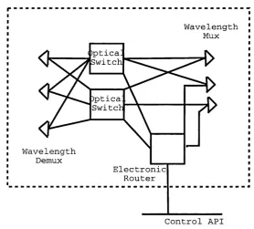
W a v e le n g th R o u t e r ( W R ) is a more powerful com ponents th a n an ADM. It takes
in a signal at each of the wavelengths at an in p u t p o rt, and routes it to a p ar
ticular o u tp u t p o rt, independent of the other wavelengths. A W R w ith N input
and N o u tp u t ports capable of handling W wavelengths can be tho u g h t of as W
independent N x N switches. These switches have to be preceded by a wave
length dem ultiplexer and followed by a wavelength m ultiplexer to im plem ent
a W R, as shown in Figure-2.2. Thus a W R can cross-connect the different
wavelengths from the input to the o u tp u t, where th e connection p a tte rn of
each wavelength is independent of the others. For this reason, it is sometimes
also called a wavelength cross-connect. This description highlights th e routing
function of the W R sim ilar to th a t of a DCS in the SO N ET technology. Of
course, some of the wavelengths on some of the in p u t po rts m ay be carrying
signals which are destined for an access node directly connected to the W R in
question. In this case, th a t signal has to be extracted from the optical medium
a t this W R. To do this, it is necessary to term in ate th a t p articu lar wavelength,
convert the d a ta into electronic form, and deliver it to a higher layer. There
may also be signals on some wavelengths which need to be forwarded to other
nodes on a different wavelength. The wavelength has to be term in ated in this
case as well, the signal extracted to electronic form, converted back to optical
form in th e other wavelength and injected to an o u tp u t p ort. To highlight the
Wavelength Router
W a v e l e n g t h M u x Optical
^ S w i t c h
W a v e l e n g t h D e m u x
E l e c t r o n i c R o u t e r
C o n t r o l A P I
Figure 2.2: The components of a lambda switch
switching) as well as forwarding via conversion to electronic form and back to
optical (more like conventional routing), they are som etim es also called Wave
length R outing Switches (WRS, [17]) or O ptical Cross-connects (OXC).
W avelen gth C onverter is an optical device th a t can be used in an optical router, to convert the wavelength a channel is being carried on. W ith o u t wavelength
conversion, an incoming signal from one p o rt pi on, say, the wavelength i can
be optically switched (w ithout interm ediate optoelectronic conversions) to any
p o rt pj, b u t only on the wavelength i. W ith wavelength conversion capability,
this signal could be could be optically switched to any p o rt pj on any wave
length k. T h a t is, wavelength conversion allows a clear optical channel to be
carried on different wavelengths on different physical links. Different levels
of wavelength conversion capability are possible. Full wavelength conversion
capability implies th a t any input wavelength m ay be converted to any other
wavelength. Lim ited wavelength conversion denotes th a t each in p u t wavelength
may be converted to any of a specific set of wavelengths, which is not th e set
length conversion is th a t the virtual topology th a t can be im plem ented is less
constrained, since the wavelength continuity constraint is removed [18, 19].
DW DM technology is used in tran sp o rt networks to perform bandwidth provision
ing point-to-point in very high transm ission speeds (2.5, 10 or 40 G bps per wave
length) and grooming of lower speed connections. One im p o rtan t difference w ith
SO N E T /SD H is th a t protection is not considered yet in DW DM. T he development
of DW DM technology has given rise to an extended m ultiplexing hierarchy to support
the higher speeds (0 0 -1 9 2 for lOGbps, OC-768 for 40Gbps). available [7] and the
idea of th e O ptical T ransport Network (OTN, [20]) and A utom ated Switched Trans
p o rt Network (A STN /A SO N , [21]) th a t define the necessary control mechanisms for
th e establishm ent and release of network connection in DW DM network.
2.2.3
IP routers
A lthough trad itio n ally IP routers are considered p a rt of th e service layer using tran s
p o rt layer bearer services, the recent IE T F initiative to define and prom ote the
Generalised MPLS protocols (GMPLS [2 2, 23]) and operators, research community,
equipm ent m anufacturers support may change this view. M PLS is a p a th oriented
technology for perform ing label based switching in IP networks inspired by ATM.
Once a packet enters a MPLS dom ain it is assigned a label or in M PLS term inology it
is assigned to a Forward Equivalent Class (EEC) and is m arked w ith its correspond
ing label. In M PLS-enabled nodes the packet is forwarded according to the value of
its label and th e inform ation stored in locally stored tables. These switching tables
also hold new values for the label values carried by th e packets. These tables are
u p d ated by signalling protocols th a t establish p aths for possible source-destination
pairs. MPLS enables routing configuration th a t can deviate by the single-tree source
node oriented stru ctu re of IP hop-by-hop routing and allows for th e establishm ent
of explicit p ath s for Traffic Engineering purposes [24].
The m ain idea for GMPLS is to provide th e necessary extension to the path-
oriented MPLS protocol so th a t MPLS enabled routers th a t have SD H /S O N E T or
DW DM in p u t/o u tp u t ports can have a view of the optical properties of the links and
establish routes according to those. GMPLS is based on th e premise th a t MPLS can
be used as the control plane for different switching applications, including:
(for example in SO N ET connections)
• Frequency Division M ultiplexing (FDM) where labels are a ttrib u te d to frequen
cies (or lam bdas) (for example in DWDM lightpaths)
• Space-division m ultiplexing where labels are a ttrib u te d to po rts (for example
in O ptical Cross Connects)
Generalised MPLS is a set of protocols rath er th a n a single protocol. It is an ex
tension of previous IF T F work on MPLS for traffic engineering of IP networks [25].
GM PLS generalises the MPLS signalling protocols to allow th e same protocols, with
extensions, to be used to control optical switches as well as packet switches. The set
of GM PLS protocols includes:
• Link M anagem ent Protocol for neighbour discovery [26]
• Extensions to th e popular IP routing protocols O SP F [27] and IS-IS [28] for
link-status dissem ination
• Extensions to R SV P-TE [29] and CR-LD P [30] for p a th m anagem ent and con
trol
Since the concept of tim e slot or specific frequency doesn’t exist for th e service
layer oriented MPLS, only the notion of adjacency between point A and point B,
extensions are required for the routing descriptor to include inform ation w ith regards
to the used tim e-slo t/lam b d a and other useful d a ta such as th e type of th e protection
scheme required, the capacity required, bit error rate, etc. Since there have been two
label d istrib u tio n / signalling m ethods defined for th e d istrib u tio n of MPLS related
inform ation in IP networks, the extensions for D W D M /SO N E T networks are being
m ade for b o th of them (CR-LD P and R SV P-TE).
D W D M /S O N E T p orts in IP routers
T he S D H /S O N E T ports supported can be either channelised or concatenated. More
specifically the channelised interfaces available to OG-48 and OC-192 rates can dy
nam ically create virtu al interfaces w ith portions of th e physical p o rt frame rate. Also
in term s of control capabilities, although the focus up to recently have been semi
and it possible to be controlled by a dynam ically driven signalling protocol (like
GM PLS [22], or ASTN, [21]).
T he IP SO N ET interfaces can be used in two different ways. They can be used in
either an IP service layer configuration connecting to a SO N ET netw ork in an overlay
configuration where they utilise the tra n sp o rt netw ork’s S tratu m 1 clock signal for
synchronisation or they can be user to a peer-to-peer configuration connecting IP
routers back-to-back w ith dark fibre. The IP routers in th a t case usually utilise an
internal less accurate clock of 20 ppm for synchronisation which is th e m inimum
precision the SD H /SO N E T equipm ent has been tested and dem onstrated to inter
o perate with.
The DW DM interfaces can operate in sim ilar ways, in an overlay or a peer-to-peer
m ode, w ith the capability to dynam ically segment th eir available capacity. In the
DW DM case and the SO N E T /SD H peer-to-peer mode th e ability to operate over
resilient rings is lost. In order to provide restoration and protection capabilities th a t
are not available through DW DM new mechanisms a t the IP layer are employed
(Fast Switchover and Graceful restart mechanisms, [31, 32]).
2.2.4
E lem ent A ssu m p tion s
From the above description of the properties of SO N ET, DW DM and IP over O ptical
networks the common properties for the network elem ents of th e O TN independent
of the technology used are the following:
E x trem e Low Error In b o th cases th e underlying optical transm ission technology
offers very sm all (10“ ^° transm ission error rates).
H igh C ap acity Every individual link in a O TN network can offer transm ission capacity from 155Mbps to 40Gbps.
C oarse V irtu a l D iscrete S egm en tation In all cases th e network resources can be v irtually segmented to a num ber of sm aller logical links. Unlike ATM the
transm ission hierarchy in bo th cases defines a strict hierarchy w ith a small
num ber of possible capacity levels (com pared to th e to ta l capacity of the link)
for each individual logical link.
connection oriented.
S w itc h in g B oth technologies support cross-connects th a t can be used to change the
v irtu al segments used to form a light-path, in an auto m ated, protocol supported
way.
R e c o n f ig u r a b le P o r t s In b oth cases the term in atin g /o rig in atin g p o rts can be re
configured to increase or decrease the num ber of v irtu al segment available.
In the following two sections (§2.3, §2.4) th e two proposed service architectures
th a t are proposed to organise these element into a functional netw ork and two m an
agem ent architecture approaches to control them and reconfigure them are examined
for completeness. The assumed model of th e network is based on th e overlay opti
cal network architecture and can accom odate bo th network m anagem ent approaches
described.
2.3
O ptical N etw ork A rchitectures
T he different proposed architectures for th e O ptical T ranspo rt Network reflect the
two different views on networking from the d a ta network and th e tra n sp o rt network
operators. On th e one hand the d a ta network operators are interested in attain in g
control and m anaging network resources based on the dom inant service layer tech
nology IP. The tra n sp o rt network operators on the other hand, are interested in the
separation between the m anagem ent of the core network resources and the m anage
m ent of the service layer custom ers’ equipm ent. The result is th a t two different views
on the architecture of an OTN have been developed , one th a t favours routers, and
an o th er th a t favours optical switches. They are called, respectively, th e overlay and
th e peer.
2.3.1 Overlay M odel
In this model, the optical network cloud, m ade up of Sonet/S D H , DW DM links
and optical switching systems, provides connection services to IP routers and other
client devices attached to th e network. In this client-server netw ork architecture,
there are two different layers of the network, isolated from each other, and dynamic
model, routers or service layer switches require connection from th e optical network
through an appropriate interface (m anagem ent or control), and the optical network
is responsible for perform ing the necessary connection adm ission control, tra n sp o rt
layer routing and allocation of resources. These requests can be fairly sophisticated,
describing the size of the circuit w ith a p articu lar grade of restoration. The key
characteristic is th a t the service layer network devices do not have any knowledge or
access to the internals of the tra n sp o rt network.
The benefits of this model have led to its early endorsem ent by th e O ptical
D om ain Service Interconnect C oalition(O D SI), th e O ptical Internetw orking Forum
(O IF), and th e International Telecom munication Union (ITU ). T he m ain advantages
of the overlay m ode :
• T he optical layer comprises subnetworks w ith well defined interfaces to client
layers.
• It allows each subnetwork to evolve independently
• Innovation can evolve in each subnet independently
• It allows interoperability w ith older infrastructure
• It provides IP, ATM, and SO N ET interoperability using open interfaces
• O ptical network topology and resource inform ation is kept secure
In order to build the overlay architecture, stan d ard network interfaces are re
quired. Two type of interfaces are developed, one set for accessing the network from
an external network device and one set for accessing the network from an internal
network device. The User Network Interface (UNI) provides a signalling mechanism
between th e service layer and the tra n sp o rt layer dom ain, while the Network-to-
Network Interface (NNI) provides a m ethod of com m unication and signalling among
subnetworks w ithin an optical tra n sp o rt network.
The UNI allows attached clients of an optical network to establish optical connec
tions dynam ically across the optical cloud, using a neighbour-discovery mechanism
and a service-discovery mechanism. Thus, devices attach ed to an optical network will