Systematic Design of Space-Time Trellis Codes
for Diversity and Coding Advantages
Zoltan Safar
Department of Electrical and Computer Engineering, University of Maryland, College Park, MD 20742, USA Email: [email protected]
K. J. Ray Liu
Department of Electrical and Computer Engineering, University of Maryland, College Park, MD 20742, USA Email: [email protected]
Received 15 June 2001 and in revised form 17 January 2002
The emerging need for high data rate wireless services has raised considerable interest in space-time coding. In this work, we propose a systematic code construction method that jointly considers diversity advantage and coding advantage for an arbitrary number of transmit antennas and any memoryless constellation. Our approach is to directly assign channel symbols to transmit antennas at different states by exploiting the properties of the state transitions in the trellis. The code construction problem is reduced to a combinatorial optimization problem and a computationally efficient suboptimal solution is proposed. The flexibil-ity of the method is demonstrated by designing space-time trellis codes for QPSK, 8PSK, 16PSK, asymmetric QPSK and 4ASK constellations. Space-time code construction for a large number of transmit antennas (6, 8, and 10) is also considered. The simu-lations show that our design procedure results in codes that outperform the ones constructed by previously existing methods. The achievable performance gain is governed by the distance structure of the chosen constellation.
Keywords and phrases:space-time codes, trellis codes, transmit diversity, wireless communications.
1. INTRODUCTION
In wireless communications, the transmitted signal under-goes severe distortion due to multipath fading and interfer-ence from other users. The design of communication systems that offer reliable transmission at high data rates is a chal-lenging task in such circumstances. To combat the adverse ef-fects of the radio signal propagation environment, several di-versity techniques have been developed [1]. These techniques offer increased protection against the channel-induced dis-tortion by providing multiple versions of the transmitted sig-nal to the receiver.
Time diversity, for example, represents redundancy in the time domain. A form of time diversity, channel coding com-bined with interleaving, adds redundancy with a certain al-gebraic structure that can be exploited to detect and cor-rect transmission errors [2]. Another widely used diversity technique is spatial diversity, which adds redundancy in the spatial domain. By building a system with multiple transmit and/or receive antennas and making use of the larger number of signal propagation paths between the transmitter and the receiver, the quality of the wireless link can also be improved [1].
Information-theoretic works [3, 4, 5, 6, 7] have shown that the capacity of fading channels is substantially increased when using multiple transmit and/or receive antennas. The results of [6] for the quasi-static, flat Rayleigh fading chan-nel model can be summarized as follows. If the chanchan-nel gains between the transmit and receive antennas are assumed to be known at the receiver side, the channel capacity is approxi-mately proportional to the minimum of the number of trans-mit and receive antennas.
Space-time (ST) trellis codes have been proposed as a means to exploit the potential for capacity increase in multi-antenna systems. The performance criteria were derived in [8, 9], characterizing the ST codes with two quantities: the di-versity advantage, which describes the asymptotic error rate decrease as a function of the signal-to-noise ratio (SNR), and the coding advantage, which determines the vertical shift of the error performance curve. In [9], the authors proposed design rules for two transmit antennas to achieve the maxi-mum diversity advantage. They also derived a lower bound on the complexity of the encoder and the decoder for the desired diversity advantage and data throughput. This lower bound states that in order to achieve a diversity advantage of
the encoder and the decoder must have at leastNmin =BK−1
states.
The repetition coded delay diversity scheme described in [10] was the first systematic design rule for an arbitrary number of transmit antennas. Using this method, ST codes achieving full diversity advantage can be designed for arbi-trary constellations and encoders withNminstates. This work
also introduced the idea of zero symmetry to constrain com-puter search for ST codes with more than two antennas.
In [11], the design problem was transformed into the bi-nary domain. The code design was based on the finite field counterpart of the ST code performance criteria for full spa-tial diversity. The authors proposed code design procedures for an arbitrary number of transmit antennas and an arbi-trary number of states, but only for BPSK and QPSK constel-lations. Moreover, the design methods in [10, 11] for full di-versity advantage uniquely determine the ST codes, not leav-ing room to improve the codleav-ing advantage.
In this paper, we propose a systematic design method based on an alternative approach: we exploit the structure of the trellis to design ST codes that provide full diversity ad-vantage for an arbitrary number of transmit antennas, ar-bitrary number of encoder states (as long as it satisfies the lower bound) and arbitrary memoryless constellations. Our method can be treated as a generalization of the results of [9, 10]. The design rules for full diversity advantage do not specify the ST codes completely, offering the possibility to further optimize for coding advantage.
Moreover, we develop a code design procedure that befits from this possibility for the important special case of en-coders withNminstates. Based on the design rules for
diver-sity advantage, we reduce the code construction problem to a combinatorial optimization problem and propose a compu-tationally efficient suboptimal solution. It seems that this is the first work that considers systematic code design for both diversity advantage and coding advantage.
The rest of the paper is organized as follows. Section 2 introduces the mathematical model of the communication system. The performance criteria for ST trellis codes are also described in this section. The code construction method will be developed in Sections 3 and 4. Section 5 describes specific ST code construction examples, and the simulation results demonstrating the performance of these codes are provided in Section 6. Finally, we draw some conclusions in Section 7.
2. SYSTEM MODEL AND PERFORMANCE CRITERIA
In this section, the mathematical model of the wireless com-munication system under study is described. The notation used throughout this paper is introduced. Then, we summa-rize the relevant results of the previous works and briefly re-state the performance criteria derived in [8, 9]. These criteria serve as a basis for the development of our systematic design procedure.
Consider a wireless communication system withK
trans-mit and Lreceive antennas (the transmit antennas are
in-dexed byk,k ∈ {0,1, . . . , K−1}, and the receive antennas are indexed byl,l ∈ {0,1, . . . , L−1}). The input bit stream
is divided into bsbit long blocks, formingB-ary (B = 2bs) source symbols. The ST encoder works as a finite state ma-chine with N states: it takes the currentbs bit long source symbol, bt (bt ∈ {0,1, . . . , B −1}) at discrete time t(t = 0,1,2,3, . . .), and governed by this input and the current state,St (St ∈ {0,1, . . . , N−1}), it moves to the next state,
St+1. During this state transition, the encoder outputsK B
-ary channel symbol indices, one for each transmit antenna. We denote byik(S
t, bt) the channel symbol index for trans-mit antennak, generated during the state transition fromSt when the current input source symbol isbt. We also use the channel symbol index vector, defined as
iSt, bt=
i0S
t, bt, i1St, bt, . . . , iK−1St, bt T
. (1)
These channel symbol indices select one of the B diff
er-ent waveforms for each antenna, and the selected wave-forms are transmitted simultaneously through the transmit antennas. In the sequel,c(i) will be the complex baseband
vector-space representation of the ith passband waveform
(i ∈ {0,1, . . . , B−1}).c(i) will also be referred to as theith constellation point or channel symbol. All the constellations are assumed to be normalized so that the average energy of the constellation is unity (if the channel symbols are equally likely).c(ik(S
t, bt)) will denote the constellation point out-put by antennakwhen the current state isStand the current input isbt. The vector of channel symbols is given by
cSt, bt
=ci0S t, bt
, ci1S t, bt
, . . . , ciK−1S t, bt
T
.
(2)
The transmission medium is assumed to be flat (fre-quency nonselective), quasi-static, Rayleigh fading chan-nel. The quasi-static property means that the channel re-mains constant over a certain time, called frame period, and changes independently from one frame to the other.αkl will represent the path gain from transmit antennakto re-ceive antenna l. These path gains are modeled as indepen-dent, complex, zero mean, circularly symmetric Gaussian random variables with unit variance. Furthermore, some ad-ditional assumptions are made to facilitate the analysis. First, the receiver has knowledge of the αkl propagation coeffi -cients. Second, the receiver is perfectly synchronized with the transmitter.
Based on the above assumptions, after down-conversion, matched filtering and sampling, the received signal at receive antennal, at discrete timetcan be expressed as [9]
rl t=
K−1
k=0
E0
Kαklc
ikS
t, bt+zlt=slt+zlt, (3)
whereE0is the total average transmission energy per
trans-mitted source symbol (each transmit antenna transmits the channel symbols withE0/Kaverage transmit energy),sltand
zl
t stand for the received signal and noise components, re-spectively, andzl
N0. Consequently, the average SNR per source symbol at
re-Assume that the previously described transmitter sends
T(T > K)B-ary source symbols to the receiver. The ST en-coder, while encoding the data, goes through the following sequence of states:
S0−−−→b0 S1−−−→b1 S2−−−→ · · ·b2 −−−−→bT−2 ST−1−−−−→bT−1 ST. (5)
In words, the encoder starts in S0, takes the first inputbs -tuple, b0, moves to S1, and so on. As a result of this state
transition sequence, the encoder produces the channel sym-bol vector sequence
The above vector sequence can be arranged into aK×T ma-trix,C:
The decoder, due to decoding errors, goes through a dif-ferent sequence of states,
producing the erroneously decoded source symbol sequence
{b
We can defineD, the channel symbol difference matrix
asD = C−C, and aK ×K matrixAasA=DDH. Let A
(andD) be of rankm. SinceAis Hermitian and nonnegative definite, its eigenvalues are real and nonnegative. Let λ1 ≥
λ2 ≥ · · · ≥ λm be the nonzero eigenvalues of A. Given the earlier described channel model, it can be shown [9] that the probability that the decoder erroneously decodesCifCwas sent can be upper bounded as
PC|C≤
The performance criteria [8, 9] were derived to minimize
P(C|C) for a givenE0andN0:
(1)Design for full spatial diversity (rank criterion): the ma-trixDmust be of full row rank for any distinctCandC ma-trices. (Then we havem=K.) In this case, a diversity advan-tage ofKLhas been achieved.
(2)Design for coding advantage (determinant criterion): the minimum determinant ofAtaken over all distinctCand
C matrices must be as large as possible. If the minimum
determinant isγ, then a coding advantage of √Kγhas been
achieved.
Note that the above performance criteria are not con-structive, that is, they do not provide a systematic method to construct good ST codes.
3. DESIGN FOR DIVERSITY ADVANTAGE
3.1. Trellis structure analysis
The goal of this subsection is to analyze the algebraic struc-ture of the trellis of the ST encoder and find closed form expressions that relate the state sequence {St}to the start-ing stateS0and the input source symbol sequence{bt}. The additions and the multiplications are assumed to be stan-dard integer operations. The modulo operation will always be written explicitly to avoid ambiguity.
Assume that the encoder hasN = RBK+p−1 states, with
R = 2r,B =2bs,bs > 0,p ≥0, and 0 ≤ r < bs. Therefore,
it satisfies the lower bound of [9] for desired diversity
ad-vantage ofK withB-ary source symbols. Any large enough
power of 2 number can be put into this form; the purpose of this representation is to make the analytical treatment eas-ier. The numberNis simply decomposed into the product of two numbers: the first number,Ris less thanB, and the other number is a power ofB.
The state transition of the encoder at timetis determined by the previous state,St−1(St−1 ∈ {0,1, . . . , N−1}), and the
previousB-ary input,bt−1(bt−1∈ {0,1, . . . , B−1}).
Analyti-cally it can be described as
St=BSt−1+bt−1
modN
=BSt−1modRBK+p−2+bt−1.
(11)
It is shown in the appendix that we can unfold this recursion and obtain a closed form expression forSt, 1≤t≤K+p−1:
Based on these analytical results, we can deduce some im-portant information about the error path structure of the trellis. Assume that the first decoding error occurs at state
S0, that is, the correct and the erroneous paths diverge atS0,
in-000,100,200,300 020,120,220,320 030,130,230,330 010,110,210,310 003,103,203,303 023,123,223,323 033,133,233,333 013,113,213,313 001,101,201,301 021,121,221,321 031,131,231,331 011,111,211,311 002,102,202,302 022,122,222,322 032,132,232,332 012,112,212,312
t=0 t=1 t=2 t=3 t=4
330 030
001
111
000
022
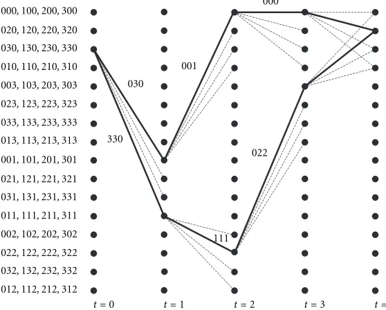
Figure1: Example ST code for three antennas, QPSK.
0≤r < bs, the shortest error path is at leastKlong, that is, the
paths diverging atS0can merge only atSKor later.
3.2. Design for full diversity
Using formulas (12) and (13), we derive design rules that guarantee that the ST trellis code achieves full diversity ad-vantage. First, we obtain sufficient conditions to make the channel symbol difference matrix corresponding to the first
K long error path segment of the first error event full rank. Afterwards, the results will be extended to arbitrary channel symbol difference matrices.
In the ST encoder,Bchannel symbol index vectors are
assigned to each state, according to the branches emanat-ing from that state. The current source symbol selects one of them, and thekth (k =0,1, . . . , K−1) index of the cho-sen vector determines the constellation point for antennak. Figure 1 depicts an example ST code for three antennas and QPSK constellation (K = 3, B =4, N = 16). In this case, if the current state is state 2 and the value of the current source symbol is 3, the ST encoder selects the third channel symbol index vector, [3,3,0]T, and moves to state 11. The zeroth, first, and second antennas will transmit the channel symbols corresponding to the indices 3, 3, and 0, respectively.
Suppose that the transmitter sends T (T > K) source symbols. Without loss of generality, we can assume that the first decoding error event occurs at S0, making the correct
and the decoded paths diverge. For now, we are concerned
only about the first K long segment of all error paths of
lengthKor larger immediately after the first error event has occured. Our goal is to construct theK×Kchannel symbol difference matrixD1, defined as
D1=
cS0, b0
−cS0, b0
,cS1, b1
−c(S1, b1), . . . ,c
SK−1, bK−1
−cSK−1, bK−1
, (14)
in such a way that it is of full rank for any possible correct and erroneous paths through the trellis. Our method is to
makeD1 upper triangular with nonzero diagonal elements.
We exclude all ST codes that do not produce upper triangular
D1matrices, so the resulting ST codes may not be optimal.
However, what we gain is a problem formulation that leads to a simple solution.
TheS0→S1state transition is special since both the
cor-rect and the erroneous paths start at the same state. The goal is to set the zeroth entry of the zeroth column of D1 to a
nonzero value and to zero out the rest of the entries in that column. This can be achieved by the following conditions that form the first half of the design rules:
(1a) The zeroth indices of the channel symbol index vectors at the same state must be different.
(1b) The remaining indices of the channel symbol index vectors at the same state must be the same.
In our example, assume that theb0=0 (top) path is the
correct path and theb0=3 (bottom) path is the erroneously
decoded path. The channel symbol index vectors [0,3,0]T and [3,3,0]T have different zeroth indices, but the first and second indices are the same; therefore, the zeroth column of theD1matrix will be [1 +j,0,0]T.
For the rest of the state transitions St → St+1, t =
1,2, . . . , K−1, the objective is to set thetth entry of thetth column ofD1to a nonzero value and to zero out all the
en-tries below thetth entry in that column. To facilitate the ex-planation, we introduce the following definitions.
Definition1. Aleveltgroupis a collection of all destination states that can be reached at state transitiontfrom a given
S0 starting state through all possible b0, b1, . . . , bt−1 input
Definition2. Asubgroup of a leveltgroupis a collection of all destination states that can be reached at state transitiont
from a givenS0starting state and a givenb0starting branch
through all possibleb1, b2, . . . , bt−1input sequences.
In order to effectively use these defnitions in the design procedure, we need to describe the relationship between the encoder states and the groups and subgroups at different lev-els. Equation (12) expresses the state transition at time t,
t = 1,2, . . . , K −1, as a function of the starting state,S0,
and the source symbol sequenceb0, b1, . . . , bt−1. BecauseS0
is kept constant in Definition 1 for all possibleb0, b1, . . . , bt−1
sequences, we can eliminate the effect of the starting state by taking modulo Bt of both sides of (12). Therefore, the expression StmodBt will describe howSt depends on the
b0, b1, . . . , bt−1 sequence for an arbitrary, but fixed,S0
start-ing state. From (12), we obtain
StmodBt=Bt−1b0+Bt−2b1+· · ·+Bbt−2+bt−1. (15)
The above quantity can be thought of as a t digit B-ary
number. As the input B-tuples (b0, b1, . . . , bt−1) vary from
(0,0, . . . ,0) to (B−1, B−1, . . . , B−1), the value ofStmodBt varies from 0 toBt−1. Consequently, fort=1,2, . . . , K−1, any leveltgroup starts at statemsuch thatmmodBt=0 and consists ofBtconsecutive states.
Similarly,S0andb0are kept constant in Definition 2, so
the expressionStmodBt−1will describe howStchanges as a function ofb1, b2, . . . , bt−1. From (12), we have
StmodBt−1=Bt−2b1+Bt−3b2+· · ·+Bbt−2+bt−1. (16)
The above quantity can be thought of as a t−1 digitB
-ary number. As the inputB-tuples (b1, b2, . . . , bt−1) vary from
(0,0, . . . ,0) to (B−1, B−1, . . . , B−1), the value ofStmodBt−1 varies from 0 to Bt−1−1. Therefore, we conclude that for
t = 1,2, . . . , K−1, any subgroup of a leveltgroup starts at statemsuch thatmmodBt−1=0 and consists ofBt−1
consec-utive states.
Sinceb0∈ {0,1, . . . , B−1}, by definition every group
con-sists ofBsubgroups according to differentb0 values. From
(15), it can be seen that different b0 values result in
dis-joint sets ofStmodBtvalues as theB-tuples (b1, b2, . . . , bt−1)
vary from (0,0, . . . ,0) to (B−1, B−1, . . . , B−1). Thus, for
t =1,2, . . . , K−1, every leveltgroup consists ofBdisjoint subgroups. We index the subgroups within a group by the ze-roth source symbol, soStbelongs to theb0th subgroup and
Stbelongs to theb0th subgroup of the same leveltgroup.
In the case of the ST code of Figure 1, the level 1 groups consist of 4 consecutive states, starting at states 0,4,8, and 12. The subgroups consist of only one state. The only level 2 group is comprised of all the 16 states, and its subgroups are made up of 4 consecutive states, starting at states 0,4,8, and 12. The level 1 and level 2 groups and subgroups of the exam-ple ST code are depicted in Figures 2b and 2c, respectively.
Because both the correct and the erroneous paths start from the same state (S0 = S0), at state transition t, t =
1,2, . . . , K−1, both the correct path (St) and the erroneous
path (St) go through states that belong to the same levelt
group. This means that if themth indices of the channel sym-bol index vectors at states belonging to any leveltgroup are the same, then themth entry of thetth column ofD1 will
be zero. For example, in Figure 1, states 8 and 11 belong to the same level 1 group, and the second indices of the channel symbol index vectors [0,0,1]Tand [1,1,1]Tare the same. As
a consequence, the first column of the D1 matrix becomes
[1−j,1−j,0]T.
Since the first decoding error occurs atS0 (b0 = b0), at
state transition t,t = 1,2, . . . , K −1, the correct path (St) and the erroneous path (St) go through states that belong to different subgroups of the same leveltgroup. We can take advantage of this fact as follows: if the mth indices of the channel symbol index vectors at states belonging to diff er-ent subgroups of the same level tgroup are different, then themth entry of thetth column ofD1 will be nonzero. To
continue the example, states 0 and 13 belong to different sub-groups of the same (only) level 2 group. The second indices of the channel symbol index vectors [0,0,0]T and [0,2,2]T are different, so the second column of the matrixD1will be
[0,2,2]T.
Having produced the methods to place zero and nonzero entries into the matrixD1, we can state the second half of the
design rules:
(2a) Fort = 1,2, . . . , K −1, thetth indices of the channel symbol index vectors at states belonging to the same
subgroup of any leveltgroup must be the same, and
they must be different from thetth indices of the chan-nel symbol index vectors at states belonging to any other subgroup of that group.
(2b) Fort=1,2, . . . , K−2, the (t+1)st,(t+2)nd, . . . ,(K−1)st indices of the channel symbol index vectors at states belonging to the same leveltgroup must be the same. (Note that criterion (2b) is omitted fort=K−1.)
After making the matrix D1 full rank, the final task is
to show that the channel symbol difference matrixD corre-sponding to the transmission of allTsource symbols is also of full rank. The matrixDcan be decomposed as
D=D1,D2 , (17)
whereD1is defined in (14), andD2 is aK×(T −K)
ma-trix. SinceD2is arbitrary, this description includes the cases
when the correct and the decoded paths diverge and merge several times. From linear algebra, it is well known that ifD1
is of full rank, thenDis also of full (row) rank. Consequently, the design rules will produce codes that provide full diversity advantage.
0
Figure2: The group/subgroup structure of the example ST code.
group. Moreover, the second indices of the channel symbol index vectors in each level 1 group are the same. Finally, rule (2a) fort=2 is illustrated in Figure 2c. In each subgroup of the only level 2 group, the second indices of the channel sym-bol index vectors are the same, and they are different from the second indices of the index vectors of the other subgroups.
By observing the group/subgroup structure of the state transitions in the trellis, we can make the design rules in-dependent of the state evolution in time. The above design method describes relationships between channel symbol in-dices of different antennas at different states. Furthermore, these design rules do not fully determine the state-channel symbol assignment, providing the possibility to further opti-mize for coding gain.
Design rules (1a) and (1b) are similar to the design rules described in [9] for two transmit antennas. Therefore, our approach can be treated as a generalization of the method of [9] to an arbitrary number of transmit antennas.
4. DESIGN FOR CODING ADVANTAGE
In general, finding the best way to assign channel symbol in-dices to antennas and states is not a simple task. IfN > Nmin,
the shortest error path is longer thanK, so the correspond-ing code difference matrix does not have any special struc-ture. As a consequence, expressing the minimum
determi-nant of the code becomes very difficult. However, in the
N =Nmin =BK−1case (i.e.,r =0 andp =0), it is possible
to find an efficient method to maximize the coding gain, so
from now on, it is assumed that the encoder hasNminstates.
The channel symbol difference matrix corresponding to the firstKlong segment of the error paths after the first de-coding error has occured is the matrixD1, defined in (14).
It is square and upper triangular, so its determinant is the product of its diagonal elements:
detD1
Considering the transmission of all T source symbols,
and using the decomposition of (17), the matrixA=DDH, whose minimum determinant is to be maximized, can be ex-pressed as
A=D1D1H+D2D2H=A1+A2, (20)
where A2 = D2D2H. By construction, both A1 andA2 are
Hermitian and nonnegative definite. To continue the argu-ment, we will use the following theorem from linear algebra
i0
Figure3: Example ST code template for three antennas, 4-ary con-stellations.
definite matrices. Moreover, let λ0(X) ≥ λ1(X) ≥ · · · ≥
λK−1(X) denote the real and nonnegative eigenvalues ofX.
Then we have the following inequality fori=0,1, . . . , K−1:
λi(X+Y)≥λi(X) +λK−1(Y). (21)
In our case, (21) becomes
λi
From this, we can conclude thatγ, the determinant ofA, sat-isfies the inequality
We can fix an arbitrary correct path and pick an arbi-trary error path that is longer thanKstate transitions. Both
this error path and the error path corresponding to theK
long error event that starts from the same S0 starting state
and the sameb0 starting branch go through states that
be-long to the same subgroups of the same groups, resulting in
D1matrices with the same diagonal elements (design rules
(1a) and (2a)). Therefore, for any error event that is longer than K state transitions, it is possible to find aK long er-ror event with the same det(A1) value. As a consequence of
this observation and (24), γmin, the minimum determinant
of the code, can be determined by taking into account only the shortest error events:
The minimum is taken over all possibleKlong correct and
incorrect paths.
TheSkandSkstate transition sequences can also be de-scribed by making use of the group/subgroup structure of the trellis. The results of Section 3 allow us to map the firstK
long segment of the correct and erroneous paths of the first decoding error event onto different groups and subgroups of states. Toward this end, we introduce a channel symbol index based notation that does not explicitly depend on the state transition sequence.
Let i0
l,i0l ∈ {0,1, . . . , B−1}, be the zeroth indices of the channel symbol index vectors at the same state corre-sponding to source symbol l (l ∈ {0,1, . . . , B−1}). For simplicity, it is assumed that the 0th indices of the chan-nel symbol index vectors at different states corresponding to the same source symbol values are the same. Moreover, let ik
l, k = 1,2, . . . , K −1, ikl ∈ {0,1, . . . , B −1}, denote the kth indices of the channel symbol index vectors at the states belonging to thelth subgroup of the same levelkgroup (l∈ {0,1, . . . , B−1}). According to design rules (1a) and (2a),
Applying the design method of Section 3 and using the above index notation, we can create a “template” ST code. It is called template because the design rules for full spa-tial diversity do not specify the codes completely. It con-tains channel symbol index templates at each state for each antenna. For the ST code example of Figure 1, this tem-plate is shown in Figure 3. Here, the 4-tuples (i0
0, i01, i02, i03),
(i1
0, i11, i12, i13), and (i20, i21, i22, i23) can be any permutations of the
numbers (0,1,2,3). The ST code will achieve full diversity advantage for arbitrary permutations. The objective is to find those permutations that result in maximizing the coding ad-vantage of the ST code.
Using the simplified notationl=b0andm=b0(l=m),
it was shown earlier that fork=1,2, . . . , K−1,Skbelongs to thelth subgroup andSkbelongs to themth subgroup of the same levelkgroup. Therefore, using the above defined index notation, we can make the following substitutions:
ikSk, bk=ikl, ikSk, bk=ikm, fork=0,1, . . . , K−1. (26)
can be rewritten as
γmin= min l,m∈{0,1,...,B−1}
l<m K−1
k=0
cikl−cikm 2
. (27)
Thel < mcondition can be used since the squared distance function is symmetric in its arguments. The final goal is to
maximize the minimum determinant. Therefore, if ΩB
de-notes the set of all permutations of the numbers 0,1, . . . , B−1, andσk∈Ω
B(k=0,1, . . . , K−1) stands for a particular per-mutation (ik
0, ik1, . . . , ikB−1), thenγmin∗ , the optimal minimum
determinant, can be expressed as
γmin∗ = max σ0,σ1,...,σK−1
min
l,m∈{0,1,...,B−1}
l<m K−1
k=0
cik
l
−cik m
2
. (28)
This combinatorial optimization problem can be interpreted as follows. The design rules for diversity advantage andK
permutations of the numbers 0,1, . . . , B−1 together uniquely determine the code. The task is to find those permutations
that offer the largest minimum determinant. Because the
numbers 0,1, . . . , B−1 can be arranged inB! different ways, the size of the search space is (B!)K. This means that exhaus-tive search may be impractical in certain cases. For example, ifB=16 andK=5, the search has to be done over approxi-mately 4·1066possibilities.
To get around this complexity growth, we propose a sub-optimal approach that offers a practical solution. The basic idea is to restrict the search space such that the resulting com-plexity is not prohibitive. Toward this end, we define the no-tion of the parametric permutano-tion funcno-tion.
The parametric permutation function is a function that generates a subset of all possible permutations of the num-bers 0,1, . . . , B−1. Different parameters produce different permutations, so the problem will be reduced to a search for the best parameter. Therefore, the parametric permutation function is required to have the following properties:
• It must be a bijective map: for any parameter, it must map the set{0,1, . . . , B−1}onto itself in a one-to-one manner.
• Two different parameters must generate two different permutations.
In the sequel, we will use the notation i2 = ψB(n, i1) for
one possible realization of the parametric permutation
func-tion. The value n is the parameter to be optimized (n ∈
{1,2, . . . , B−1}), andi1andi2are the input and output
in-dices, respectively (i1, i2∈ {0,1, . . . , B−1}). Note that the
ob-viousψB(n, i1)=(ni1) modB, for oddn, is not a good choice
because it does not “shuffle” the indices well enough. The output index is generated according to the follow-ing description. The input indexi1and the parameternare
treated as binary vector representations of two field elements in GF(B)=GF(2bs). These field elements are multiplied
to-gether according to field arithmetic, and the output indexi2
will be the binary vector representation of the product. For example, forB=4, the field GF(4) can be built up usingα, a
Table1: Element representation in GF(4).
Value Binary vector Polynomial Power Power
representation representation representation
0 00 0 0 –
1 01 1 α0 0
2 10 α α1 1
3 11 α+ 1 α2 2
Table2: The generated permutations.
i1 n=1 n=2 n=3
0 0 0 0
1 1 2 3
2 2 3 1
3 3 1 2
root of the primitive polynomial p(x)=x2+x+ 1, as shown
in Table 1. In this case, the functionψ4(·,·) will generate the
permutations given in Table 2. The table entries are the func-tion values for different input index and parameter values.
The above example shows two general properties of the function ψB(·,·). First, the zero index always maps to itself:
ψB(n,0) = 0. Second, if the parameter is one, the function value is equal to the input index value:ψB(1, i1) =i1. Since
the above definition of the parametric permutation func-tion exploits the algebraic properties of the underlying Ga-lois field, it can be easily seen that it has the required prop-erties. Moreover, the elements of a Galois field can also be represented as powers of a primitive element, providing the possibility of efficient implementation by turning the multi-plications into moduloB−1 additions.
Replacing the permutation operation by the parametric permutation function, the optimization problem reduces to
γ∗min=n0,nmax1,...,nK−1
∈{1,2,...,B−1}
min
l,m∈{0,1,...,B−1}
l<m K−1
k=0
cψB
nk, l
−cψB
nk, m 2
.
(29)
To findγ∗min, we only have to search over (B−1)K possibili-ties. In the case of theB=16,K=5 example, the size of the search space will be less than 8·105. Once then∗
0, n∗1, . . . , n∗K−1
parameter values that maximize the minimum determinant have been calculated, the channel symbol indices can be de-termined as
ik l =ψB
n∗k, l, k=0,1, . . . , K−1, l=0,1, . . . , B−1.
(30)
5. CODE DESIGN EXAMPLES
we describe the relationship between the repetition coded de-lay diversity scheme of [10] and our approach. The dede-lay di-versity scheme was chosen as a basis for comparison because, to our knowledge, this is the only existing procedure that can be used to construct ST trellis codes for any number of trans-mit antennas and any constellation. Then, we give specific code design examples.
The delay diversity scheme is a special case of our
de-sign method. For B = 2 (e.g., the BPSK constellation) and
N =Nmin, the two methods are equivalent: the design rules
for full spatial diversity uniquely determine the code. For
B > 2, the delay diversity scheme corresponds ton∗k = 1 (k=0,1, . . . , K−1), which leads toik
l =l(k=0,1, . . . , K−1,
l =0,1, . . . , B−1). In [10], it was shown that, if∆denotes the minimum Euclidean distance of the chosen constellation, then the minimum determinant of the resulting delay diver-sity ST code will beγD
min=∆2K.
To characterize the theoretical performance improve-ment of our method over the delay diversity ST codes, we will use the relative coding advantage, β, defined as β =
K
γmin∗ /γminD . This quantity describes the normalized vertical
shift between the two error performance curves as the SNR becomes large.
5.1. Code design forB-ary PSK
In case ofB-ary PSK modulation, the squared distance be-tween constellation pointslandm(l, m∈ {0,1, . . . , B−1}) is given by
d2(l, m)=c(l)−c(m)2=4 sin2
(l−m)π B
. (31)
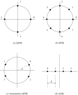
A pictorial representation of the QPSK and 8PSK constel-lations are shown in Figures 4a and 4b. Using (31) to ex-press the minimum determinant of the code, the optimiza-tion problem becomes
γmin∗ =n0,nmax1,...,n
K−1 ∈{1,2,...,B−1}
min
l,m∈{0,1,...,B−1}
l<m 4K
×K−1
k=0
sin2
ψBnk, l−ψBnk, mπ
B
.
(32)
If this optimization procedure is used for three antennas (K =3) with QPSK (B=4,N =16), and Table 2 is used to generate the parametric permutation function values, then the result of the optimization will ben∗0 = 1,n∗1 = 2, and
n∗2=3 withγ∗min=16. Note that this maximum is not unique:
several other sets of{n∗k}values exist. This is not surprising because of the symmetry of the QPSK constellation and the commutativity of multiplication. The obtained permuta-tions are: (i0
0, i01, i02, i03)=(0,1,2,3), (i10, i11, i12, i31)=(0,2,3,1),
and (i2
0, i21, i22, i32) = (0,3,1,2). These permutations generate
the ST code example depicted in Figure 1 . The minimum determinant of the corresponding delay diversity ST code isγD
min =∆6 =8, resulting in a relative coding advantage of
β=1.26. For this particular case, the authors of [13] found a better code (γmin =32) through computer search. However,
exhaustive search cannot be used to find good ST codes for a larger number of transmit antennas and larger constellation sizes because of its computational complexity.
For easy description, we need to find an efficient and con-cise representation for our ST codes. In [14], a generator ma-trix based approach was used. However, some of our codes belong to a more general class of ST codes because they can-not be described by generator matrices. To see this, consider the ST code example of Figure 1. The constellation point for antenna 2 is determined by the two most significant bits of the 4 bit state information. We denote these two bits by s2
ands3(s2, s3∈ {0,1}). In order to be able to describe this ST
code by a generator matrix, the functionF(s2, s3), defined as
Fs2, s3=a2s2+a3s3mod 4, (33)
should generate the indices 0, 3, 1, 2 in this order for somea2
anda3(a2, a3∈ {0,1,2,3}). We trivially haveF(0,0)=0. The
F(1,0)=3 relation forcesa2to be 3. Similarly,a3has to be 1,
as a consequence ofF(0,1)=1. Finally, the function will re-sult inF(1,1)=0, which is not the desired value 2. Therefore, this ST code cannot be put in a generator matrix form. The possibly large number of encoder states prevents us from us-ing the trellis diagram, so the channel symbol index permu-tations will be used to describe the ST codes. Note that this representation is unique, and due to the regular structure of the proposed ST codes, it is easy to design simple encoders withO(KB) hardware complexity.
Using the same procedure, ST codes for three transmit antennas (K =3), 8PSK (B = 8, N = 64), and 16PSK (B =
16, N = 256) constellations have also been constructed. In the 8PSK case, the channel symbol index permutations
i0
0, i01, i02, i03, i04, i05, i06, i07
=(0,1,2,3,4,5,6,7),
i1
0, i11, i12, i13, i14, i15, i16, i17)=(0,1,2,3,4,5,6,7),
i20, i21, i22, i23, i24, i25, i26, i27
=(0,2,4,6,3,1,7,5)
(34)
are one of the possible sets of permutations that maximize the objective function, yielding the minimum determinant
γ∗min = 0.6863. The minimum determinant of the delay
di-versity scheme with the same design parameters is γD
min =
0.2010. These coding advantage values yield β = 1.51. For the 16PSK constellation, our design method resulted in the ST code given by the channel symbol indices
i00, i01, i02,i03, i04, i05, i06, i07,i08, i09, i010, i011, i012, i013, i014, i015
=(0,1,2,3,4,5,6,7,8,9,10,11,12,13,14,15),
i1
0, i11, i12, i13, i14, i15, i16, i17,i18, i19, i110, i111, i112, i113, i114, i115
=(0,2,4,6,8,10,12,14,3,1,7,5,11,9,15,13),
i2
0, i21, i22,i23, i24, i25, i26, i27,i28, i29, i210, i211, i212, i213, i214, i215
=(0,4,8,12,3,7,11,15,6,2,14,10,5,1,13,9).
Table3: ST codes for QPSK modulation.
K N Permutations γ∗min γD
min Decoding
depth
2 4 P1, P1 4 4 25
4 64 P1, P1, P2, P3 32 16 25
6 1024 P1, P1, P2, P2, P3, P3 256 64 25
8 214 P
1, P1, P1, P1, 1024 256 35 P2, P2, P3, P3
10 218 P
1, P1, P1, P1, P2, 8192 1024 45 P2, P2, P3, P3, P3
The minimum determinant of this code isγmin∗ =0.110105,
while the delay diversity construction givesγD
min=0.003529.
The relative coding advantage isβ=3.15.
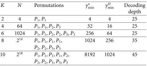
The reduced computational complexity of the proposed design procedure allowed us to construct ST codes for a large number of transmit antennas. Table 3 contains the brief de-scription of the codes designed for QPSK constellation. The symbolsP1,P2, andP3 denote the permutations (0,1,2,3),
(0,2,3,1), and (0,3,1,2), respectively. The permutations are assigned to transmit antennas from left to right. According to this notation, the three antenna ST code example of Figure 1 can be described as:P1, P2, P3. Theγ∗minandγDminvalues are
also shown.
5.2. Code design for asymmetric QPSK
The next two examples employ constellations that are not used in current wireless communication systems, but they can illustrate the flexibility of the proposed design method. The first ST code was constructed for four transmit antennas (K=4) and asymmetric QPSK modulation (B=4, N =64). The pictorial representation of the asymmetric QPSK con-stellation can be observed in Figure 4c. The parameter α, which is the angle between the signal points and the real axis, was set toπ/8 (rad). The Euclidean distances between two ar-bitrary constellation points cannot be expressed in a closed form, but they can be easily calculated. The minimum dis-tance of the constellation is∆=2 sinα=0.7654. The opti-mization procedure results in
i00, i01, i02, i03
=(0,1,2,3),
i10, i11, i12, i13
=(0,1,2,3),
i20, i21, i22, i23
=(0,2,3,1),
i3
0, i31, i32, i33
=(0,3,1,2)
(36)
permutations withγ∗min = 4.6863. The minimum
determi-nant of the delay diversity scheme isγD
min=0.1177, so a
rela-tive coding advantage ofβ=2.51 is achieved.
5.3. Code design for 4ASK
We also designed a ST code for four transmit antennas (K=
4), and 4ASK constellation (B = 4, N = 64), shown in
Figure 4d. The minimum distance of the normalized constel-lation was∆=√4/5. The squared distance between
constel-lation pointslandm(l, m∈ {0,1,2,3}) can be expressed as
d2(l, m)=|c(l)−c(m)|2=∆2(l−m)2. (37)
The ST code design method found the same permutations as for the asymmetric QPSK case. The minimum determinant of the code isγ∗min=1.6384, and the delay diversity method
yieldsγD
min=0.4096. The resulting relative coding advantage
isβ=1.41.
5.4. Discussion
The definition of the relative coding advantage allows us to predict the performance improvement before performing any simulation. If we compare theβvalues in the three an-tenna case forB-ary PSK, we can see that as the number of constellation points (B) increases, the relative coding advan-tage also increases, and, therefore, more significant improve-ment is expected.
Based on the relative coding advantage values of the four antenna ST codes for QPSK, 4ASK and asymmetric QPSK modulations, improvement comparison can be made for a fixed constellation size (B=4). Theβvalues suggest that the proposed QPSK ST code will perform a little better than the delay diversity scheme, and the improvement will be more pronounced in the case of the 4ASK codes. Finally, the asym-metric QPSK ST code (whose actual performance depends on the value ofα) seems to offer the largest improvement.
Due to the structure of the proposed ST codes, the min-imum determinants are functions of product distances. The code design method tries to assign channel symbol indices to antennas at different states in such a way that the minimum value of the product distances is as large as possible. The minimum determinant of the delay diversity construction is only a function of the minimum distance of the constellation. Therefore, if the maximum distance of the chosen constella-tion is much larger than the minimum distance, our design method can exploit the additional degrees of freedom eff ec-tively, producing ST codes that perform much better than the delay diversity scheme. On the other hand, if the distances in the constellation have similar magnitudes, the proposed de-sign method may not result in de-significant improvement.
6. SIMULATION RESULTS
0 1
2
3 (a) QPSK
0 2
4
6
1 3
5 7
(b) 8PSK
0 1
2 3
α
(c) Asymmetric QPSK
0 1 2 3
∆
(d) 4ASK
Figure4: Example constellations.
Since the frame error probability depends on the length of the frame and it does not seem very informative, we present probability of bit error curves as functions of the av-erage signal-to-noise ratio (SNR) per source symbol at the receive antenna. In the sequel, the expressioncoding gainwill refer to the difference (in dB) of transmit energies to achieve the same probability of bit error value. Both the coding ad-vantage and the coding gain give information about the per-formance improvement, but the coding advantage is a the-oretical quantity characterizing the vertical shift of the er-ror performance curve, while the coding gain is experimental and it describes thehorizontalshift.
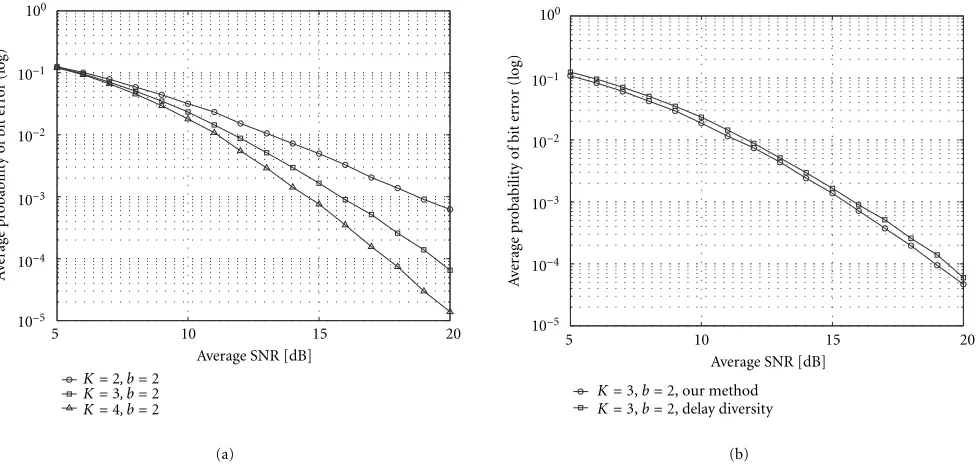
The repetition coded delay diversity of [10] is a special case of our design rules. Figure 5a shows the performance of this scheme for different number of transmit antennas (K =
2,3,4 andN=4,16,64, respectively) and QPSK modulation. We observe that the codes indeed provide different spatial diversity advantages since the steepness of the bit error rate curves is different.
The rest of the figures compare the performance of the delay diversity construction and our approach using the ex-ample codes described in the previous section. Figure 5b de-picts the results for three transmit antennas and QPSK mod-ulation. The two probability of bit error curves are shifted versions of each other, as expected. Approximately 0.4–0.5 dB coding gain is observed over the delay diversity scheme.
Figure 6a shows the bit error rate curves of a three trans-mit antenna system with 8PSK modulation. At low SNR, the two error performance curves are close to each other, and they behave according to the expectations at medium and high SNRs. This phenomenon can be explained as follows. The definition of coding advantage [9] is based on an upper bound on the Q(x) Gaussian tail probability function, and this bound is loose at low SNR. Moreover, the large number of transmission errors and the small minimum distance of the constellation may prevent the Viterbi algorithm with fi-nite decoding depth from working properly at low SNR. The simulation shows that the performance improvement is more pronounced; at higher SNR, more than 1 dB coding gain can be achieved.
The performance of the ST code for three antennas and 16PSK constellation can be observed in Figure 6b. Our ST code yields 2–2.5 dB coding gain compared to the delay di-versity scheme. Figures 7a and 7b depict the bit error rate curves for the four antenna ST codes using asymmetric QPSK and 4ASK modulation, respectively. The first figure shows approximately 3 dB coding gain from medium SNR, and the second figure demonstrates 2 dB improvement over the delay diversity construction.
5 10 15 20 10−5
10−4 10−3 10−2 10−1 100
K=2, b=2
K=3, b=2
K=4, b=2
Average SNR [dB]
A
ver
age
p
ro
babilit
y
o
f
b
it
er
ro
r
(log)
(a)
5 10 15 20
10−5 10−4 10−3 10−2 10−1 100
K=3,b=2, our method
K=3,b=2, delay diversity
A
ver
age
p
ro
babilit
y
o
f
b
it
er
ro
r
(log)
Average SNR [dB]
(b)
Figure5: Simulation results I. (a) Delay diversity with QPSK, (b) three transmit antennas with QPSK.
5 10 15 20
10−4 10−3 10−2 10−1 100
K=3,b=3, our method
K=3,b=3, delay diversity Average SNR [dB]
A
ver
age
p
ro
babilit
y
o
f
b
it
er
ro
r
(log)
(a)
10 11 12 13 14 15 16 17 18 19 20
10−3 10−2 10−1 100
K=3,b=4, our method
K=3,b=4, delay diversity Average SNR [dB]
A
ver
age
p
ro
babilit
y
o
f
b
it
er
ro
r
(log)
(b)
Figure6: Simulation results II. (a) Three transmit antennas with 8PSK, (b) three transmit antennas with 16PSK.
using ML sequence detection (Viterbi algorithm). Therefore, we chose a suboptimal tree decoding algorithm developed for convolutional coding and trellis coding: the M-algorithm [15]. This algorithm uses a tree structure to evaluate the met-rics (in our case: the Euclidean distances) for the allowable channel symbol sequences. At each stage, it keeps at mostM
partial paths with the best metrics. Thus, the decoding com-plexity isO(M), which is independent of the number of en-coder states.
Figure 8a shows the performance of the four antennas, QPSK ST code for ML decoding and for suboptimal decod-ing. The bit error curve of the three antennas, QPSK ST code with ML decoding is also included for comparison. It can be observed that reducing the computational
com-plexity (reducing the value of M) results in performance
degradation.
5 10 15 20 10−5
10−4 10−3 10−2 10−1 100
K=4, b=2, our method
K=4, b=2, delay diversity Average SNR [dB]
A
ver
age
p
ro
babilit
y
o
f
b
it
er
ro
r
(log)
(a)
5 10 15 20
10−5 10−4 10−3 10−2 10−1 100
K=4,b=2, our method
K=4,b=2, delay diversity Average SNR [dB]
A
ver
age
p
ro
babilit
y
o
f
b
it
er
ro
r
(log)
(b)
Figure7: Simulation results III. (a) Four transmit antennas with asymmetric QPSK, (b) four transmit antennas with 4ASK.
5 10 15 20
10−5 10−4 10−3 10−2 10−1 100
K=4, ML decoding
K=4, M-alg.,M=32
K=4, M-alg.,M=16
K=3, ML decoding
Average SNR [dB]
A
ver
age
p
ro
babilit
y
o
f
b
it
er
ro
r
(log)
(a)
5 10 15 20
10−7 10−6 10−5 10−4 10−3 10−2 10−1 100
K=2, ML decoding
K=4, ML decoding
K=6, M-alg.,M=256
K=8, M-alg.,M=256
K=10, M-alg.,M=256
Average SNR [dB]
A
ver
age
p
ro
babilit
y
o
f
b
it
er
ro
r
(log)
(b)
Figure8: Simulation results IV. (a) Four antennas, suboptimal decoding, (b) ST codes for QPSK modulation.
the ML decoding algorithm was used, and for the 6, 8, and 10 antenna cases, the ST codes were decoded by the subop-timal M-algorithm. The decoding complexity was kept ap-proximately constant by settingM=256. The used decoding depth values can be found in the last column of Table 3. The results show that as theN/Mratio increases, the performance loss increases.
7. CONCLUSION
Having observed the group/subgroup structure of the state transitions, we proposed systematic design rules for ST trellis codes that achieve full spatial diversity. For encoders having
Nmin states, we developed a code construction method that
coding advantage. Due to the low complexity of the proposed design method, ST codes for a large number of antennas were also constructed. Based on the theoretical coding advantage values and the simulation results, we can draw the following conclusions.
First, if the ratio of the maximum and the minimum dis-tances of the chosen constellation is large, the additional op-timization for coding advantage results in codes that substan-tially outperform the codes that were designed only for diver-sity advantage.
Second, if the M-algorithm is used to decode the ST codes with constant decoding complexity in a quasi-static Rayleigh fading environment, increasing the number of transmit an-tennas will provide diminishing returns. The choice of the number of transmit antennas will depend on the actual al-lowed maximum computational complexity.
APPENDIX
We will prove (12) by induction. Using (11), the first state change can be expressed easily
S1=B
Assume that the formula holds forSt−1, formally
St−1=Bt−1
It only remains to show that the above described relationship also holds forSt. Using the symbolQto denoteRBK+p−2,St
the state transition equation can be rewritten as
St=B
The next step is to make use of the following simple result: if
b∈ {0,1, . . . , B−1}then for any 0≤n < K+p−2
BnbmodRBK+p−2=Bnb. (A.8)
This allows for further simplification:
St=B
and we can obtain the following form:
St =B
REFERENCES
[1] S. Saunders, Antennas and Propagation for Wireless Commu-nication Systems, John Wiley & Sons, New York, NY, USA, 1999.
[2] S. Wicker, Error Control Systems for Digital Communication and Storage, Prentice Hall, Englewood Cliffs, NJ, USA, 1995.
[3] J. Winters, “On the capacity of radio communication systems with diversity in a Rayleigh fading environment,”IEEE Journal on Selected Areas in Communications, vol. 5, no. 5, pp. 871– 878, 1987.
[4] J. Winters, J. Salz, and R. Gitlin, “The impact of antenna di-versity on the capacity of wireless communication systems,”
IEEE Trans. Communications, vol. 42, no. 2-4, pp. 1740–1750, 1994.
[5] T. Marzetta and B. Hochwald, “Capacity of a mobile multiple-antenna communication link in Rayleigh flat fading,” IEEE Transactions on Information Theory, vol. 45, no. 1, pp. 139– 157, 1999.
[6] I. Telatar, “Capacity of multi-antenna Gaussian channels,” Technical report, AT&T Bell Labs., 1995.
[7] G. Foschini and M. Gans, “On the limits of wireless com-munication in a fading environment when using multiple an-tennas,” Wireless Personal Communication, vol. 6, no. 3, pp. 311–335, 1998.
[8] J.-C. Guey, M. Fitz, M. Bell, and W.-Y. Kuo, “Signal design for transmitter diversity wireless communication systems over Rayleigh fading channels,” inProc. IEEE Vehicular Technology Conference, vol. 1, pp. 136–140, Atlanta, Ga, USA, 1996. [9] V. Tarokh, N. Seshadri, and A. Calderbank, “Space-time codes
for high data rate wireless communication: performance cri-terion and code construction,”IEEE Transactions on Informa-tion Theory, vol. 44, no. 2, pp. 744–765, 1998.
[10] J. Grimm, M. Fitz, and J. Krogmeier, “Further results on space-time coding for Rayleigh fading,” inProc. 36th Aller-ton Conference on Communications, Control, and Computing, pp. 391–400, Monticello, Ill, USA, September 1998.
[11] A. R. Hammons, Jr. and H. El Gamal, “On the theory of space-time codes for PSK modulation,”IEEE Transactions on Infor-mation Theory, vol. 46, no. 2, pp. 524–542, 2000.
[12] R. Horn and C. Johnson, Matrix Analysis, Cambridge Uni-versity Press, UK, 1985.
[13] Q. Yan and R. Blum, “Optimum space-time convolutional codes,” Proc. IEEE Wireless Communications and Networking Conference, vol. 3, pp. 1351–1355, 2000.
[14] S. Baro, G. Bauch, and A. Hansmann, “Improved codes for space-time trellis coded modulation,” IEEE Communications Letters, vol. 4, no. 1, pp. 20–22, 2000.
[15] C. Schlegel,Trellis Coding, IEEE Press, 1997.
Zoltan Safar received the University
Diploma in electrical engineering from the Technical University of Budapest, Hungary in 1996. After one year of working experience, he started his graduate studies at the University of Maryland, where he is currently pursuing his Ph.D. in electrical engineering. His research interests include wireless communications and multimedia signal processing, with a particular focus on MIMO systems and space-time coding.
K. J. Ray Liureceived his B.S. degree from the National Taiwan University, and the Ph.D. degree from UCLA, both in electri-cal engineering. He is Professor of Electri-cal and Computer Engineering Department of the University of Maryland, College Park. His research interests span broad aspects of signal processing architectures; multimedia signal processing; wireless communications and networking; information security; and