Article
Generation and nonlinear frequency conversion of
nanosecond cylindrical vector beams in two-mode
fiber
Wending Zhang 1,*, Lu Zhang 1, Xin Li 1, Fanfan Lu 1, Chao Meng 1, Min Liu 1, Dexing Yang1, and
Ting Mei1
1 MOE Key Laboratory of Material Physics and Chemistry under Extraordinary Conditions and Shaanxi Key
Laboratory of Optical Information Technology, School of Science, Northwestern Polytechnical University, Xi’an 710072, China; E-Mails: [email protected] (L. Z.); [email protected] (X. L.); [email protected] (F. F. L.); [email protected] (C. M.); [email protected] (M. L.); [email protected] (D. X. Y.), [email protected] (T. M.).
* Correspondence: [email protected] (W. D. Z.); Tel.: +86-029-8843-1663.
Abstract: We present the generation and nonlinear frequency conversion of nanosecond cylindrical
vector beams (CVBs) in two-mode fiber (TMF). Based on the polarized dependence vector mode coupling characteristic and the precise wavelength tunability of an acoustically-induced fiber grating (AIFG), the nanosecond cylindrical vector beams (CVBs, 1064 nm, 10 ns) is directly generated in a TMF with convenient switching characteristics between the radial and azimuthal vector beams. Furthermore, the stimulated Raman scattering (SRS) is produced based on the transmission of the nanosecond CVBs in the 100-meters long TMF, and the spatial intensity and polarization distributions characteristics the 1st-order Stokes shifted component is consistent with
the nanosecond CVBs pump pulse. This work provides a method for achieving wavelength conversion of the CVBs in optical fiber.
Keywords: cylindrical vector beam, stimulated Raman scatting, Stokes shift.
1. Introduction
In recent years, the free space-based cylindrical vector beams (CVBs), as an important part of the light field regulation, have attracted extensive attention. Due to possessing polarization singularity distribution characteristic under condition of tight focusing, the CVBs have been extensively explored in many fields of the nonlinear effect enhancement [1], tip-enhanced Raman spectroscopy (TERS) [2-4], molecular orientation detection [5], dark-state excitation [6], micro/nano fabrication [7], optical tweezers [8], etc. In addition, it is noteworthy that the optical fiber-based CVBs would also open up various applications, such as optical fiber CVBs-based communication [9], fiber CVBs-based sensing [10], backgroundless plasmonic tip nanofocusing [11], quantum entanglement [12], stimulated emission depletion (STED) microscopy [13], surface enhanced Raman spectroscopy (SERS) [14], etc.
Up to now, the CVBs has been generated in optical fiber by using many methods, such as the mechanical micro-bend fiber grating [15], long-period fiber grating fabricated using CO2 laser [16],
fiber fused coupler [17], etc. However, those methods lack of precise wavelength tunability. In addition, the optical fiber is only used as a medium for conducting CVBs in these applications mentioned above. However, when the CVBs pulse transmits over long distances in an optical fiber, the nonlinear phenomena will appear due to the interaction between the CVBs pulse with extremely high peak power and the optical fiber [18, 19], although the nonlinearity effect of the fiber core is very weak. For instance, the stimulated Raman scattering (SRS) spectra up to 4th order Stokes shift
component has been experimentally observed in a 100-meters long hollow-core ring fiber pumped by a nanosecond pulse with radial polarization distribution [18], and the generated each order Stokes shift component also has radial polarization distribution characteristic. This nonlinear frequency
conversion process can create coherent radial vector beam (RVB) within a span of hundreds of nanometers. Nevertheless, it does not show the nonlinear transmission characteristic of the nanosecond pulse with linear polarization and azimuthal polarization distributions, since it’s difficult to in-situ switch linearly, radially and azimuthally polarized vector beams in optical fiber by using the mechanical micro-bend grating with fixed grating period.
In this paper, the nanosecond CVBs (1064 nm, 10 ns, 10 Hz) pulse is directly generated in a two-mode fiber (TMF) based on an acoustically-induced fiber grating (AIFG), and the generated nanosecond CVBs pulse has convenient switching characteristics between the radial and azimuthal vector beams. Furthermore, based on the long-distance transmission of the nanosecond CVB pulse in TMF, the stimulated Raman scatting (SRS) spectrum is experimentally observed. The spatial intensity and polarization distributions of the 1st-order Stokes shift component is consistent with the CVBs
pumped pulse.
2. Results and discussions
(a1) (a2) (a3) (a4) (a5) (a6) (a7)
(b)
(c) (d) (e)
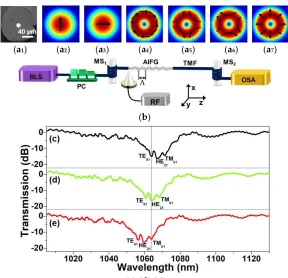
Figure 1. (a1) Optical microscope image of TMF; (a2) and (a3) Transverse mode intensity distributions
of the fundamental vector modes HEx
11 and HEy 11, respectively; (a4)-(a7) Transverse mode intensity
distributions of the first group high-order vector modes of TE01, HEe 21, HEo 21, and TM01, respectively; (b)
Experimental configuration for measuring the transmission spectra of the AIFG; (c-e) Wavelength tunability of the transmission spectra of the AIFG with three separated resonance peaks, corresponding to the coupling between HEx/y
11 modes and TE01, HEe/o 21, TM01 modes, respectively.
The optical microscope image of the TMF with core radius of 4.5 μm is shown in Fig. 1(a1). Figures
1(a2) and 1(a3) are the corresponding transverse mode intensity distributions of the fundamental
vector modes HEx
11 and HEy 11 at wavelength of 1064 nm, respectively. Figures 1(a4-a7) are the
transverse mode intensity distributions of the first group high-order vector modes of TE01, HEe/o 21, and
TM01, respectively. The transmission spectra of the AIFG constructed with TMF are used to examine
the high-order degenerate vector modes (TE01, HEe/o 21, TM01) separated characteristics [20, 21], and the
high-order vector modes (TE01, HEe/o 21, TM01) before the AIFG, a mode tripper (MS1) [22, 23], which is made
of 4 turns of TMF wound on a 10 mm diameter rod, is used to ensure a pure fundamental mode launching. The diameter of TMF for forming the AIFG is etched down to 28 μm by hydrofluoric (HF) acid to adjust the resonance wavelength based on the phase matching condition and to enhance the overlap between the acoustic and optical waves [24], thus increasing the acousto-optic coupling efficiency of the AIFG within the 10 cm long etched segment.
By tuning the voltage and frequency of the radio frequency (RF) driving signal applied to the acoustic transducer (AT), an AIFG is produced by the propagation of the linearly polarized acoustic flexural wave along the unjacketed TMF [25]. When the BLS transmits along the acousto-optic interaction region of the AIFG, the fundamental vector mode (HEx/y
11) can be coupled to the first-group
of high-order vector modes (TE01, HEe/o 21, TM01) with the phase-matching condition LB= to be satisfied,
where LB=λ/Δneff is the beat length between HEx/y 11 modes and TE01, HEe/o 21, TM01 modes, and is the
grating period of the AIFG [26, 27]. At the output terminal of the TMF, the other mode stripper (MS2),
is also made with parameter same as MS1 to filter out the generated high-order vector modes, and
leave only the fundamental vector mode in the core of TMF. The output spectra are measured by using an optical spectrum analyzer (OSA AQ6370D). Figures 1(c-e) are the wavelength tunability of the transmission spectra of the AIFG when three RF driving signals, with frequencies of 1.331 MHz, 1.346 MHz, and 1.360 MHz, are applied to the AT, respectively. Note that the resonance wavelength shifts toward short wavelength with increasing the frequency of the RF driving signal. It's noteworthy that the transmission spectrum of the AIFG has three separated resonance peaks with central wavelength interval of ~3.8 nm, which indicates that the high-order degenerate vector modes (TE01, HEe/o 21 and TM01) have been effectively separated in TMF [20], and the three separated resonance
peaks are corresponding to the coupling between the fundamental vector modes (HEx/y
11) and the
high-order vector modes of TE01, HEe/o 21, and TM01, respectively.
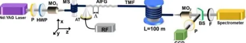
The experimental configuration for generating the nanosecond CVBs in TMF based on the AIFG is shown in Fig. 2. At the input terminal, the BLS is replaced by a 1064 nm Q-switched Nd: YAG laser (Dawa 100), with pulse width and repetition frequency of 10 ns and 10 Hz, respectively. The nanosecond pulse is linearly polarized by a linear polarizer (P), and then the polarization orientation is adjusted by a half-wave plate (HWP). An average power of 42 mW is measured for the nanosecond pulse before injecting into TMF via a micro-objective (MO1 40x, 0.65). The mode stripper (MS) is used
to purify the laser beam to be the linearly-polarized fundamental vector mode, by filtering out the high-order vector modes through critical bending loss [22]. When the linearly-polarized fundamental mode (HEx
11 or HEy 11) propagates along the acousto-optic interaction region of the AIFG induced via
the linearly-polarized acoustic flexural wave with polarization direction paralleling to the x-axis.
Based on the polarized dependence vector mode coupling characteristic of the AIFG [21], the HEx
11
and HEy
11 modes can be respectively coupled to TM01 and TE01 modes with phase-matching condition
to be satisfied [23], simultaneously. The generated CVBs (TM01, TE01) transmits in TMF for a length of L=100 m, and then outputs from the end of TMF after collimating via a 40× micro-objective (MO2).
The CVBs outputting from MO2 is reflected by a beam splitter (BS) and then captured by a charged
coupled device (CCD). In addition, a polarizer (P) is inserted between BS and CCD to examine the polarization distribution characteristic of the CVBs by rotating P. Meanwhile, the transmitted CVBs via BS is coupled into a spectrometer (Andor SR-500i-B1-R-1F1) to examine the lasing spectrum of the nanosecond CVBs pulse.
Figure 3(a) is the typical pulse train of the nanosecond Gaussian pulse with repetition frequency of 10 Hz, and the inset is the temporal width rising edge of ~10 ns. The corresponding lasing spectrum of the nanosecond Gaussian pulse, with central wavelength and bandwidth of 1064.2 nm and 4.7 nm, is shown as the black curve in Fig. 3(b). The blue curve in Fig. 3(b) is the transmission spectrum of the AIFG with three separated resonance peaks, when an RF driving signal with frequency of f=1.346 MHz is applied to the AT. The three resonance peaks with central wavelength interval of ~3.8 nm is corresponding to the vector mode coupling of TE01, HE21, and TM01 as the resonance wavelength
increases. Note that the bandwidth and central wavelength of the resonance peak of HE21 is coincided
with the lasing spectrum of the nanosecond pulse. Thus, when the nanosecond pulse is coupled into TMF and propagates along the acousto-optic coupling region of the AIFG (Fig. 2), the HE11 mode of
the lasing spectrum could be almost completely converted to HE21 mode through AIFG. Similarly,
the resonance wavelength of the AIFG can be adjusted to make the resonance peak corresponding to TM01 mode coincide with the lasing spectrum, as shown in Fig. 3(c), when the frequency of RF driving
signal is adjusted to 1.360 MHz. The HEx
11 mode can be coupled to TM01 mode with radial polarization
distribution via the AIFG. Moreover, TE01 mode with azimuthal polarized distribution can also be
generated, as shown in Fig. 3(d), when the input fundament mode is changed as HEy
11 and the central
wavelength and bandwidth of the resonance peak corresponding to TE01 mode is adjusted to coincide
the lasing spectrum by using RF frequency of 1.331 MHz.
(a) (b)
(c) (d)
Figure 3 (a) Typical pulse train of the nanosecond pulse with repetition frequency of 10 Hz, and inset is the temporal width of nanosecond pulse with rising edge of ~10 ns; Transmission spectra of the AIFG (blue curves) with three separated resonance peaks corresponding to the coupling between HE11
mode and HE21 (b), TM01 (c), TE01 (d) to coincide with the lasing spectrum (black curves) of the
nanosecond pulse with central wavelength of 1064 nm.
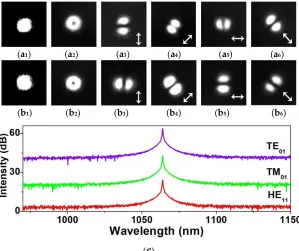
When the RF driving signal is turned off, the transverse mode intensity pattern of HEx 11 mode
output from TMF is shown in Fig. 4(a1). In order to generate the nanosecond radial vector beam
(TM01), the frequency of RF driving signal is set as 1.360 MHz to produce an AIFG with the resonance
peak of TM01 coincided with the lasering spectrum, as shown in Fig. 3(c). Thus, the HEx 11 mode is
azimuthal vector beam (TE01), the HEx 11 is changed as HEy 11 via the HWP, and then the RF frequency
is set as 1.331 MHz to produce an AIFG with the resonance peak of TE01 coincided with the lasering
spectrum, as shown in Fig. 3(d), the HEy
11 mode can be coupled to TE01 mode via the AIFG, as shown
in Fig. 4(b2). A polarizer (P) is inserted between the CCD and the BS to examine the polarization
distribution characteristic of the nanosecond CVBs. The intensity patterns at various polarizations are shown in Figs. 4(a3-a6) and 4(b3-b6), respectively. In addition, the lasing spectra of the nanosecond
pulse with transverse mode intensity distributions of HE11, TM01, and TE01 are shown as the red, green
and violet curves in Fig. 4(c), respectively. Note that the spectral bandwidth and shape of the nanosecond pulse with three transverse mode intensity distribution remains essentially unchanged.
(a1) (a2) (a3) (a4) (a5) (a6)
(b1) (b2) (b3) (b4) (b5) (b6)
(
c
)Figure 4 (a1) and (b1) Modes intensity distributions of HEx 11 and HEy 11 modes, respectively; (a2) and (b2)
Modes intensity distributions of TM01 and TE01 modes, respectively; Mode intensity distribution of
TM01 (a3-a6) and TE01 (b3-b6) modes in presence of P at different polarization orientations. (c) Lasing
spectra of the nanosecond pulse with transverse mode intensity distributions of HEx/y
11, TM01 and TE01
modes.
Furthermore, the nonlinear transmission characteristic of the nanosecond pulse, with transverse modal intensity distributions of Gaussian (HE11), radial (TM01) and azimuthal (TE01), are
experimentally observed in a 100-meters long TMF. With increase of the pump power of the nanosecond pulse with Gaussian distribution (HE11), the 1st-order Stokes shift component appears
and gradually increase, as shown in Fig. 5(a), and the relationship between the pump power and the intensity of the 1st-order Stokes shift component is also shown as the inset in Fig. 5(a). Note that the
central wavelength of the 1st-order Stokes shift component is ~1116.8 nm with a frequency shift of
~13.2 THz (440 cm-1) relative to the central wavelength of the pump pulse, and it’s corresponding to
the peak of the broad Raman band of the fused silica (SiO2) [18]. In addition, the intensity of the 1st
-order Stokes shift component reaches the maximum with an average pump power of P=1.05 mW, but
the 1st-order Stokes shift component is not saturated under condition of the average pump power of
P=1.05 mW, because further increase of the pump power will damage the end face of TMF in the case
(a) (b) Figure 5. (a) SRS spectra pumped by using the nanosecond pulse with HEx
11 mode, when the average
pumped power is set as P=0.66 mw, 0.76 mw, 0.85 mw, 0.95 mw, 1.05 mw, respectively. Inset is the relationship between the pump power and the intensity of the 1st-order Stokes shift component; (b)
SRS spectra pumped via the nanosecond pulse with HEx
11 (pink curve) and TM01/TE01 (green curve)
modes, respectively.
The SRS spectra of the 100-meters long TMF pumped by the nanosecond pulse with Gaussian and radial (TM01) polarization distributions, are shown as the pink and green curves in Fig. 5(b),
respectively, under condition of P=1.05 mW. Note that the intensity of the 1st-order Stokes shift
component pumped via the radial vector mode (TM01) decreases by five times compared with the
Gaussian mode pump. The main reason is that the radial vector mode (TM01) with annular intensity
distribution reduces the power density of the pump pulse.
Figure 6(a1) and 6(a2) are the transverse mode intensity distributions of the 1st order stokes shift
component pumped via the nanosecond pulse with radial (TM01) and azimuthal (TE01) polarization
distribution, respectively. By inserting and rotating a polarizer between CCD and BS, the polarization distribution characteristic of Figs. 6(a1) and 6(a2) can be examined and the examination results are
shown as Figs. 6(a2-a5) and 6(b2-b5), revealing the Figs. 6(a1) and 6(a2) with radial and azimuthal
polarization distribution characteristics, respectively.
(a1) (a2) (a3) (a4) (a5)
(b1) (b2) (b3) (b4) (b5)
Figure 6. (a1) and (b1) Modes intensity distributions of TM01 and TE01 modes of the 1st-order Stokes
shift component of SRS spectrum, respectively; Polarization distribution examinations of TM01 (a2-a5)
3. Conclusions
In summary, we have presented the generation and nonlinear frequency conversion of the nanosecond CVBs pulse (10 ns, 1064 nm) in a 100 meters-long TMF. Based on the polarized dependence vector mode coupling characteristic of the AIFG and the degenerate vector mode effective separation of TMF, the nanosecond CVBs pulse has been directly generated in TMF via AIFG. By using the long-distance transmission of the nanosecond CVBs pulse in TMF, the SRS spectrum is excited and the 1st-order Stokes shift component has the same spatial intensity and
polarization distributions as the CVBs pumped pulse. This work provides a method for achieving wavelength conversion of the CVBs in optical fiber.
Author Contributions: W.D.Z proposed the original idea and defined research topic; X.L., L.Z. and C.M. carried out the experiments; F.F.L. and M.L. helped with experiments and analysis. D.X.Y and T.M help with analysis and discussion. All authors contributed to the discussion of the results as well as to the preparation and writing of the manuscript.
Funding: This work was financially supported the Natural Science Foundation of China (NSFC) (61675169, 61675171), and the Natural Science Basic Research Plan in Shaanxi Province of China (2018JM6036).
Conflicts of Interest: The authors declare no conflict of interest.
References
1. Wang, X. H.; Shen, S.; Sun, J. W.; Fan, F.; Chang, S. J., Surface and bulk second-harmonic responses from a glass slide using tightly focused radially polarized light. Opt. Lett. 2016, 41, 5652-5655. 10.1364/OL.41.005652.
2. Hayazawa, N.; Saito, Y.; Kawata, S., Detection and characterization of longitudinal field for tip-enhanced Raman spectroscopy. Appl. Phys. Lett. 2004, 85, 6239. 10.1063/1.1839646.
3. Zhang, M.; Wang, J.; Tian, Q., Tip-enhanced Raman spectroscopy mapping with strong longitudinal field excitation. Opt. Commun. 2014, 315, 164–167. 10.1016/j.optcom.2013.10.069.
4. Saito, Y.; Verma, P., Polarization-controlled Raman microscopy and nanoscopy. Phys. Chem. Lett.2012, 3, 1295−1300. 10.1021/jz300213t.
5. Mino, T.; Saito, Y.; Yoshida, H.; Kawata, S.; Verma, P., Molecular orientation analysis of organic thin films by z-polarization Raman microscope. J. Raman Spectrosc.2012, 43, 2029–2034. 10.1002/jrs.4118.
6. Sancho-Parramon, J.; Bosch, S., Dark modes and Fano resonances in plasmonic clusters excited by cylindrical vector beams. ACS Nano 2012, 6, 8415-8423. 10.1021/nn303243p.
7. Skoulas, E.; Manousaki, A.; Fotakis, C.; Stratakis, E., Biomimetic surface structuring using cylindrical vector femtosecond laser beams. Sci. Rep. 2017, 7, 45114. 10.1038/srep45114.
8. Furst, E. M.; Gast, A. P., Micromechanics of dipolar chains using optical tweezers. Phys. Rev. Lett. 1999, 82, 4130–4133. 10.1103/PhysRevLett.82.4130.
9. Liu, J.; Li, S. M.; Zhu, L.; Wang, A. D.; Chen, S.; Klitis, C.; Du, C.; Mo, Q.; Sorel, M.; Y. Yu, S.; Cai, X. L.; Wang, J., Direct fiber vector eigenmode multiplexing transmission seeded by integrated optical vortex emitters. Light: Sci. & Appl. 2018, 7, 17148. 10.1038/lsa.2017.148.
10. Demas, J.; Alkeskjold, M. D. W. T.; Ramachandran, S., Sensing with optical vortices in photonic-crystal fibers. Opt. Lett.2012, 37, 3768-3770. 10.1364/OL.37.003768.
11. Liu, M.; Lu, F. F.; Zhang, W. D.; Huang, L. G.; Liang, S. H.; Mao, D.; Gao, F.; Mei,T.; Zhao, J. L., Highly efficient plasmonic nanofocusing on a metallized fiber tip with internal illumination of the radial vector mode using an acousto-optic coupling approach. Nanophotonics2019, 10.1515/nanoph-2019-0027.
12. Ramachandran, S.; Kristensen, P., Optical vortices in fiber. Nanophotonics2013, 2, 455-474. 10.1515/nanoph-2013-0047.
13. Gu, M.; Kang, H.; Li, X. P., Breaking the diffraction-limited resolution barrier in fiber-optical two-photon fluorescence endoscopy by an azimuthally-polarized beam. Sci. Rep.2014, 4, 3627. 10.1038/srep03627. 14. Liu, M.; Zhang, W. D.; Lu, F. F.; Xue, T. Y.; Li, X.; Zhang, L.; Mao, D.; Huang, L. G.; Gao, F.; Mei,T.; Zhao,
J. L., Plasmonic tip internally excited via azimuthal vector beam for surface enhanced Raman spectroscopy.
Photonics Res. 2019, 7, 526-531. 10.1364/PRJ.7.000526.
16. Li, S. H.; Mo, Q.; Hu, X.; Du, C.; Wang, J., Controllable all-fiber orbital angular momentum mode converter.
Opt. Lett.2015, 40, 4376-4379. 10.1364/OL.40.004376.
17. Pidishety, S.; Srinivasan, B.; Brambilla, G., All-fiber fused coupler for stable generation of radially and azimuthally polarized beams. IEEE Photon. Technol. Lett.2017, 29, 31-34. 10.1109/LPT.2016.2625421 18. Ramachandran, S.; Smith, C.; Kristensen, P.; Balling, P., Nonlinear generation of broadband polarisation
vortices. Opt. Express2010, 18, 23212-23217.10.1364/OE.18.023212.
19. Rishøj, L.; Kristensen, P.; Ramachandran, S.; Rottwitt, K., Experimental demonstration of intermodal nonlinear effects between full vectorial modes in a few mode fiber. Opt. Express 2013, 21, 28836-28841. 10.1364/OE.21.028836.
20. Zhang, W. D.; Li, X.; Zhang, L.; Lu, F. F.; Huang, L. G.; Gao, F., Generation of cylindrical vector beams and optical vortex in a solid-core ring fiber based on an acoustically-induced fiber grating. IEEE Journal of Selected Topics in Quantum Electronics2019, 10.1109/JSTQE.2019.2906274.
21. Zhang, W. D.; Huang, L. G.; Wei, K. Y.; Li, P.; Jiang, B. Q.; Mao, D.; Gao, F.; Mei, T.; Zhang, G. Q.; Zhao, J. L., Cylindrical vector beam generation in fiber with mode selectivity and wavelength tunability over broadband by acoustic flexural wave. Opt. Express2016, 24, 10376-10384. 10.1364/OE.24.010376.
22. Wei, K. Y.; Zhang, W. D.; Huang, L. G.; Mao, D.; Gao, F.; Mei, T.; Zhao, J. L., Generation of cylindrical vector beams and optical vortex by two acoustically induced fiber gratings with orthogonal vibration directions.
Opt. Express 2017, 25, 2733-2741. 10.1364/OE.25.002733.
23. Zhang, X. C.; Zhang, W. D.; Li, C. Y.; Mao, D.; Gao, F.; Huang, L. G.; Yang, D. X.; Mei, T.; Zhao, J. L., All-fiber cylindrical vector beams laser based on an acoustically-induced All-fiber grating. J. Opt.2018, 20, 075608. 10.1088/2040-8986/aaca1c.
24. Dashti, P. Z.; Alhassen, F.; Lee, H. P., Observation of orbital angular momentum transfer between acoustic and optical vortices in optical fiber. Phys. Rev. Lett.2006, 96, 043604. 10.1103/PhysRevLett.96.043604. 25. Zhang, W. D.; Wei, K. Y.; Huang, L. G.; Mao, D.; Jiang, B. Q.; Gao, F.; Zhang, G. Q.; Mei, T.; Zhao, J. L,
Optical vortex generation with wavelength tunability based on an acoustically-induced fiber grating. Opt. Express2016, 24, 19278-19285. 10.1364/OE.24.019278.
26. Zhang, W. D.; Huang, L. G.; Wei, K. Y.; L, P.; Jiang, B. Q.; Mao, D; Gao, F.; Mei, T.; Zhang, G. Q.; Zhao, J. L., High-order optical vortex generation in a few-mode fiber via cascaded acoustically driven vector mode conversion. Opt. Lett.2016, 41, 5082-5085. 10.1364/OL.41.005082.