Experimental investigation of an aggregate material behavior
under confinement at high strain rate
J. Vial1, 2, P. Bailly2, F. Delvare2,a, M. Biessy1 and D. Picart1
1
CEA, DAM, Le Ripault, F-37260 Monts, France 2
Institut PRISME, ENSI de Bourges, 88 Boulevard Lahitolle, 18020 Bourges Cedex, France
Abstract. Low velocity impacts can ignite explosives or energetic materials. Ignition depends on the mechanical behavior of the energetic material which needs to be characterized for both high pressure level and high strain rate. A technique based on the Split Hopkinson Pressure Bars system is proposed to reproduce these loading conditions. A cylindrical specimen is placed in a confining ring and is dynamically compressed. The ring prevents the radial extension and confines the specimen. Each ring is designed to plastify and to obtain a constant radial pressure during the test. Some experiments are carried out on an inert aggregate material and show the validity of this experimental device.
1 Introduction
The use of explosives for industrial purposes or military applications is widely spread. Requirements for these materials are energetic performances and safety. However, it was shown that some explosive compositions reacted violently when submitted to a low velocity impact (the pressure is far from the shock to detonation transition threshold) [1]. The mechanical behavior of the explosive is one of the keys needed to predict such an event [2-3].
The aim of this study is to set up an experiment to observe the behavior of energetic materials in terms of both high strain rate and high pressure, in the closest loading conditions corresponding to low velocity impacts.
The original experimental device we propose here submits a representative specimen to a dynamic compression and a lateral confinement. The traditional Split Hopkinson Pressure Bars (SHPB) system is combined with a confining ring to reach a strain rate of 1000 s-1 and a confining pressure of 500 MPa.
For safety reasons, a simulant inert material I1 is used. I1 is an aggregate composite manufactured by hot hydrostatic press moulding. It is composed of crystals of barium meal (BaSO4), of melamine and of a binder. I1 has a mean density of 1.73 with a high residual porosity of 28 %. In the next sections of this paper, the proposed dynamic triaxial test as well as a typical experimental data processing are detailed.
a e-mail : [email protected] © Owned by the authors, published by EDP Sciences, 2010 DOI:10.1051/epjconf/20100639006
2 The dynamic triaxial test
Experimental impact tests and numerical studies [3] have clarified the loading conditions during low velocity impact. The pressure can reach 300 to 500 MPa when a strain rate equal to 104 s-1 is expected, as well as finite strains approaching 1.
It has been shown that the behavior of this material is dependent on both the pressure and the strain rate [4]. Thus it is necessary to design a test imposing a sliding plastic strain of the material I1 with both a constant confining pressure and an almost constant strain rate. As high strain rates are hardly tractable, we restrict our study to 1000 s-1.
2.1. Brief description of the SHPB system
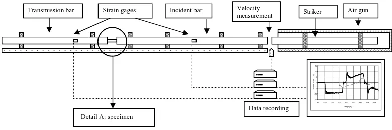
The SHPB system is now commonly used to characterize materials at high strain rates. In our set-up, the specimen is axially loaded using the SHPB system (Figure 1). The system is composed of an input bar and an output bar. The specimen is placed between them. When the striker shocks the input bar at its free end, a compressive longitudinal incident wave is generated. Once this incident wave reaches the interface between the specimen and the bar, a reflected pulse appears in the input bar as well as a transmitted one in the sample (which itself produces a transmitted wave in the output bar). Strain gauges are glued on the input and the output bars. It allows to record the three basic waves (input and reflected waves in the input bar and transmitted wave in the output bar). The bars, made of steel (the elastic yield is 1000 MPa), have a 20 mm diameter, while the input bar is 3 m long. At last, the output bar is 2 m long. The striker is 1.2 m long. The length of the striker and the strain gauges positions allow a test duration of about 400 µs.
Fig. 1: Classical SHPB system
Between the bars, a cylindrical specimen is placed (the diameter and the height are equal to 10 mm). The specimen being surrounded by a metallic ring, lateral expansion is limited during the axial compression applied by the bars. The consequence is an increase in the confining pressure.
-15 -10 -5 0 5 10 15
800 10001200 1400 16001800 2000 22002400 Temps (µs)
"D
é
fo
rm
a
ti
on
"
(V
)
Transmission bar Strain gages Incident bar Velocity Striker Air gun measurement
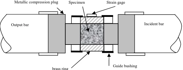
Fig. 2: The confining system (detail A: figure 1)
2.2. Determination of the axial stress
Data processing of the waves is done using the DAVID software, which includes a wave dispersion correction and an assisted time shifting based on the elastic transient response of the specimen [5-7]. The relations that give the velocities (Vinput and Voutput) at both ends of the specimen are:
( )
t C( )
tVoutput = Bεt
( )
t C[
( ) ( )
t t]
Vinput = B εi −εr
where CB is the wave’s celerity in the bars, εi, εr and εt are respectively the incident, the reflected and the
transmitted strains of the corresponding waves. The relations which give the forces at both ends of the specimen are:
( )
t S E( )
tFoutput = B Bεt
( )
t S E[
( ) ( )
t t]
Finput = B B εi +εr
where SB is the section and EB is the Young modulus of the steel bars.
With the assumption of homogeneity of the stresses and of the strains in the specimen, the mean axial strain and the mean strain rate are given by the following relations:
( )
[
U( )
t U( )
t]
L1
t output input
axial = −
ε
( )
∫
( )
τ τ = t 0 inputinputt V d
U
( )
[
V( )
t V( )
t]
L1
t output input
axial = −
ε&
with L the specimen length.
The axial stress can be estimated by using the force measured by the output bar or by using the mean of both forces measured by the output and the input bars:
( )
F( )
tS 1 t output s axial = σ
( )
[
F( )
t F( )
t]
S 2
1
t input output
m
axial = +
σ
where S is the specimen section.
The axial stress homogeneity is obtained when the two boundary forces are identical. A stress-strain Strain gage Specimen brass ring Incident bar Output bar Guide bushing Metallic compression plug
2.3. Confinement using an elastoplastic ring
To carry out our dynamic triaxial tests, two main difficulties must be solved. The first one is to keep a constant confining pressure during a useful part of the test whereas the second is to reach the highest possible amplitude (≈ 200 MPa).
To obtain a constant confining pressure, it is possible to use a cell with compressed air or liquid [8-9]. However, this technique does not achieve the desired high confinement. Higher values of the pressure can be obtained by placing the specimen in a steel ring to achieve a passive confinement. This technique has been used in quasi-static tests [10-13] or in dynamic experiments [14-17]. The elastic behavior of the steel ring allows to deduce the pressure on the inner wall from the measurement of the strains on the outer wall of the steel ring. In these tests, the radial strains are neglected compared to the axial strain. These experiments are considered as quasi-oedometric ones.
This technique is not directly transposable for us for three reasons: - a constant confining pressure cannot be ensured,
- the sliding plastic strains observed are too low or negligible, - the shear fracture does not necessarily occur.
For a loading that approximates that of a conventional triaxial test, the idea is to have a confining ring completely plastified during the last phase of the test. If a perfectly plastic material is used for the ring, the transverse stress remains constant. This stress is the confining pressure Pc and the corresponding loading path is parallel to the one of the uniaxial compression in the pressure-deviatoric plane.
2.4. Determination of the confining pressure
The analysis of the test requires a perfect knowledge of the elasto-plastic behavior of the ring material. The proposed material is brass. It has an elasto-plastic behavior without strain rate dependence. In order to obtain several values of the confinement pressure, rings with different thicknesses can be used.
The determination of the created lateral confining stress is deduced from an analytical model of the ring. The parameters that influence this model are:
- the height of the ring (which is equal to the length of the specimen), - the friction between the specimen and the ring,
- the behavior of the ring material.
Where the ring and the specimen have the same length, and if the friction is neglected, the case of an elastic ring can be considered in a plane stress state similar to that described in the Lamé’s cell method. If the ring is longer than the specimen, the Lamé solution is a rough estimate [18].
In the situation described here, during the relevant phase of the test, the ring which carries the passive confinement is plastified. If the Tresca criterion is used, this problem has an analytical solution assuming a perfect elastoplastic behavior of the material and a plastic incompressibility. The solution expression varies with the state of the ring:
- if the ring is elastic
2 2 2 1 R R e m ε
ε <
(
2)
1 2 1 2 2 2 -R R R E m lateral ε σ =
- if the ring is partially plastic
e m e R R ε ε
ε 2 < <
2 2
1
(
)
- if the ring is totally plastified
m e ε
ε < = ln
1 2
R R
e lateral σ σ
where R1 and R2 are respectively the inner and outer diameter of the ring, εm is the measured strain, E is the Young modulus, σe is the elastic yield stress of the ring and εe is the elastic yield strain of the ring.
3. Typical experimental data processing
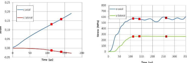
Data processing is presented here for a test with a confining ring with an outer diameter of 20 mm. The data are the strains measured on the input and on the output bars and by the gauge (circumferentially oriented) located on the confining ring (figure 3). The axial and lateral strains and stresses versus time are given in figure 4.
Fig. 3: Raw electrical signals recorded by the different gauges.
Fig. 4: Evolutions of the axial strain (or stress) and the lateral strain (or stress) versus time.
Three specific points are represented in figure 4 (two on the graph corresponding to strains): - The first point corresponds to the moment when the ring is plastified. From that moment, the test is close to a conventional triaxial test.
- The second point is the end of the reliable measurement of the radial strain (corresponding to the deformation limit of the gauge glued on the ring).
- The last one corresponds to the final stress state (maximum axial stress).
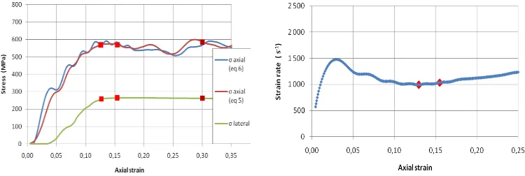
equality of σ1S and σ1m is not checked before the point 1. Therefore, only the useful part may be used to study the behavior of the material. The second part of figure 5 gives the axial strain rate.
Fig. 5: Evolution of the stresses and the axial strain rate versus the axial strain.
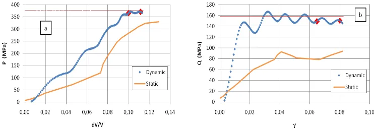
During the useful phase of the test, the strain rate is almost constant. Results can be compared with those obtained during a quasi-static test using the same ring. Figure 6a shows the loading paths in the pressure-deviatoric stress diagram. Pressure P is given by:
σ trace P=31
and Q is the octahedral stress defined by:
S : S Q= 31
I P S=σ
-Figure 6b shows the loading paths in the γ-dV/V diagram where dV/V denotes the volumetric strain defined by:
(
1 2)
3 1 ε +2ε =
V / dV
and γ denotes the distortion strain defined by:
(
1 2)
23 ε -ε γ =
where ε1 and ε2 are respectively the longitudinal and the transversal strains.
Figure 7 shows the hydrostatic (a) and the deviatoric behaviors (b) of the material.
Fig. 6: Loading paths in terms of stresses (a) and of strains (b).
(10)
(11)
(12)
Fig. 7: Hydrostatic (a) and deviatoric behaviors (b) of the material.
During the useful phase of the test, the pressure is constant (figure 7a) and a significant sliding plastic strain is produced (figure 7b).
4. Discussion of the results
In terms of ring deformation, the assumption of a plane problem is checked. The axisymmetry is preserved after the test and the plastic strain has only increased the diameter of the ring while the height remained unchanged. In this case, the analytical solution seems acceptable.
Because the specimen has the same height as the ring, the configuration requires the use of guide bushings to ensure a coaxial compression of the specimen (figure 2). Several identical tests were made in order to check the reproducibility of the procedure.
Friction between the ring and the material is negligible. Some tests were made with shorter rings (height equal to 5 mm). No effects were noticed. Given the precision of the measurement of the axial stress (5 %), in order to have an effective lateral friction, it is necessary that the friction force exceeds 10 % of the axial force. A rough estimate of this force can be made by assuming a uniform distribution of the shear stresses at the interface. The friction force would have had a detectable effect on the axial stress value if the friction coefficient were higher than 0.1, which was not the case here.
Many tests were made with different outer diameters of the ring in order to obtain various confining pressure. The results prove that the coupling between a high pressure and a high strain rate has a great influence on shear stress and thus on the dissipated energy.
5. Conclusion
The study of explosive materials requires experimental data coupling a high pressure to a high strain rate. A dynamic triaxial test has been proposed. During the phase development and for safety reasons, the tested material was an inert simulant of the explosive. This material is embedded into a metallic ring, and submitted to a dynamic compression. It allows to reproduce impact conditions with pressures up to 300 MPa, strain rates of about 1000 s-1 and significant sliding plastic strains.
Throughout the test, the cylindrical symmetry has been kept allowing uniform stresses and strains into the specimen. It also allows the processing of data and the determination of the radial stress from the analytical solution which takes into account the perfect elasto-plastic behavior of the ring.
The experimental results will be used in future works to propose and to identify models for the dynamic behavior of frictional and cohesive materials.
References
[1] Idar D, Straight J, Osborn M, Coulter W, Skidmore C, Phillips D, DeCroix M, Buntain G, Howess P. Los Alamos Sci. report LA-UR-00-5334, (2000)
[2] Browning RV, Scammon RJ. Shock Compres. Condens. Matter, CP620, 987-990, (2001)
[3] Gruau C, Picart D, Belmas R, Bouton E, Delmaire-Sizes F, Sabatier J, Trumel H. Int J Impact Eng, 36, 537-550, (2009)
[4] Le VD, Thesis Université de Tours, (2007)
[5] Gary G, Klepaczko JR, Zhao H, Proc. of Int. Symp. Impact Eng., 1, 73–78, (1992) [6] Gary G, DAVID, instructions manual, (2005)
[7] Zhao H, Gary G, Int J Solids Struct, 33, 3363-3375,(1996)
[8] Semblat JF, Gary G, Luong MP, Proc. IS-TOKYO'95 First Int. Conf. Earthquake Geotechnical Eng. Tokyo, (1995).
[9] Gary G, Bailly P, Eur. J. of Mech.-A/Solids, 17(3), 403-420, (1998)
[10] Bažant ZP, Bishop FC, Chang TP, J. Am. Conc. Inst., 83(4), 553–560, (1986)
[11] Burlion N, Pijaudier-Cabot G, Dahan N, Int. J. Num. Anal. Methods in Geomech, 25, 15, 1467– 1486, (2001)
[12] Forquin P, Arias A, Zaera R, Int J Solids Struct,44, 13, 4291–4317,(2007) [13] Gabet T, Malécot Y, Daudeville L, Cem. Conc. Res., 38, 3, 403–412, (2008), [14] Christensen RJ, Swansow SR, Brown WS, Exp Mech, 12, 11, 508-541, (1972)
[15] Malvern LE, Jenkinds DA, Tang T, Mc Lure S, Micromech. Fail. quasi brittle mat., 343-352,(1991) [16] Gary G, Bailly P, Gatuingt F, 3th Int. Symp. on Impact Engineering’98, Singapore, (1998).