Parametric Evaluation of Outrigger Structural System
for High Rise Buildings
DEEPTHI M UMASHANKAR PATIL G H
PG Student, Department of Civil Assistant Professor, Department of Civil Nitte Meenakshi Institute of technology Nitte Meenakshi Institute of technology
Yelahanka, Bengaluru, India Yelahanka, Bengaluru, India Email: [email protected] Email: [email protected]
ABSTRACT
Construction of tall buildings has been increasing rapidly all over the world. Tall buildings are majorly induced by the lateral forces like wind and seismic loads. In tall buildings stiffness parameter plays a major role. When the building height increases, the stiffness decreases. To control the effect of lateral loads acting on the structure and to increase the stiffness, lateral load resisting system will be introduced. The introduction of outrigger system can be used in order to achieve reduction in the drift and deflection due to the lateral load. In the present study, the seismic behavior of different structural configuration of the outrigger structural system has been studied. The analysis is done by considering a 30 storey building of regular steel structure and is modeled by using ETABS version 9. Parametric evaluation of outrigger structural system with varied structural configuration is performed for zone V to check the variation in response for Equivalent Static Analysis and Response Spectrum Analysis. The objective of this paper is to study the behavior of the outriggers and to choose the appropriate system among the different outrigger structural system. The structural response parameters like base shear, lateral displacement, storey drift and time period are compared. The structural efficiency of each system is studied depending on different configuration adopted based on the considered parameters.
Keywords- Outrigger structural system, Stiffness, Displacement, Drift, Time Period, Base Shear, Lateral Load Resisting System.
I. INTRODUCTION
Tall buildings have to be designed by considering the factors while selecting the structural system for buildings. Lateral loads are usually induced by the wind or earthquake in modern tall buildings which are often resisted by the required structural system. As the building height increases stiffness parameter becomes more important. To provide sufficient lateral stiffness to the structure, lateral load resisting system is used. By providing the lateral load resisting system, the excessive drift due to lateral load can be controlled effectively even during small or medium lateral load. The risk of structural and non-structural damage can be minimized by providing the structural systems.
B. Outrigger Structural System for High Rise Building
In outrigger structural system the external columns lying on the periphery of the structure are tied with belt truss and the outriggers connect these belt trusses to the central core of the structure, due to this arrangement the exterior columns are restrained from rotation. The space between the central core and the exterior columns is a free floor space so this system proves to be functionally efficient.
Under lateral loading, Outrigger structural system makes the structural form very efficient by increasing the stiffness of the structure. Outrigger system eventually reduces the overturning moment inducing on the core due to lateral loads and further by the action of tension-compression coupled, it transfer the reduced moment to columns outside the core, which take advantage of the increase moment arm between these columns. The outriggers are considered when the structure capability is not enough to control the drift and resist overturning or for an aspect ratio exceeding 8. Introducing outriggers may avoid the overturning by resisting it and it maximize the space between the core and exterior columns. If in some cases due to space limitation, the direct or outrigger systems are not acceptable then virtual outrigger belt truss can be used.
C. Advantages of Outrigger System
One important outrigger benefit is reduction of building acceleration at upper floors by decreasing lateral displacements through reduced overturning moments. Outrigger systems provided with belt trusses tied with the perimeter columns which will be having capable of resisting both the gravity loads and lateral loads. 1. Each and every exterior columns including other than outrigger columns can participate in resisting
overturning moment.
2. The reverse moment applied to the core at each outrigger connection reduces the core overturning moments.
3. The Outrigger system can reduce overall cost by considering simple beam and column framing for the external framing without providing the rigid-frame-type connection.
4. Uplift and net tension forces can be reduced or eliminated.
5. In the space between the core and the building exterior, there will be no trusses.
II. SCOPE AND OBJECTIVE OF STUDY
The objective of the present study is as follows:
i. Three models with different configurations are considered to study the seismic behavior. Model 1- Bare Frame
Model 2- Outrigger System
Model 3- Outrigger System with central truss core (Shear band – Virtual Outriggers) ii. Study is carried out to observe the response in both the static and dynamic analysis.
iii. To analyze the important structural response parameters such as base shear, lateral displacement, storey drift and time period are compared and discussed in detail for different structural configuration. iv. The analysis is carried out for the particular seismic zones to check the variations in the response.
v. To identify the possible efficient outrigger system among the different outriggers approach.
III. MATERIALS AND STRUCTURAL MODELLING
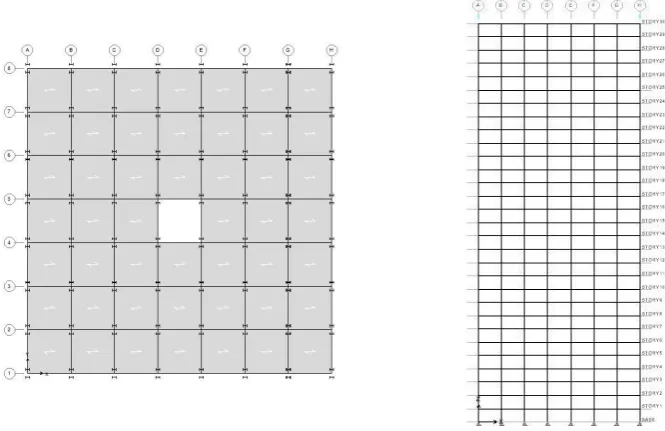
The main objective of the study is to perform the static and dynamic linear analysis of the plan regular steel structures. In this a typical commercial complex structures is selected which are in the rectangular shape of 7X7 bays, where each bay measures 5m. The plan of the building models selected for the analysis is shown in following fig respectively.
A. Description of the Analytical Model
Various parameters such as load intensities, material properties, dimensions of the structural members and the seismic data considered in the modeling of the structures are mentioned below.
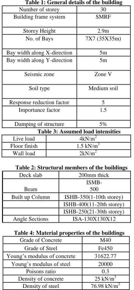
Table 1: General details of the building
Number of storey 30
Table 2: Structural members of the buildings
Deck slab 200mm thick
Beam
ISMB-500
Built up Column ISHB-350(1-10th storey) ISHB-400(11-20th storey) ISHB-250(21-30th storey) Angle Sections ISA-130X130X12
Table 4: Material properties of the buildings
Grade of Concrete M40 Grade of Steel Fe450 Young’s modulus of concrete 31622.77
Young’s modulus of steel 20000 Poisons ratio 0.3 Density of concrete 25 kN/m3
B. Analysis of the structure in ETABS (Extended Three Dimensional Analysis of Building Systems)
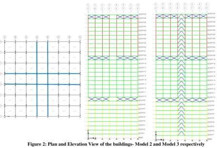
The plan of the structures selected in the study are modeled and analyzed in the ETABS nonlinear version 9.7.4. ETABS is a finite element software package, developed by a United States based computers and structures Inc, The following figures show the plan and elevation view of the models considered:
Figure 2: Plan and Elevation View of the buildings- Model 2 and Model 3 respectively IV. RESULTS AND DISCUSSIONS
The Parametric Evaluation of Lateral resistant Structural systems with varied structural configurations for the described models are modeled in ETABS has been performed and analyzed. The response of the different configuration structures is obtained.
The following are the parameters for which results are discussed:
Displacement, Storey Drift, Time Period and Base shear is obtained for each case. A. Modal Time Period
As per IS 1893:2002 The approximate fundamental natural period of vibration (Ta ), in seconds, of a moment-resisting frame building without brick infill panels may be estimated by the empirical expression:
Ta = 0.085 h0.75 for steel frame building where, h = Height of building
Based on the above formula, it can be defined that the natural time period mainly depends on the height of the building and base dimension of the building along the direction of the lateral force.
1. Time Period Results
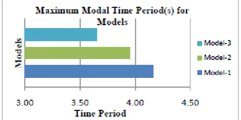
Figure 3: Graph showing Maximum Modal Time Period 2. Discussions
From the graph plotted it indicates that:
The fundamental time period of bare frame is 4.16sec and the model with the Outrigger with truss core is 3.65 which show the decrease in the time period for the Model-3. Hence, it can be seen that Model 3 is stiffer than the Model 1.
The fundamental natural time period for a tall building of 10-20 stories is in between 0.5-2 seconds. As the height of the building increases the mass of the building increases but its overall stiffness decreases. With the reference of the above tabulated results and graph, the natural period of the building increases due to the effect of mass of the building and the building height (30-stories). The regular model 1 is exhibiting higher flexibility compared to other models. Hence shows higher time period. However, the building of outrigger with truss core shows brittle and stiffer in nature compared with other models.
B. Base Shear
As per IS 1893:2002; the design base shear VB along any principal direction of a building is given by
VB = AhW
Ah = design horizontal acceleration co-efficient value
W= seismic weight of the building
Based on the above formula, it can be derived that the base shear mainly depends on the seismic weight of the building and design acceleration co-efficient which in turn depends on the fundamental time period, damping and the soil type
1. Base shear Results
Table 6: Base shear (kN) for different structural configuration of the structure in X and Y-direction for Equivalent Static Analysis(ESA) and Response Spectrum Analysis(RSA).
2. Discussions
From the above given formula, it can be inferred that the Base Shear increases as the increase in the mass of the structure. From the above given graph it is observed that the Base shear value for the Model 1- Bare frame is 6163 KN and for Model 2- Outrigger system 6180.63 KN. It infers that the mass of the Model 2 is greater than the mass of the Model 1 so exhibiting the maximum value of base shear.
As the base shear is also a dependent of time period, it is observed that due to reduced Time Periods and increased mass the horizontal co-efficient of forces increases and hence an increase in Base shear is observed.
Higher the natural period of structure means the more flexible the structure is. A flexible structure generally experiences lower accelerations than a stiff building. Now because a flexible building is hard to excite, it will have lower base shear which is seen in the Model1.
There is no much variation in the base shear value of ESA and RSA in X and Y direction. Since the base shear depends on the mass, height and dynamics of the building. There is only a minor variation and hence it is not of much concern.
C. Lateral Displacement
Displacement of the structure depends on the response of the structure inducing from the lateral forces. Higher the displacement of structure means the structure is more flexible. To maintain the structure stiffness, the displacement of the structure has to be within the limits. According to the codal provisions, the allowable displacement limit for the structures is H/500, where H = total height of the building.
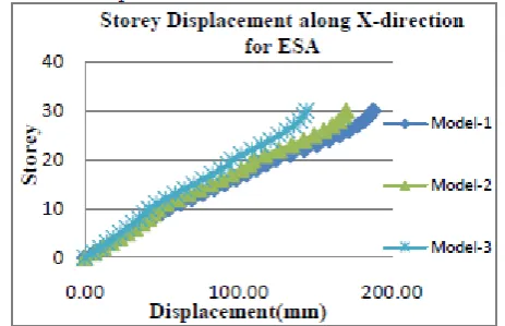
1. Displacement Results
Figure 7: Comparison of story v/s displacement for in Y direction for ESA
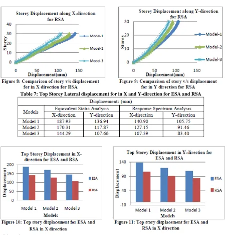
Table 7: Top Storey Lateral displacement for in X and Y-direction for ESA and RSA
It can be observed from the above graph, the pattern of the graph runs parabolically. From the fig.6 it is observed that maximum displacement seen in Model-1 (187.93 mm) and minimum is seen in Model-3 (144.29 mm) in X direction for ESA.
From the fig. 7 it is observed that maximum displacement seen in Model-1 (136.94 mm) and minimum is seen in Model-3 (107.66 mm) in Y direction for ESA.
From the fig. 8 it is observed that maximum displacement seen in Model-1 (140.9 mm) and minimum is seen in Model-3 (105.42 mm) in X direction for RSA.
From the fig. 9 it is observed that maximum displacement seen in Model-1 (105.75 mm) and minimum is seen in Model-3 (82.06 mm) in Y direction for RSA.
From the above limiting value of the displacement, it can derive that the displacement depends on the building height. As the building height increases the stiffness will decrease so to provide sufficient stiffness and to avoid more displacement of the building due to lateral forces lateral resisting outrigger structural system is provided.
From the above given points 2,3,4 and 5 it can be inferred that the displacement of Model-1 is very high compared to other structural models. However, the model with outrigger and shear band is very effective compared to other models. This proves to be efficient and reduction in displacement due to the provision of structural system.
From the table 6, it is noticed that the models provided with lateral force resisting structural system are under the allowable displacement limits compared with Model 1 which is bare frame. Bare frame is more flexible compared to the other models.
D. Storey Drift
As per IS 1893:2002; The storey drift in any storey due to the minimum specified design lateral force, with partial load factor of 1.0, shall not exceed 0.004 times the storey height. Hence as per the limiting value of the storey drift it can be derived that storey drift is a dependent of the building height.
2. Discussions
The storey drift plays a very good role in the prediction of earthquake resistance model.
From the fig. 13 it is observed that maximum storey drift seen in Model-1 (0.002886) and minimum is seen in Model-3 (0.002293) for ESA in X-direction.
From the fig. 14, it is observed that maximum storey drift seen in Model-1 (0.002169) and minimum is seen in Model-3 (0.001824) for ESA in Y-direction.
From the fig. 15 it is observed that maximum drift seen in Model-1 (0.002587) and minimum is seen in Model-3 (0.001837) for RSA in X-direction.
From the fig. 16 it is observed that maximum drift seen in Model-1 (0.002094) and minimum is seen in Model-3 (0.001767) for RSA in Y-direction.
From the above points it can be inferred that Model 3 is resisting drift efficiently and is stiffer and compared to all the other models. Model 1 is flexible and there is no lateral load resisting system so it is exhibiting more drift. Hence, the model 3 performance is better compared to all other models. By referring to the above clause, the models with the lateral load resisting system in the present study are within the limits.
It is observed that the story drifts at some point is reduced when the outrigger structural system is considered. In the fig 12, 13, 14, and 15 it is observed that, there is a dip in graph this is due to outrigger system effect.
V. CONCLUSIONS
ii. The Response spectrum analysis gives smaller results compared to Static analysis, there is reduction of about 24% in values. This clarifies, the ESA gives higher results and safe which will be sufficient while analyzing buildings of low rise and less importance.
iii. The storey drift values will always be in concurrence with the displacement values. The higher drift values are noticed in model 1 and lower in case of model 3. We can notice few dips in the graph, which indicates the presence of stiffener element, outrigger system.
iv. The time period of the model 1 is high due to the flexibility in the structure. However, the model 3 behaves stiffer, hence the time period is less. These buildings exhibit stiffness and stableness and also will show better performance towards the seismic analysis.
v. The base shear values are almost same in the all the models. The base shear depends on the mass, height and dynamics of the building. However, we can observe there is an almost equal mass and height of the building, there is not a much noticeable difference in the models. Hence, we can conclude that providing outrigger system will not change in Base shear value as it purely depends on the mass, height and dynamics of the building.
REFERENCES
[1] Goman W M Ho (2016) “The Evolution of Outrigger System in Tall Buildings” International Journal of High-Rise Buildings, Volume No.05, Issue No. 01, pp 21-30.
[2] Hi Sun Choi and Leonard Joseph (2012) “Outrigger System Design Considerations” International Journal of High-Rise Buildings, Volume No.01, Issue No. 03, pp 237-246.
[3] C. D. Hoenderkamp and M. C. M. Bakker (2003) “Analysis Of High-Rise Braced Frames With Outriggers” The Structural Design Of Tall and Special Buildings Struct. Design Tall Spec. Build 335– 350 in Wiley Interscience (www.interscience.wiley.com). DOI:10.1002/tal.226
[4] Z Bayati et. al., (2008) “Optimized use of Multi-Outriggers System to Stiffen Tall Buildings”, The 14th World Conference on Earthquake Engineering, Beijing, China.
[5] Kiran Kamth et. al., (2012) “A Study on Static and Dynamic Behaviour of Outrigger Structural System for Tall Buildings” International Journal of Industrial Engineering and Management Sciences, Volume No.02, Issue No. 04.
[6] IS 1893: 2002, “Criteria for Earthquake resistant design of Structures- Part1” [7] IS 800: 2007,” Code of Practice for General construction in Steel”