International Journal of Research in Advent Technology, Vol.2, No.5, May 2014
Adaptive JPEG 2000
Aman
1P. G. Student, Deptt. Of
Email:
Image compression techniques generally fall into two categories: lossless and lossy depending on the redundancy type exploited, where lossless also called information preserving or error free techniques, in which the image compressed without losing inform
remove content from the image, which degrades the compressed image quality, and are based on the utilization of psycho-visual redundancy, either solely or combined with statistical redund
quantization, fractal, transform coding and JPEG2000. In general, lossy techniques work on segment based that subdivide the image into non-overlapping segments (blocks) of fixed sizes or variab
partitioning methods utilized by a n using partitioning techniques such as techniques are available for the Single channel i
had been done on single channel image compression mostly based on JPEG
JPEG 2000 standard can able to provide smaller root mean square error but not able to gene
compression ratio. This arises the need of image compression techniques which can able to keep RMSE within an allowable range and simultaneously able to generate higher compression ratio (CR). This paper brought forward a mathematical modification on available JPEG 2000 image compression algorithm so that it can able to provide higher compression efficiency with allowable error rate.
KEYWORDS: - Single channel image compressions, JPEG
compression ratio (CR).
1. INTRODUCTION
The digital signal processing and multimedia Computing is used to produce and process a large number of images. Storing of raw image takes more space on storage device and more bandwidth over network during transmission. The proposed algorithm does compression of an image by reducing the size of pixel. The size of pixel is reduced
pixel using only required number of bits instead of 8 bits per color. The pre-processing step
valuing pixel based on occurrence to get better compression ratio. The process of reducing the amount of data needed for storage and transmission of given image on storage place is image compression. The compression helps to reduce transmission bandwidth case of network or satellite transmission.
Pixel Size Reduction lossy image compression algorithm will retain the originality of an i
it is decompressed. The image is represented as a matrix of pixel value
and each pixel for each color is represented in
value ranging from 0 to 255 occupying 8bits. The RGB image has 3 planes representing three primary namely Red, Green and Blue color as components of an image. The test images used to test the proposed algorithm are 24 bits color.The spatial and spectral redundancies are present because certain spatial and spectral patterns between the pixels and the components are common to each other, whereas the
International Journal of Research in Advent Technology, Vol.2, No.5, May 2014
E-ISSN: 2321-9637
JPEG 2000 Standard for Higher Compression
with Less Error
Kumar Chandrakar
1, Ramkishan Dewangan
Of CSE, CSIT durg india, 2Assistant Professor, Deptt. Of CSE, CSIT durgEmail: [email protected], [email protected]
Image compression techniques generally fall into two categories: lossless and lossy depending on the redundancy type exploited, where lossless also called information preserving or error free techniques, in which the image compressed without losing information that rearrange or reorder the image content, while lossy which remove content from the image, which degrades the compressed image quality, and are based on the utilization visual redundancy, either solely or combined with statistical redundancy such as such as vector quantization, fractal, transform coding and JPEG2000. In general, lossy techniques work on segment based that
overlapping segments (blocks) of fixed sizes or variable sizes. The
ioning methods utilized by a number of researchers to overcome the fixed partitioning method drawback using partitioning techniques such as quad tree, HV (horizontal-vertical) and triangular
ingle channel image compression i.e. for gray images. Since then lots of work had been done on single channel image compression mostly based on JPEG 2000 compressi
standard can able to provide smaller root mean square error but not able to gene
compression ratio. This arises the need of image compression techniques which can able to keep RMSE within an allowable range and simultaneously able to generate higher compression ratio (CR). This paper brought ion on available JPEG 2000 image compression algorithm so that it can able to provide higher compression efficiency with allowable error rate.
Single channel image compressions, JPEG 2000 standard, mean square error (MSE),
The digital signal processing and multimedia Computing is used to produce and process a large images. Storing of raw image takes more space on storage device and more bandwidth over proposed algorithm does compression of an image by reducing the size of pixel. The size of pixel is reduced by representing pixel using only required number of bits instead of 8 processing step takes care of re-uing pixel based on occurrence to get better
The process of reducing the amount of data needed for storage and transmission of given on storage place is image compression. The compression helps to reduce transmission bandwidth in transmission. The proposed image compression algorithm will retain the originality of an image when The image is represented as a
or is represented in integer value ranging from 0 to 255 occupying 8bits. The RGB three primary colors namely Red, Green and Blue color as components of images used to test the proposed The spatial and spectral redundancies are present because certain spatial and spectral patterns between the pixels and the colour components are common to each other, whereas the
psycho-visual redundancy originates from the fact that the human eye is insensitive to certain spatial frequencies. The principle of image compression algorithms are (i) reducing the redundancy in the image data and (or) (ii) producing a reconstructed image from the original image with the introduction of error that is insignificant to the intended applications. The aim here is to obtain an acceptable representation of digital image while preserving the essential information contained in that particular data set.
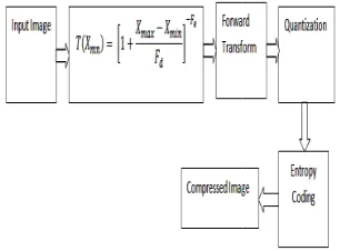
Figure1Image compressions System
The problem faced by image compression is very easy to define, as demonstrated in figure 1. First the original digital image is usually transformed into another domain, where it is highly de-correlated by using some transform. This de-correlation concentrates the important image information into a more compact form. The compressor then removes the redundancy in the transformed image and stores it into a compressed file or data stream. In the second stage, the quantization block reduces the accuracy of the transformed output in accordance with some pre
International Journal of Research in Advent Technology, Vol.2, No.5, May 2014
Standard for Higher Compression
CSE, CSIT durg india
Image compression techniques generally fall into two categories: lossless and lossy depending on the redundancy type exploited, where lossless also called information preserving or error free techniques, in which ation that rearrange or reorder the image content, while lossy which remove content from the image, which degrades the compressed image quality, and are based on the utilization ancy such as such as vector quantization, fractal, transform coding and JPEG2000. In general, lossy techniques work on segment based that le sizes. The variable block to overcome the fixed partitioning method drawback vertical) and triangular method. Lots of Since then lots of work compression. The available standard can able to provide smaller root mean square error but not able to generate higher compression ratio. This arises the need of image compression techniques which can able to keep RMSE within an allowable range and simultaneously able to generate higher compression ratio (CR). This paper brought ion on available JPEG 2000 image compression algorithm so that it can able
standard, mean square error (MSE),
visual redundancy originates from the fact that eye is insensitive to certain spatial frequencies. The principle of image compression algorithms are (i) reducing the redundancy in the data and (or) (ii) producing a reconstructed image from the original image with the introduction of insignificant to the intended applications. The aim here is to obtain an acceptable representation of digital image while preserving the essential information contained in that particular data set.
Image compressions System
criterion. Also this stage reduces the psycho redundancy of the input image. Quantization operation is a reversible process and thus may be omitted when there is a need of error free or lossless comp
the final stage of the data compression model the symbol coder creates a fixed or variable
represent the quantizer output and maps the output in accordance with the code. Generally a variable code is used to represent the mapped and quantized data set. It assigns the shortest code words to the most frequently occurring output values and thus reduces coding redundancy. The operation in fact is a reversible one. The decompression reverses the compression process to produce th
as shown in figure 2. The recovered image may have lost some information due to the compression, and may have an error or distortion compared to the original image.
Figure2 Image decompression
2. BASIC ARCHITECTURE OF
STANDARD
The block diagram of the JPEG2000 encoder is illustrated in Fig. 3(a). The discrete transform is first applied on the source image data. The transform coefficients are then quantized and entropy coded, before forming the output code stream (
The decoder is the reverse of the encoder (Fig.4.1b). The code stream is first entropy decoded, de
and inverse discrete transformed, thus resulting in the reconstructed image data. Before proceeding with the details of each block of encoder in Fig. 1, it should be mentioned that the standard works on image tiles. The term ‘tiling’ refers to the partition of the original (source) image into rectangular non
blocks (tiles), which are compressed independently, as though they were entirely distinc
computation of the forward discrete wavelet transform (DWT) on each image tile, all samples of the image tile component are DC level shifted by subtracting the same quantity (i.e. the component depth). DC level shifting is performed on samples of components that are unsigned only. If colour transformation is used, it is performed prior to computation of the forward component transform. Otherwise it is performed prior to the wavelet transform.
At the decoder side, inverse DC level shifting is performed on reconstructed samples of components that are unsigned only. If used, it is performed after the computation of the inverse component transform. Arithmetic coding is used in the last part of the encoding process. The MQ coder is adopted in JPEG2000. This coder is basically similar to the QM criterion. Also this stage reduces the psycho-visual redundancy of the input image. Quantization operation is a reversible process and thus may be omitted when there is a need of error free or lossless compression. In the final stage of the data compression model the symbol coder creates a fixed or variable-length code to represent the quantizer output and maps the output in accordance with the code. Generally a variable-length mapped and quantized data set. It assigns the shortest code words to the most frequently occurring output values and thus reduces coding redundancy. The operation in fact is a The decompression reverses the compression process to produce the recovered image as shown in figure 2. The recovered image may have lost some information due to the compression, and may have an error or distortion compared to the original
Figure2 Image decompression System
THE JPEG2000
The block diagram of the JPEG2000 encoder is . The discrete transform is first applied on the source image data. The transform coefficients are then quantized and entropy coded, before forming the output code stream (bit stream). The decoder is the reverse of the encoder (Fig.4.1b). The code stream is first entropy decoded, de-quantized and inverse discrete transformed, thus resulting in the Before proceeding with the encoder in Fig. 1, it should be mentioned that the standard works on image tiles. The term ‘tiling’ refers to the partition of the original (source) image into rectangular non-overlapping blocks (tiles), which are compressed independently, as ere entirely distinct images. Prior to computation of the forward discrete wavelet transform (DWT) on each image tile, all samples of the image tile component are DC level shifted by subtracting the same quantity (i.e. the component depth). DC level ng is performed on samples of components that are unsigned only. If colour transformation is used, it is performed prior to computation of the forward component transform. Otherwise it is performed prior rse DC level shifting is performed on reconstructed samples of components that are unsigned only. If used, it is performed after the computation of the inverse component transform. Arithmetic coding is used in the last part of the coder is adopted in JPEG2000. This coder is basically similar to the QM-
coder adopted in the original JPEG standard [1]. The MQ-coder is also used in the JBIG
recapitulate, the encoding procedure is as follows [8, 9]:
• The source image is decomposed into components.
• The image and its components are decomposed into rectangular tiles. The tile
basic unit of the original or reconstructed image.
• The wavelet transform is applied on each tile. The tile is decomposed in differen
levels.
• These decomposition levels are made up of bands of coefficients that describe the frequency characteristics of local areas (rather than across the entire tile-component) of the tile component.
• The sub bands of coefficients are quan collected into rectangular arrays of “code
• The bit-planes of the coefficients in a “code are entropy coded.
• The encoding can be done in such a way, so that certain ROI’s can be coded in a higher quality than the background.
• Markers are added in the bit stream to allow error resilience.
• The code stream has a main header at the beginning that describes the original image and the various decomposition and coding styles that are used to locate, extract, decode and reconstruct the image with the desired resolution, fidelity, region of interest and other characteristics.
• The optional file format describes the meaning of the image and its components in the context of the application. It should be noted here that the basic encoding engine of JPEG2000 is based on EBCOT (Embedded Block Coding with Optimized Truncation of the embedded streams) algorithm, which is described in details in [20, 21].
Fig.3 Block diagram of the JPEG 2000
coder adopted in the original JPEG standard [1]. The coder is also used in the JBIG-2 standard [7]. To recapitulate, the encoding procedure is as follows [8, s decomposed into The image and its components are decomposed into rectangular tiles. The tile-component is the basic unit of the original or reconstructed image. The wavelet transform is applied on each tile. The tile is decomposed in different resolution These decomposition levels are made up of sub of coefficients that describe the frequency characteristics of local areas (rather than across component) of the tile component.
of coefficients are quantized and collected into rectangular arrays of “code-blocks”.
planes of the coefficients in a “code-block” The encoding can be done in such a way, so that certain ROI’s can be coded in a higher quality s are added in the bit stream to allow error has a main header at the beginning that describes the original image and the various decomposition and coding styles that are used to locate, extract, decode and reconstruct with the desired resolution, fidelity, region of interest and other characteristics. The optional file format describes the meaning of the image and its components in the context of the application. It should be noted here that the f JPEG2000 is based on EBCOT (Embedded Block Coding with Optimized Truncation of the embedded bit ) algorithm, which is described in details
Fig.4.Tiling DC level shifting and DWT of image each tile
3. PROPOSED METHODOLOGY
The methodology of this paper proposes
modification of the available JPEG 2000 for achieving higher compression as compared to the available JPEG 2000 standard. Hence first part of this
modify JPEG 2000 termed as modified JPEG 2000. The basic idea of JPEG 2000 is discussed in
the main modification is the preprocess the image with a transfer function given by equation
the image more suitable for JPEG 200
hence able to provide higher compression with less error. The modified JPEG 2000 proposed is shown in figure (5).
1
Where , are constants, and = Maximum gray value of input image.
= Mid gray value of input image.
0.5 1
And N is the new transformed image, which is suitable for JPEG compression.
Figure (5) Modified JPEG2000
Effect of Proposed modification
It is commonly found that most of the image compression techniques based on lossy image compression provides good compression ratio. Most of the times the input image is a raw image.
work deals with the development of transfer function that can make input image more suitable so that the
level shifting and each tile
ETHODOLOGY
proposes a serious modification of the available JPEG 2000 for achieving higher compression as compared to the available JPEG 2000 standard. Hence first part of this paper is to modify JPEG 2000 termed as modified JPEG 2000. The basic idea of JPEG 2000 is discussed in figure (3), process the image with a transfer function given by equation (1), which makes the image more suitable for JPEG 2000 technique and hence able to provide higher compression with less error. The modified JPEG 2000 proposed is shown in
= Maximum gray value of
And N is the new transformed image, which is suitable
2000-DWT
Effect of Proposed modification
It is commonly found that most of the image compression techniques based on lossy image compression provides good compression ratio. Most of the input image is a raw image. This project pment of transfer function that can make input image more suitable so that the
same algorithm will provide higher compression ratio as compare to previous case when the image is in raw form. There are two important reasons, why algorithms provide less compression ratio when input image raw form.
1) In Most of the cases input image has high contrast,
in that case compression technique has to keep large no. of pixels to track contrast changes and hence compression ratio is decreased.
2) In some cases input image has good brightness, in
that case compression technique has to keep again large no. of pixels to track Brightness changes and hence compression ratio is again decreased.
To increase the compression ratio, possible solution is
1) Decrease the Contrast of input image while keeping
contrast information of original image.
2) Decrease the Brightness of input image while
keeping brightness information of original image. During implementation of this concept one possible problem is the retaining of con
information during proposed transformation, for the solution of this problem lot of algorithms are already available to stretch the contrast and brightness level of images after reconstruction. Below table
effect of proposed transfer function on raw input image, and it is observable that proposed transfer function effectively reduces the contrast and brightness level of input image so that higher compression can be achieve during compression. The proposed modification function is plotted in following figure.
For example let’s consider the input matrix is 11 16 78
22 14 36
The output matrix after using the proposed function is given as
0.4259 0.4306 0.4993 0.4363 0.4287 0.4503
The values obtained in the output matrix clearly indicated that all the pixel values are transferred in approximately same values and values reduced leads to reduction in brightness and values lies in same values indicates the reduction in contrast of the image.
4. RESULTS AND DISC
The algorithm has been successfully developed and implemented in MATLB 7.10 to develop an efficient gray image compression. The following section deals with the description and discussion about
0 50 100 150
0.4 0.5 0.6 0.7 0.8 0.9 1
same algorithm will provide higher compression ratio as compare to previous case when the image is in raw form. There are two important reasons, why algorithms ression ratio when input image is in In Most of the cases input image has high contrast, in that case compression technique has to keep large no. of pixels to track contrast changes and hence
input image has good brightness, in that case compression technique has to keep again large no. of pixels to track Brightness changes and hence compression ratio is again decreased.
To increase the compression ratio, possible solution is ntrast of input image while keeping contrast information of original image.
Decrease the Brightness of input image while keeping brightness information of original image. During implementation of this concept one possible problem is the retaining of contrast and brightness information during proposed transformation, for the solution of this problem lot of algorithms are already available to stretch the contrast and brightness level of after reconstruction. Below table shows the transfer function on raw input image, and it is observable that proposed transfer function effectively reduces the contrast and brightness level of input image so that higher compression can be achieve during compression. The proposed modification
is plotted in following figure.
For example let’s consider the input matrix is
The output matrix after using the proposed function is .4259 0.4306 0.4993
0.4363 0.4287 0.4503
he output matrix clearly indicated that all the pixel values are transferred in approximately same values and values reduced leads to reduction in brightness and values lies in same values indicates the reduction in contrast of the image.
ESULTS AND DISCUSSIONS
The algorithm has been successfully developed and to develop an efficient following section deals with the description and discussion about various
[image:3.595.307.495.418.572.2] [image:3.595.106.259.535.648.2]results obtained from the developed algorithm and normal JPEG 2000. Since it is not possible to estimate the performance of any algorithm on the basis of single image, hence for the performance evaluation of the developed algorithm three different gray images has been used. These images are shown in figure (6), figure (7) and figure (8). To compare the results obtained from the developed algorithm and normal JPEG 2000 two most important image compression parameters are used.
1) Compression Ratio (CR).
2) Root Mean Square Error (RMSE).
To show the compression and decompression process by using developed algorithm on first input image i.e. autumn.tif. Whose size is 206X345 and memory requirement to store is 71070 bytes shown in figure (6). For the performance assessment of developed algorithm on compression and decompression processes, the value of parameter level of decomposition is fixed to 5. The results obtained after the compression and decompression process using normal JPEG 2000 (NJPEG2000) and Modified JPEG 2000 (MJPEG2000) are shown from figure (6.1), figure (6.2) and figure (6.3).
Figure (6.1) input image.
Figure (6.2) Output image using (NJPEG2000)
Figure (6.3) Output image using (MJPEG2000) The compression parameters obtained after first input image compression and decompression process using NDWT and FDWT are as follows.
Parameters
Results for NJPEG2K
Result MJPEG2
Bi (size of first input image in
bytes)
71070 bytes. 71070 bytes.
Bc (size of first compressed image in bytes)
66256 bytes. 2884 bytes.
Bo (size of first decompressed image in bytes)
71070 bytes. 71070 bytes.
Cr1 22.9703 197.1429
R.M.S.E1 10.9844 35.1643
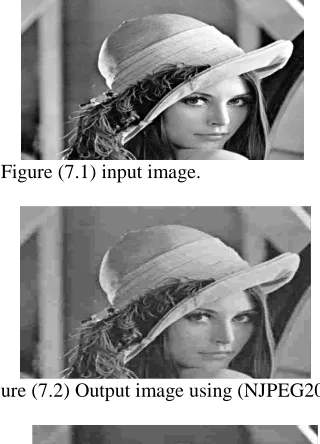
Similarly the results obtained for second input image i.e. (lena.jpeg), who’s Size, is 415X445 and memory requirement to store is 180525 bytes are shown from figure (7.1) to figure (7.3). The compression parameters obtained after Second input image compression and decompression process using normal JPEG 2000 (NJPEG2000) and Modified JPEG 200 (MJPEG2000) are as follows.
Figure (7.1) input image.
Figure (7.2) Output image using (NJPEG2000)
Figure (7.3) Output image using (MJPEG2000)
S. No. Parameters Results for
NJPEG2000
Results for MJPEG2000
1
Bi (size of first input image in
bytes)
180525 bytes.
[image:4.595.326.497.70.245.2] [image:4.595.307.518.334.754.2] [image:4.595.94.282.351.634.2] [image:4.595.331.491.363.585.2]2
Bc (size of first compressed image
in bytes)
121096
bytes. 7334 bytes.
3
Bo (size of first decompressed image in bytes)
180525 bytes.
180525 bytes.
4 Cr2 30.6807 196.9185
5 R.M.S.E2 8.1344 34.2543
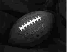
Again the results obtained for Third input image i.e. (football.jpeg) Size 256X320 and memory requirement to store is 81920 bytes are shown from figure (8.1) to figure (8.3). The compression parameters obtained after third input image compression and decompression process using normal JPEG 2000 (NJPEG2000) and Modified JPEG 2000 (MJPEG2000) are as follows.
Figure (8.1) input image.
Figure (8.2) Output image using (NJPEG2000)
Figure (8.3) Output image using (MJPEG2000)
S.
No. Parameters
Results for NJPEG2000
Results for MJPEG2000
1 Bi (size of first input
image in bytes) 81920 bytes. 81920 bytes.
2
Bc (size of first compressed image in
bytes)
42336 bytes. 1878 bytes.
3
Bo (size of first decompressed image in
bytes)
81920 bytes. 81920 bytes.
4 Cr3 39.1587 348.9670
5 R.M.S.E3 9.5739 44.9676
V. CONCLUSIONS
In this Modern area image Transmission and processing plays a major role, and during the transmission and reception the image storage plays very important and crucial role. In the present scenario the technology development wants fast and efficient result production capability. This paper has brought forward some serious modifications on available JPEG 2000 image compression method. After the successful implementation of the proposed modification it has been found the modification proposed in conventional JPEG 2000 leads to the efficient solution to provide higher compression as compare to available JPEG 2000.
In addition to this in the result section it is found that though the proposed modification generates very high compression ratio but simultaneously increases the compression error. The key concept behind the acceptance of this increment in the compression error is that the change in error percentage is very small as compare to change in compression ratio. Hence the proposed modified JPEG 2000 provides efficient compression for gray scale images.
REFERENCES
[1] Rao, K. R. and Yip, P.(1990), Discrete Cosine Transform: Algorithms, Advantages and Applications. San Diego, CA: Academic, . [2] Gortler. S., Schroder, P., Cohen, M., and
Hanrahan, P.(1993), "Wavelet Radiosity", in Proc. SIGGRAPH, pp. 221-230, .
[3] Berman, D., Bartell, J. and Salesin, D(1994)., "Multiresolution Painting and Compositing", in Proc. SIGGRAPH, pp. 85-90, .
[4] Finkelstein. A. and Salesin, D.(1994), "Multiresolution Curves", in Proc. SIGGRAPH, pp.261-268, .
[image:5.595.75.528.69.305.2] [image:5.595.114.254.325.567.2] [image:5.595.114.254.594.703.2]"Multiresolution Analysis of Arbitrary Meshes", in Proc. SIGGRAPH, pp. 173-182, .
[6] Lippert, L. and Gross, M.(1995), "Fast Wavelet Based Volume Rendering by Accumulation of Transparent Texture Maps", in Proc. EUROGRAPHICS, pp. 431-443, .
[7] Jacobs, C., Finkelstein, A. and Salesin, D(1995)., "Fast Multiresolution Image Querying", in Proc. SIGGRAPH, pp. 277-286, .
[8] Andrew B. Watson NASA Ames Research Centre (1994) “Image Compression Using the Discrete Cosine Transform”Mathematica Journal, 4(1), , p. 81-88.
[9] Ujjaval Y. Desai, Marcelo M. Mizuki, Ichiro Masaki, and Berthold K.P. Horn(1996) “Edge and Mean Based Image Compression” ARTIFICIAL INTELLIGENCE LABORATORY A.I.
Memo No. 1584 November, .
[10] Carmen de Sola Fabregas, Nguyen Phu Tri (1997)“Ultrasound Image Coding using Shape Adaptive DCT and Adaptive Quantization” Proc. of the Conference on Medical Images, vol. 3031, 1997, p. 328-330 IEEE, .
[11] F.G. Meyer and A.Z. Averbuch and J.O. Stromberg and R.R. Coifman(1998)“Multi-layered Image Compression” International Conference on Image Processing (ICIP'98) Volume 2.
[12] David Taubman, Member, IEEE(2000) “High Performance Scalable Image Compression with EBCOT “IEEE TRANSACTIONS ON IMAGE PROCESSING, VOL. 9, NO. 7,.
[13] Luciano VolcanAgostini, Ivan Saraiva Silva & Sergio Bampi(2001)“Pipelined Fast 2-D DCT Architecture for JPEG Image Compression” published in Integrated Circuits and Systems. [14] RebeckaJornsten, Bin Yuy& Wei Wang,
KannanRamchandranz(2003)“MICROARRAY IMAGE COMPRESSION AND THE EFFECT OF COMPRESSION LOSS” Science Direct, Signal Processing, Volume 83, Issue 4, Pages 859-869.
[15] Emma SofiJonasson(2005)“Document Segmentation for Image Compression” A thesis submitted to Clayton School of Information Technology Monash University in November. [16] NikolayPonomarenko, Vladimir Lukin, Karen
Egiazarian and JaakkoAstola(2005)“DCT Based High Quality Image Compression” Proceedings of 14th Scandinavian Conference On Image Analysis, Joensuu, Finland, pp. 1177-1185, June,. [17] C. Kwan, B. Li, R. Xu, X. Li, T. Tran, and T. Nguyen(2006) “A Complete Image Compression Scheme Based on Overlapped Block Transform with Post-Processing” Hindawi Publishing Corporation EURASIP Journal on Applied Signal Processing Volume Article ID 10968, Pages 1– 15 DOI 10.1155/ASP//10968.
[18] Mr. T. Sreenivasulureddy Ms. K. Ramani Dr. S. Varadarajan Dr. B.C.Jinaga(2007)“Image Compression Using Transform Coding Methods” IJCSNS International Journal of Computer Science and Network Security, VOL.7 No.7. [19] Nileshsingh V. Thakur and Dr. O. G.
Kakde(2007)“Color Image Compression with Modified Fractal Coding on Spiral Architecture” JOURNAL OF MULTIMEDIA, VOL. 2, NO. 4, . [20] Mark S. Drew and Steven Bergner (2005)“Spatio-Chromatic Decorrelation for Colour Image Compression” Image Communication, Volume 23 Issue 8.
About Authors:
Aman Kumar Chandrakar received the B.E. From Chhattisgarh Swami Vivekananda Technical University, Bhilai (C.G.), India in Computer Science & Engineering in the year 2012. He is currently pursuing M.Tech. Degree in Computer Science & Engineering from CSVTU Bhilai (C.G.)India. His research area is in Digital Image Processing.