ABSTRACT
ZHANG, YUEMEI. Density Functional Analysis of the Spin Exchange Interaction and Spin-Orbit Coupling in some Magnetic Oxides of Transition-Metal Elements. (Under the direction of Prof. Mike H. Whangbo).
Transition-metal magnetic oxides containing unpaired spins have low-lying excited states with different spin moments and hence exhibit a variety of magnetic properties as a function of temperature. Analysis of the nature and strengths of the spin exchange interactions between localized spins provides essential information in understanding the magnetic properties of magnetic oxides. Although spin-orbit coupling (SOC) interaction is weak, it can play a crucial role in determining the magnetic properties of transition-metal oxides with unpaired spins. In our research we investigate the magnetic and electronic properties of magnetic materials based on transition-metal oxides by examining spin exchange interactions and SOC effect on the basis of first principles density functional theory calculations.
One of the consequences of SOC is uniaxial magnetism. It is important to note that the electronic structure required for uniaxial magnetism is also the condition leading to Jahn-Teller (JT) instability. To investigate the competition between uniaxial magnetism and JT instability, we examined the recently discovered multiferroic compound Ca3CoMnO6, and its
analogues Ca3CoMO6 (M = Co, Rh, Ir) based on density functional calculations including
on-site repulsion and SOC. Ca3CoMnO6 is found to undergo a Jahn-Teller distortion thereby
losing uniaxial magnetism but retain substantial magnetic anisotropy. Our analysis of Ca3CoMO6 (M = Co, Rh, Ir) reveals that the magnetic and electronic properties of these
Another outcome of SOC is multiferroicity. The magnetic structure and ferroelectric polarization of the layered triangular multiferroic antiferromagnet CuFeO2 were examined on
the basis of density functional calculations, and were compared with those of the isostructural analogue AgCrO2. We explored why CuFeO2 requires a magnetic field applied along the
c-axis to adopt a helical spiral-spin structure but AgCrO2 does not, and how the ferroelectric
polarization of CuFeO2 is related to the asymmetric electron density distribution induced by
helical spiral-spin order and to the handedness of the helical spin rotation.
On the basis of density functional calculations, we evaluated the spin exchange interactions of the layered magnetic oxides YBaM2O5 (M = Mn, Fe, Co) by performing
mapping analysis to find that their strong inter-slab spin exchange leads to a three-dimensional magnetic ordering at high temperature, and estimated the relative stabilities of the checkerboard and stripe charge order patterns of YBaM2O5 (M = Mn, Fe, Co) to find that
Density Functional Analysis of the Spin Exchange Interaction and Spin-Orbit Coupling in some Magnetic Oxides of Transition-Metal Elements
by Yuemei Zhang
A dissertation submitted to the Graduate Faculty of North Carolina State University
in partial fulfillment of the requirements for the degree of
Doctor of Philosophy
Chemistry
Raleigh, North Carolina 2011
APPROVED BY:
_______________________________ ______________________________
Mike H. Whangbo Paul A. Maggard
Committee Chair
________________________________ ________________________________
DEDICATION To my parents and my husband.
BIOGRAPHY
ACKNOWLEDGMENTS
First I would like to acknowledge my research advisor, Professor Mike H. Whangbo. Without his expert guidance, advice, stimulating suggestions, and encouragement, this work would not have been possible. I am very happy and lucky to have worked in his group for the past few years and learned a lot from this smart and successful scientist. I also want to thank my committee members, Professor Paul A. Maggard, Professor David A. Shultz, and Professor Jerry L. Whitten for reading my dissertation and giving me important suggestions.
I would like to express my gratitude to the entire Whangbo group Chang-hoon, Erjun, Hongjun, Won-joon, Dr. Koo, Hyun-Joo, Chuan, Fang, Jia, Jin-hee and Jerry. I got a lot of help from all the former and current group members, and I own them from the deepest of my heart.
The graduate experience I found at NCSU has been one of the most positive experiences of my life. While Raleigh is a beautiful place to live, it is the community of people which makes this place so special. Thank you all for becoming part of my life.
I would also like to think my friends, xinai and xing. Your friendship is a very important part of my life.
TABLE OF CONTENTS
LIST OF TABLES………...vii
LIST OF FIGURES………..……….x
CHAPTER 1. INTRODUCTION………..………….1
REFERENCES………15
CHAPTER 2. INTERPLAY BETWEEN JAHN-TELLER INSTABILITY, UNIAXIAL MAGNETISM AND FERROELECTRICITY IN Ca3CoMnO6……….……….20
REFERENCES………34
CHAPTER 3. DENSITY FUNCTIONAL THEORY ANALYSIS OF THE INTERPLAY BETWEEN JAHN-TELLER INSTABILITY, UNIAXIAL MAGNETISM, SPIN ARRANGEMENT, METAL-METAL INTERACTION AND SPIN-ORBITAL COUPLING IN Ca3CoMO6 (M = Co, Rh, Ir)………..……….44
REFERENCES………64
CHAPTER 4. DENSITY FUNCTIONAL INVESTIGATION OF THE MAGNETIC STRUCTURE AND FERROELECTRIC POLARIZATION OF THE LAYERED TRIANGULAR ANTIFERROMAGNET CuFeO2 UNDER MAGNETIC FIELD…...…….90
REFERENCES……….………103
CHAPTER 5. DENSITY FUNCTIONAL ANALYSIS OF THE SPIN EXCHANGE INTERACTION AND CHARGE ORDER PATTERNS IN THE LAYERED MAGNETIC OXIDES YBaM2O5 (M = Mn, Fe, Co)….………..………...114
LIST OF TABLES
Table 2.1. Energy difference ΔE between the ↑↓↑↓ and the ↑↑↓↓ states of Ca3CoMnO6, ΔE = E↑↑↓↓ – E↑↓↑↓, obtained from LDA+U+SOC calculations as a function of the on-site repulsions on the Mn and Co atoms (UMn and UCo, respectively)………..….36
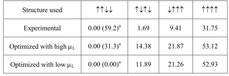
Table 2.2. Relative energies (in meV/f.u.) of the four ordered spin states of Ca3CoMnO6
determined from LDA+U+SOC calculations UMn=UCo=1.1 eV………....36
Table 2.3. Relative energies (in meV/f.u.) of the ↑↓↑↓ and ↑↑↓↓ states of Ca3CoMnO6
determined from LDA+U+SOC calculations with UMn=UCo= 2.1 and 4.1 eV………37
Table 2.4. Spin and orbital moments of the Co2+ and Mn4+ ions of Ca3CoMnO6 in the ↑↑↓↓
state determined from LDA+U+SOC calculations with UMn = UCo = 1.1, 2.1 and 4.1 eV….38
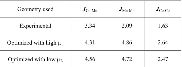
Table 2.5. Spin-exchange parameters (in meV) of Ca3CoMnO6 extracted from
LDA+U+SOC calculations with UMn=UCo=1.1 eV……….39
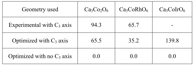
Table 3.1. Relative energies ΔE (meV/FU) of the experimental and optimized structures of Ca3CoMO6 (M = Co, Rh, Ir) obtained from the LSDA+U+SOC calculations using the PAW
method of the VASP with Ueff = 4 eV for Co and Ueff = 2 eV for M = Rh and Ira…………..67
Table 3.2. Spin and orbital moments (μS and μL, respectively) of the TP and OCT Co3+ ions
in the FM state of Ca3Co2O6 obtained from the LSDA+U+SOC (WIEN2k)a calculations
Table 3.3. Spin and orbital moments (μS and μL, respectively) of the TP Co2+ and OCT
Rh4+ ions in the FM state of Ca3CoRhO6 obtained from the LSDA+U+SOC (WIEN2k)
calculations with Ueff (Co) = Ueff (Rh) = 4 eVa,b………..………69
Table 3.4. Spin and orbital moments (μS and μL, respectively) of the TP Co2+
and OCT Ir4+ ions in the AFM state of Ca3CoIrO6 obtained from the
LSDA+U+SOC (WIEN2k) calculations with Ueff (Co) = Ueff (Ir) = 4 eVa,b………..….70
Table S3.1. Fractional coordinates of the optimized structures of Ca3Co2O6
from LDA+U+SOC (VASP) calculations (see the text)………..…82
Table S3.2. Fractional coordinates of the optimized structures of Ca3CoRhO6
from LDA+U+SOC (VASP) calculations (see the text)………..…83
Table S3.3. Fractional coordinates of the optimized structures of Ca3CoIrO6
from LDA+U+SOC (VASP) calculations (see the text)………..……84
Table S3.4. Slater-type atomic orbital parameters used for extended Hückel
tight binding calculationsa………..………..85
Table 4.1. Spin exchange energies (per FU) of the ↑↑↓↓, Qa+b (q = 1/3, 1/4, 1/5)
and ↑↑↑↓↓ states of CuFeO2 and AgCrO2
in terms of their spin exchange parameters J1 – J4……….107
Table 5.1. Relative energies (in meV per FU) of the FM, A-type AFM and G-type AFM spin arrangements (defined in Fig. 5.3) of YBaMn2O5
Table 5.2. Relative energies (meV per FU) of various ordered spin states
of YBaM2O5 (M = Mn, Fe, Co) determined from the DFT+U calculations………..…128
Table 5.3. Values of the spin exchange parameters Ji (in meV) of YBaM2O5
(M = Mn, Fe, Co) determined by mapping analysis based on DFT+U calculations……….129
Table S5.1. Coefficients Ci of the spin exchange parameters Ji
in the total spin exchange energy per FU, =
∑
ii i spin CJ
E ,
for the various ordered spin states of YBaMn2O5 defined in Fig. 5.4………...135
Table S5.2. Coefficients Ci of the spin exchange parameters Ji
in the total spin exchange energy per FU, =
∑
ii i spin CJ
E ,
for the various ordered spin states of YBaFe2O5 defined in Fig. 5.5……….136
Table S5.3. Coefficients Ci of the spin exchange parameters Ji
in the total spin exchange energy per FU, =
∑
ii i spin CJ
E ,
LIST OF FIGURES
Figure 1.1. Orbital interaction between two spin sites described by the magnetic orbitals
φ1 and φ2 leading to the dimer levels ψ1 and ψ2 separated by the energy gap Δe…………...18
Figure 1.2. (a) Two degenerate electron configurations of (Me3Si)3C-Fe-C(SiMe3)3
containing a high-spin Fe2+ (d6) ion in the linear two-coordinate site. (b) Correspondence between the Cartesian and the spherical-harmonics
representations for the split d-states of the linear-two coordinate Fe2+ (d6) ion…………..…18
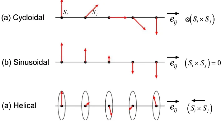
Figure 1.3. Schematic illustration of three types of magnetic structures in a 1D chain
of magnetic ions: (a) cycloidal, (b) sinusoidal, and (c) screw (or helical)………..…….19
Figure 2.1. (Color online) (a) Projection view of the crystal structure of Ca3CoMnO6
along the c direction. (b) Perspective view of an isolated CoMnO6 chain.
(c) Arrangement of nine Ca atoms surrounding one CoO6 trigonal prism,
in which the edges of the O3 triangles and the O4 rectangles are capped by Ca.
(d) Four-ordered spin arrangements of a single CoMnO6 chain, where the large
and small circles represent the Co2+ and Mn4+ ions, respectively, and the up and
down spins are represented by the absence and presence of shading, respectively………....40
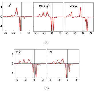
Figure 2.2. (Color online) (a) PDOS plots of the Co 3d states calculated for the ↑↑↓↓ state of Ca3CoMnO6 using the experimental structure, which has the C3 rotational symmetry. The
PDOS plots for the xy and x2−y2 states are identical and so are those of the xz and yz states. (b) PDOS plots of the Co 3d states calculated for the ↑↑↓↓ state of Ca3CoMnO6 using the
optimized structure with Jahn-Teller distortion (i.e., without C3 rotational symmetry).
For simplicity, only the PDOS plots for the xy and x2−y2 states are shown.
the up-spin and down-spin states, respectively)………..……41
Figure 2.3. (Color online) Displacements of the atoms associated with the Jahn-Teller distortions in the (a) ↑↑↓↓ and (b) ↑↑↑↑ states of Ca3CoMnO6 with respect to
their positions of the experimental structure………....42
Figure 2.4. (Color online) (a) Magnetic orbital contained in one MnO4 equatorial plane
of an isolated MnO6 octahedron. (b) MnO4 equatorial planes of two adjacent
MnO6 octahedra sharing one face of the intervening CoO6 trigonal prism.
(c) Projection view of the two magnetic orbitals associated with the two MnO4
equatorial planes in (b). (d) Magnetic orbital of an isolated CoO6 trigonal prism.
(e) Rectangular faces of two adjacent CoO6 trigonal prisms sharing an equatorial plane
of the intervening MnO6 octahedron………..……..43
Figure 3.1. (a) Projection view of the crystal structure of Ca3CoMO6 along the c-direction.
(b) Perspective view of an isolated CoMO6 chain. The grey, purple, blue and red balls
represent Ca, Co, M, and O atoms, respectively………..………71
Figure 3.2. Shapes and relative energies of (a) the d-states of the CoO6 trigonal prism and
(b) the t2g-states of the CoO6 octahedron of Ca3Co2O6 obtained
from extended Hückel tight-binding calculations………....72
Figure 3.3. High-spin electron configurations expected for the Co3+ (d6) and Co2+ (d7) ions at a trigonal prism site when the d-state split pattern is given by d0 < (d2, d-2) < (d1, d-1)
in (a), (b) and (e), and by (d2, d-2) < d0 < (d1, d-1) in (c) and (d)………..…73
Figure 3.4. Displacements of the atoms associated with the Jahn-Teller distortions in the magnetic ground state of (a) Ca3Co2O6, (b) Ca3CoRhO6 and (c) Ca3CoIrO6with
and with respect to their positions of the optimized structure with C3 symmetry for
Ca3CoIrO6. The largest atom displacement is 0.044 Å in Ca3Co2O6, 0.064 Å
in Ca3CoRhO6, and 0.051 Å in Ca3CoIrO6. In each figure, the left side shows
a perspective view of the atom displacements in the CoMO6 chain, and the right side
the projection view (along the chain direction) of the atom displacements
in the CoO6 trigonal prisms and MO6 octahedra………..…..…….74
Figure 3.5. Projected DOS plots for the z2, (x2-y2 + xy) and (xz + yz) states of the TP and OCT Co3+ ions in the FM state of Ca3Co2O6 obtained from the LSDA+U
and LSDA+U+SOC calculations by using the FPLAPW method of the WIEN2k package, the experimental structure of Ca3Co2O6, and Ueff(Co) = 4 eV……….75
Figure 3.6. Schematic representations of the high-spin electron configuration of the trigonal prism Co3+ (d6) in (a) the one-electron picture and
(b) the spin-polarized DFT+U level of description……….76
Figure 3.7. DFT+U level description of the orbital interactions between the z2 orbitals of adjacent TP and OCT Co3+ ions in Ca3Co2O6 that lead to the σ and σ* orbitals
when the spins of the two Co3+ sites have a (a) ferromagnetic and
(b) an antiferromagnetic arrangement………..…77
Figure 3.8. Effect of the SOC at the TP Co3+ ion on the occupancy of the σ*↓ level of a dimer unit consisting of two adjacent TP and OCT Co3+ ions in Ca3Co2O6 for cases
when the d-state split pattern of the TP Co3+ ion is given by (a) d0 < (d2, d-2) < (d1, d-1)
and (b) (d2, d-2) < d0 < (d1, d-1)………..…...77
Figure 3.9. Orbital interactions between the z2↓ orbitals of adjacent TP Co2+ and OCT M4+ ions in Ca3CoMO6 (M = Rh, Ir) that lead to the σ↓ and σ*↓ orbitals
The midpoint between the z2↑ and z2↓ orbitals is higher in energy for the M4+ (M = Rh, Ir) ion than that for the Co2+ ion, because the Rh 4d and Ir 5d orbital is more diffuse,
and lies higher in energy, than the Co 3d orbital. The σ*↓ orbital
lies higher in energy in the FM than in the AFM spin arrangement………78
Figure 3.10. Projected DOS plots for the z2, (x2-y2 + xy) and (xz + yz) states of the TP Co2+ and OCT Rh4+ ions in the FM state of Ca3CoRhO6 obtained from the LSDA+U+SOC
calculations by using the FPLAPW method of the WIEN2k package,
the experimental structure of Ca3CoRhO6, and Ueff = 4 eV on both Co and Rh…………...79
Figure 3.11. Projected DOS plots for the z2, (x2-y2 + xy) and (xz + yz) states of the TP Co2+ and OCT Ir4+ ions in the AFM state of Ca3CoIrO6 obtained from the LSDA+U+SOC
calculations by using the FPLAPW method of the WIEN2k package,
the experimental structure of Ca3CoIrO6, and Ueff(Co) = Ueff(Ir) = 4 eV………...80
Figure 3.12. SOC effects on the 1e↓ level of the OCT M4+ ion and on the occupancy of the σ*↓ level of a dimer made up of two adjacent TP Co2+ and OCT M4+ ions
in Ca3CoMO6 (M = Rh, Ir): (a) Ca3CoRhO6 and (b) Ca3CoIrO6………....81
Figure S3.1. Projected DOS plots for the z2, (x2-y2 + xy) and (xz + yz) states of the TP Co2+ and OCT Rh4+ ions in the FM state of Ca3CoRhO6 obtained from the LSDA+U
calculations by using the FPLAPW method of the WIEN2k package,
the experimental structure of Ca3CoRhO6, and Ueff(Co) = Ueff(Rh) = 4 eV………86
Figure S3.2a. Projected DOS plots for the z2, (x2-y2 + xy) and (xz + yz) states of the TP Co2+ and OCT Rh4+ ions in the FM state of Ca3CoRhO6 obtained from the
LSDA+U calculations by using the FPLAPW method of the WIEN2k package,
Figure S3.2b. Projected DOS plots for the z2, (x2-y2 + xy) and (xz + yz) states of the TP Co2+ and OCT Rh4+ ions in the FM state of Ca3CoRhO6 obtained from the
LSDA+U+SOC calculations by using the FPLAPW method of the WIEN2k package,
the experimental structure of Ca3CoRhO6, and Ueff(Co) = 4 eV and Ueff(Rh) = 2 eV..……..88
Figure S3.3. Projected DOS plots for the z2, (x2-y2 + xy) and (xz + yz) states of the TP Co2+ and OCT Ir4+ ions in the FM state of Ca3CoIrO6 obtained from the
LSDA+U and LSDA+U+SOC calculations by using the FPLAPW method of the WIEN2k package, the optimized structure of Ca3CoIrO6 with C3 symmetry,
and Ueff(Co) = 4 eV and Ueff(Ir) = 2 eV……….89
Figure 4.1. (a) An isolated FeO2 layer of CuFeO2 made of edge-sharing FeO6 octahedra
showing the intra-layer spin exchange paths J1, J2 and J3.
(b) A zoomed-in view of how two adjacent FeO2 layers of CuFeO2 are linked by O-Cu-O
bridges showing the inter-layer spin exchange J4. The Fe, Cu, and O atoms are indicated
by red, blue and white circles, respectively. The numbers 1 – 4 in (a, b) refer to the spin exchange paths J1 – J4, respectively.
(c) The values of J1 – J4 (in meV) found for CuFeO2 and AgCrO2 obtained
from GGA+U+SOC calculations……….……….108
Figure 4.2. The collinear magnetic structures of CuFeO2 below 10 K under magnetic field: (a) the ↑↑↓↓ structure under magnetic field lower than ∼7 T and
(b) the ↑↑↑↓↓ structure under magnetic field greater than ∼13 T.
The filled and empty circles represent the spins of the Fe3+ ions are aligned
along the positive and negative c-axis directions, respectively………..…...109
Figure 4.3. Five ordered spin states of CuFeO2 constructed by using a (3a, 2b, c) supercell,
so that the spin arrangement of only one FeO2 layer is shown. In (e), the spins are
ferromagnetic in each FeO2 layer, but the (3a, 2b, c) supercell consists of one up-spin
and two down-spin layers. For each state, the number in each square bracket refers to the relative energy per three FUs determined from GGA+U calculations, and the energy expression to the total spin exchange energy per three FUs with N = 5………...110
Figure 4.4. Plots of the spin exchange energy E(θ), per FU, of the helical spiral-spin structure Qa+b = (q, q) calculated as a function of the helical rotation angle θ = q×360°
for CuFeO2 and AgCrO2 by using their spin exchange parameters J1 – J4 reduced
by the overestimation factor f = 3.24 for CuFeO2, and by f = 1.42 for AgCrO2…………....111
Figure 4.5. Three magnetic states of CuFeO2 generated by using helical spiral-spin chains:
(a) Qa, (b) Q⊥a, and (c) Qa+b. The number 0, 1 and -1 in the FeO6 octahedra show that
the helical-rotation angles of 0°, 120° and -120°, respectively, in the helical rotation-planes (short solid black line). (d) Three directions along which there occur FeO4 chains
of edge-sharing FeO6 octahedra. The calculated FE polarization is along the a-direction
with P = 216 μC/m2 for Q⊥a, and along the a-direction with P = 84 μC/m2 for Qa+b. The FE polarization vector PG for Qa does not lie in the ab-plane
with P⊥(a+b) = 219 μC/m2) and P//c = 138 μC/m2………..…..112
Figure 4.6. Plots of the difference charge density Δρ(r) calculated for the helical spiral-spin state Q⊥a: (a) The three-dimensional isosurface plot showing the successive sheets of the Cu, O, Fe, O and Cu atoms, where the value for the isodensity surface is −0.05 e−/Å3. (b) The cross-section views of Δρ(r) on the two O atom sheets of a FeO2 layer (covering the Δρ(r) values between −0.06 and −0.04 e−/Å3), where the upper- and lower planes are given
site refer to a more and less depleted electron density regions, respectively. Given the convention that the positive dipole direction is from the less electron density toward the more electron density (δ+→δ−), the local dipole direction at each O atom is
from the larger to the smaller red-regions, as represented by the red arrows…….………...113
Figure 5.1. Perspective view of the crystal structure of YBaM2O5 (M = Mn, Fe, Co),
where the red, white, green and yellow circles represent the M, O, Ba and Y atoms,
respectivel………..130
Figure 5.2. Three ordered spin arrangements (namely, the FM, A-type AFM and G-type AFM arrangements) of YBaMn2O5 with the CCO pattern employed to determine the U value
appropriate for the DFT+U calculations. The Mn3+ and Mn2+ sites are identified by the grey and white circles, respectively, in the first diagram. The up-spin and down-spin Mn sites are indicated by cyan and white circles, respectively.
The G-type AFM arrangement leads to the ferrimagnetic state………..………..130
Figure 5.3. Spin exchange paths of YBaM2O5: (a) M = Mn and (b) M = Fe, Co.
The M3+ and M2+ ions are represented by large grey and large white circles, respectively. The numbers 1, 2, 3, etc. represent the spin exchanges J1, J2, J3, etc., respectively…..……131
Figure 5.4. Ordered spin arrangements of YBaMn2O5 employed for the extraction
of the nine spin exchange parameters J1 – J9. The up-spin and down-spin Mn sites
are indicated by cyan and white circles, respectively. The Mn3+ and Mn2+ sites
are identified by the grey and white circles, respectively, in the first diagram…………...132
Figure 5.5. Ordered spin arrangements of YBaM2O5 (M = Fe, Co) employed
for the extraction of the nine spin exchange parameters J1 – J12.
in the first diagram………..………...133
Figure 5.6. (a) Two MO5 square pyramids associated with the M-O…O-M spin exchange J2
of YBaM2O5 (M = Mn, Fe, Co), where the M3+ and M2+ sites are identified
by the grey and white circles, respectively. (b) Magnetic orbitals (xz and/or yz)
CHAPTER 1 Introduction
Discrete and extended solids containing unpaired spins have low-lying excited states with different spin moments and hence exhibit a variety of magnetic properties as a function of temperature. The energy states of a magnetic system are commonly described in terms of crystal field splitting, spin exchange interaction, and spin-orbit coupling. The nature and strengths of the spin exchange interactions between localized spins are essential in understanding the ordered magnetic structures of magnetic solids. Although spin-orbit coupling (SOC) interactions is weaker than crystal field splitting and spin exchange interactions, it can play a crucial role in determining the magnetic properties of compounds with unpaired spins. In our research we investigated the magnetic properties of several transition-metal oxides by examining spin exchange interactions and SOC effect on the basis of first principles density functional theory (DFT) calculations.
1. Spin exchange interactions
A magnetic solid has low-lying excited states. The typical energy scales in dealing
with such energies are small; 1 meV = 11.6 K (in kB units) = 8.06 cm-1, and μBH ≈ 5.8×10⁻²
meV ≈ 0.67 K (in kB units) at the magnetic field of 1 T. Thus, the excitation energies of a
magnetic solid are generally described in terms of parameters, that is, by using a spin
Hamiltonian Hˆspin,
j i ij j i
spin J Sˆ Sˆ
Hˆ =−
∑
⋅<
, (1)
which is defined as a sum of spin exchange interactions between adjacent spin sites i and j,
j i ijSˆ Sˆ
J ⋅
− , where Sˆ and i Sˆ are the spin operators at the sites i and j, respectively, and Jj ij is
the associated spin exchange parameter. With the sign convention of Eq. 1, Jij is
antiferromagnetic (AFM) when Jij < 0, but is ferromagnetic (FM) when Jij > 0. This
Hamiltonian expresses excitation energies of a magnetic solid in terms of a set of spin exchange parameters J . The geometrical pattern of these parameters (i.e., the spin lattice) ij
determines the topology of the excitation energy spectrum.
1.1. Qualitative aspect
For a spin dimer made up of two equivalent spin sites with one electron per site,
suppose that the two spin sites 1 and 2 are described by the magnetic orbitals φ1 and φ2,
respectively. The interaction between φ1 and φ2 leads to the molecular levels ψ1 and ψ2 of the
singlet and triplet states with the energy difference between them as ΔE = ES – ET. This
energy spectrum is reproduced by the spin Hamiltonian,
2 1 spin JSˆ Sˆ
Hˆ =− ⋅ , (2)
if with J = ΔE. When the spin sites 1 and 2 are described by the magnetic orbitals φ1 and φ2,
respectively, then the J parameter is written as1,2
J = JF + JAF = 2K12 eff
2
U ) e (Δ
. (3)
The FM component JF is proportional to the exchange integral K12, which increases with
increasing the overlap density φ1φ2. The AFM component JAF is proportional to (Δe)2 and is
inversely proportional to the effective on-site repulsion Ueff. Since Δe is proportional to the
overlap integral φ1φ2 , the magnitude of JAF increases with increasing φ1φ2 . Therefore, a
spin exchange becomes AFM when the overlap integral φ1 φ2 is large and the overlap
density φ1φ2 is small, but becomes FM when the overlap integral φ1φ2 is small and the
overlap density φ1φ2 is large.
1.2. Quantitative evaluation by energy-mapping
1, 2, …, N+1) by DFT+U calculations so as to obtain N relative energies ΔEelec. For these
calculations, it is important to make sure that all ordered-spin states are magnetic insulating states. The total spin exchange energies Espin of the N+1 ordered spin states can be
determined by using the spin Hamiltonian Hˆspin (Eq. 1) defined in terms of J1, J2, …, JN
(namely, Jij = J1 – JN) so as to determine N relative energies ΔEspin expressed in terms of N
parameters J1 – JN. In writing the expression of the total spin exchange energy for an ordered spin state in terms of J1 – JN, we employ the energy expressions for the FM and AFM arrangements of a general spin dimer whose spin sites i and j possess Ni and Nj unpaired
spins (hence, spins Si = Ni/2 and Sj = Nj/2), respectively.3,4 Given Jij as the spin exchange
parameter for this spin dimer, the FM and AFM arrangements of this spin dimer lead to the spin exchange energies
FM arrangement: NiNjJij/4 = SiSjJij
AFM arrangement: +NiNjJij/4 = +SiSjJij (4)
Thus, the total spin exchange energy of an ordered spin arrangement is obtained by summing
up all pair-wise interactions. Then, by mapping the N relative energies ΔEelec onto the N
relative energies ΔEspin, we obtain the values of J1 – JN. In determining N spin exchanges J1,
J2, …, JN, one may employ more than N+1 ordered spin states, hence obtaining more than N
relative energies ΔEelec and ΔEspin for the mapping.1 In this case, the N parameters J1 – JN can
unpaired spins, it is necessary to use the effective spin exchange parameters eff ij
J that
incorporate the values of the associated spins Si and Sj, namely,
ij j i eff
ij SSJ
J = (5)
The energy-mapping method described above is objective in that, once a set of spin exchange paths is chosen for a magnetic solid, it does not presume whether the associated spin exchange parameters should be FM or AFM. This method simply maps the electronic energy spectrum of DFT+U calculations onto the energy spectrum of the spin Hamiltonian defined by a set of spin exchange parameters. However, the values of the resulting spin exchange parameters depend on what set of exchange paths one selects. In identifying the spin lattice appropriate for a magnetic solid under consideration, therefore, energy-mapping analysis should be carried out for a set of spin exchange paths large enough to include all important ones. In particular, for magnetic solids consisting of both M-O-M and M-O…O-M spin exchange paths, those M-O…O-M paths with short O…O contact distances should not be omitted in the energy-mapping analysis.
When a set of spin exchange parameters are evaluated by performing DFT+U calculations as a function of on-site repulsion U, it is generally found that the values of AFM spin exchanges become smaller in magnitude with increasing U.5-7 For magnetic systems
with well localized electrons, for which increasing U does not increase the moment on each spin site, this is expected because the AFM component JAF of a spin exchange decreases in
strength with increasing the effective on-site repulsion Ueff, i.e., JAF = (Δe)2/Ueff. Given
calculations with various U values, the relative strengths of the spin exchange parameters are not strongly affected by U, hence predicting an identical spin lattice for the magnetic system.
To check the proper range of U values, one may calculate the Curie-Weiss temperature θ in the mean-field approximation, which is given by8
(
)
i i i B J z k 3 1 SS +
∑
=
θ , (6)
where the summation runs over all nearest neighbors of a given spin site, zi is the number of
nearest neighbors connected by the spin exchange parameter Ji, and S is the spin quantum
number of each spin site.
2. Important consequences of spin-orbit coupling in magnetic solids
The SOC of a magnetic ion is discussed in terms of the Hamiltonian
Sˆ Lˆ
HˆSOC =λ ⋅ , (7)
where λ is the SOC constant of the ion, and Lˆ and Sˆ are the orbital and spin angular
momentum operators of the magnetic ion, respectively. For a transition-metal ion with lower
than d5 electron count, λ > 0, so the orbital and spin moments couple antiparallel to each
other to produce the lowest-energy angular momentum state J = −L + S. For a
transition-metal ion with higher than d5 electron count, λ < 0, so the orbital and spin moments couple
2.1. Uniaxial magnetism
A magnetic system with uniaxial magnetism has a nonzero magnetic moment only along one direction in space.9,10 The consideration of the crystal field and SOC effects shows that, for a system with transition-metal magnetic ions to have uniaxial magnetic properties, the following three conditions should be satisfied:9
(a) The site symmetry of the transition-metal ion should have an n-fold rotational symmetry
with n ≥ 3, so that its d-levels have degenerate sets, i.e., {x2-y2, xy} and {xz, yz} with the
z-axis taken along the rotational z-axis.
(b) The d-electron count of the transition-metal ion should be such that one of the two degenerate d-states is occupied by three electrons, and hence the ground state of the ion is described by two degenerate electronic configurations with nonzero orbital angular momentum. As a representative example, Fig. 1.2 shows the two degenerate electronic configurations of (Me3Si)3C-Fe-C(SiMe3)3, in which the C-Fe-C frame is linear and the Fe
atom exists as a high-spin Fe2+ (d6) ion.
(c) The d-states should be more than half filled so that the SOC constant is negative (λ< 0).
Then, in the ground state arising from the SOC interactionλJG JGL S⋅ , LJG and SJG become parallel
to each other so that the J = L + S value is large, and the ΔJz values becomes greater than 1
(note that Jz = ±J).
magnetism will remove the n-fold (n ≥ 3) rotational symmetry that is responsible for the
uniaxial magnetism to begin with. In other words, uniaxial magnetism and JT instability are incompatible, unless JT distortion is prevented by steric hindrance as in (Me3Si)3
C-Fe-C(SiMe3)3.10 It is of interest to examine how these opposing factors compete in systems with
no strong steric hindrance.
2.2. Multiferroicity
A magnetic solid might undergo a long-range magnetic order when the temperature is lowered. If the magnetic order removes the inversion symmetry of the lattice, the magnetic solid exhibits nonzero ferroelectric (FE) polarization.12-16 Such a magnetic system is known as a multiferroics. Experimentally, three types of magnetic order are known to remove the
lattice inversion symmetry, namely, an up-up-down-down (↑↑↓↓) spin order in a 1D chain
made up of two different magnetic ions alternating along the chain,17 a spiral spin order in a one-dimensional (1D) chain of identical magnetic ions,12-14,18-21 and helical spiral-spin order in the chains of metal (M) ions of the MO2 layers in the layered triangular antiferromagnets
such as AgCrO222,23 and CuFeO2.24-26
mixing loses the lattice inversion symmetry even if the ions of the lattice do not move from their centro-symmetric positions.27
Suppose that SGi and SGj are the spin moments at the adjacent spin sites i and j of a 1D
chain of magnetic ions, respectively, and eGij is the vector connecting the two spin sites. Then,
the FE polarization PGij is related to eGij, SGi and SGj as27-29
(
i j)
ijij e S S
PG ∝G × G × G , (8)
which is known as the KNB model. As depicted in Fig. 1.3, a 1D chain of spin moments might undergo one of the three kinds of spin order, i.e., cycloidal, sinusoidal or helical. According to the KNB model, only the cycloidal spin order leads to a nonzero FE polarization.
AgCrO2 exhibits FE polarization (∼5 μC/m2) in the magnetic ground state below ~21
K, in which each triangular spin lattice (TSL) of Cr3+ ions separates into helical-spin chains of Cr3+ ions.22,23 In the spiral-spin state of CuFeO2 below ~10 K, the spins of each FeO2 layer
are separated into helical spiral-spin chains of Fe3+ ions leading to FE polarization (∼200
μC/m2).24-26 From the viewpoint of the KNB model, the finding in those layered triangular
antiferromagnets is apparently puzzling. The FE polarization in AgCrO2 and CuFeO2 has
been explained by noting that a magnetic structure with C2 rotation symmetry leads to FE
polarization along the rotation axis.30 Arima examined the possible directions of FE
polarization in CuFeO2 by analyzing the symmetry of the magnetic structure of an isolated
FeO2 layer composed of helical-spin chains,26 to find that the direction of FE polarization
discussion for the FE polarization of AgCrO2.23 It is of interest to investigate the FE
polarization by electronic structure calculations to confirm the symmetry argument and find a more general rule for predicting the FE polarization of layered triangular antiferromagnets.
3. Magnetic oxides studied in this dissertation
To investigate the competition between uniaxial magnetism and JT instability, we examined the recently discovered multiferroic compound Ca3CoMnO6,17 and its analogues
Ca3CoMO6 (M = Co,31 Rh,32 Ir33) based on density functional analysis. The
room-temperature crystal structure of Ca3CoMnO6 has the 3-fold rotational symmetry,34 and its
spins are regarded as Ising spins.17 The magnetic properties of Ca3CoMO6 (M = Co, Rh, Ir)
show that the Co atoms are present as high-spin ions,35 and the CoMO
6 chains have uniaxial
spins. Thus, Ca3CoMnO6 and its analogues Ca3CoMO6 (M = Co, Rh, Ir) should be
susceptible to JT instability. We carried out density functional theory calculations to examine how strong their JT distortions can be.
As discussed before, the triangular antiferromagnets AgCrO223 and CuFeO226 show
Finally, the layered magnetic oxides YBaM2O5 (M = Mn, Fe, Co),36-40 exhibiting
charge, spin and orbital order of their transition-metal cations, were analyzed on the basis of density functional calculations. YBaMn2O5 exhibits a checkerboard charge order of the Mn2+
and Mn3+ ions,36-38 whereas both YBaFe2O539 and YBaCo2O540 show a stripe charge order of
the M2+ and M3+ (M = Fe, Co) ions with the stripes running along the b-direction. We evaluated the spin exchange interactions of YBaM2O5 (M = Mn, Fe, Co) by performing
energy-mapping analysis based on density functional calculations and estimated the relative stabilities of the checkerboard and stripe charge order patterns of YBaM2O5 (M = Mn, Fe,
Co) by optimizing their structures with density functional calculations to reproduce the observed charge order patterns.
4. Computational details 4.1. Density functional theory
Density functional theory (DFT) is applied to analyze the electronic structures in our work. In quantum mechanics,41 the electronic structure of a many-electron system is described by the Schrödinger equation
( , ) ( , )
H∧ Ψ r RG JG = ΨE r RG JG , (9)
where Ĥ is Hamiltonian. In the Born-Oppenheimer approximation, the Hamiltonian is written as,41
2 2 2
2 1
( , )
2 ri 2
i e j i j i j i i
e Ze
H r R
m r r α r Rα
∧
≠
= − ∇ + −
− −
which describe the electronic kinetic energy, electron-electron repulsion and electron-nuclear attraction. The main idea of DFT is to describe an interacting system of electrons via its electron density ρ instead of calculating its wave function. Hohenberg and Kohn42 proved that for a system with nondegenerate ground state, the ground-state energy E0 is uniquely
determined by the ground-state electron density ρ0(x,y,z). The ground-state electronic energy
E0 is a function of ρ0, namely, E0 = E0 [ρ0]. According to the Hohenberg-Kohn theorem, the
ground-state electronic wave function ψ0 of an many-electron system is an eigenfunction of
the purely electronic Hamiltonian Ĥ,
2 2
2 ( ) 1
2 i ext i 2
i i j i j i j
e
H v r
m r r
∧ ≠ = − ∇ + + −
∑
∑
∑∑
=, (11)
wherevext( )ri is the external potential acting on the electron i, and the energy E0 is written as
0 v[ ]0 [ ]0 Ne[ ]0 ee[ ]0
E =E ρ =T ρ +V ρ +V ρ
0( ) ( ) ( )r v r d r T[ ]0 Vee[ ]0 0( ) ( ) ( )r v r d r F[ ]0
ρ ρ ρ ρ ρ
=
∫
G G G + + =∫
G G G + , (12)where the functional, F[ ]ρ0 =T[ ]ρ0 +Vee[ ]ρ0 , is independent of the external potential.
4.2. Exchange-correlation energy functionals
(GGA)42 were used as the exchange-correlation functionals. In the LSDA, the functional
depends only on the local density and is given by,42
( ) ( )
[ ] ( ) ( , ) ( )
LSDA
xc xc
E ρ =
∫
ρ rG ∈ ρ α ρ β d rG , (13)where the integral is over all space, ∈xc
( )
ρ is the exchange plus correlation energy perelectron in a homogeneous electron gas with electron density ρ, and α and β represent up-spin and down-up-spin up-spins, respectively. The GGA depends on the local density and its gradient as,42
[ , ] ( ( ), ( ), ( ), ( )) ( )
GGA xc
E ρ ρα β =
∫
f ρα Gr ρβ Gr ∇ρα rG ∇ρα r d rG G . (14)4.3. Calculations of ferroelectric polarization
King-Smith and Vanderbilt43 as well as Resta44 showed that the electronic contribution to the FE polarization of a noncentrosymmetric system is associated with a geometric quantum phase (i.e., the Berry phase) of its valence wave functions. The values of FE polarizations in this article were calculated by using the Berry phase method43,44 encoded in the Vienna ab initio simulation package (VASP).45
4.4. On-site repulsion U
DFT+U) method,46,47 in which U of certain value is added to the transition metal atoms to
ensure a large split between their up-spin and down-spin d-states so that the resulting electronic structure has a band gap. It is noted that DFT+U calculations are empirical because the choice of U is empirical. In our report, DFT+U calculations with LSDA and GGA are referred to as LSDA+U and GGA+U calculations, respectively. In addition, when these calculations include SOC effects48, they are referred to as LSDA+U+SOC and
GGA+U+SOC calculations, respectively.
4.5. Program packages employed
There are a number of program packages that allow one to perform DFT electronic structure calculations. In our work, the WIN2K49 and VASP45 codes were used to investigate
the magnetic properties of transition metal oxides. The WIEN2k49 code (http://www.wien2k.at/), based on the full-potential linearized augmented plane-wave (FPLAW)+local orbital method, describes all electrons of a given system. In the VASP45 code (http://cms.mpi.univie.ac.at/vasp/), only the valence electrons of a given system are described by using the projector-augmented wave (PAW) method, and the interactions between ions and electrons by the ultrasoft Vanderbilt pseudopotentials.
5. Organization of the Dissertation
REFERENCES
1. Whangbo, M.-H.; Koo, H.-J.; Dai, D., J. Solid State Chem. 2003, 176, 417. 2. Hay, P. J.; Thibeault, J. C.; Hoffmann, R., J. Am. Chem. Soc. 1975, 97, 4884. 3. Dai, D.; Whangbo, M.-H. J. Chem. Phys. 2001, 114, 2887.
4. Dai, D.; Whangbo, M.-H. J. Chem. Phys. 2003, 118, 29.
5. Koo, H. –J.; and Whangbo, M. –H., Inorg. Chem. 2008, 47, 128.
6. Sakurai, H.; Yoshimura, K.; Kosuge, K.; Tsujii, N.; Abe, H.; Kitazawa, H.; Kido, G.; Michor, H.; Hilscher, G., J. Phys. Soc. Jpn. 2002, 71, 1161.
7. Xiang, H. J.; Lee, C.; Whangbo, M.-H. Phys. Rev. B 2007, 76, 220411(R). 8. Smart, J. S.; Effective Field Theory of Magnetism: Saunders, Philadelphia, 1966. 9. Dai, D.; Xiang, H. J.; Whangbo, M. -H., J. Comput. Chem. 2008, 29, 2187. 10. Dai, D.; Whangbo, M.-H., Inorg. Chem. 2005, 44, 4407.
11. Jahn, H. A.; Teller, E. Proc. Roy. Soc. A 1937, 161, 220. 12. Cheong, S. W.; Mostovoy, M. Nat. Mater. 2007, 6, 13. 13. Khomskii, D. I. J. Magn. Magn. Mater. 2006, 306, 1.
14. Kimura, T.; Goto, T.; Shintani, H.; Ishizaka, K.; Arima, T.; Tokura, Y. Nature (London)
2003, 426, 55.
15. Hur, N.; Park, S.; Sharma, P. A.; Ahn, J. S.; Guha, S.; Cheong, S-W. Nature (London)
2004, 429, 392.
16. Tokura, Y. Science 2006, 312, 1481.
17. Choi, y. j.; Yi, h. t.; Lee, s.; Huang, q.; Kiryukhin v.; Cheong, S.-W. Phys. Rev. Lett.
2008, 100, 047601.
19. Xiang, H. J.; Wei, S.-H.; Whangbo, M.-H.; Da Silva, J. L. F. Phys. Rev. Lett. 2008, 101, 037209.
20. Malashevich, A.; Vanderbilt, D. Phys. Rev. Lett. 2008, 101, 037210. 21. Katsura, H.; Nagaosa, N.; Balatsky, A. Phys. Rev. Lett. 2005, 95, 057205.
22. Oohara, Y.; Mitsuda, S.; Yoshizawa, H.; Yaguchi, N.; Kuriyama, H.; Asana, T.; Mekata, m. J. Phys. Soc. Jpn. 1994, 63, 847.
23. Seki, S.; Onose, Y.; Tokura, Y. Phys. Rev. Lett. 2008, 101, 067204. 24. Kimura, T.; Lashley, J.; Ramirez, A. Phys. Rev. B 2006, 73, 220401(R).
25. Nakajima, T. ; Mitsuda, S.; Kanetsuki, S.; Prokes, K.; Podlesnyak, A.; Kimura, H.; Noda, Y. J. Phys. Soc. Jpn. 2007, 76, 043709.
26. Arima, T. J. Phys. Soc. Jpn. 2007, 76, 073702.
27. Katsura, H.; Nagaosa, N.; Balatsky, V. Phys. Rev. Lett. 2005, 95, 057205.
28. Arkenbout, A. H.; Palstra, T. T. M.; Siegrist, T.; Kimura T. Phys. Rev. B 2006, 74, 184431.
29. Kimura, T. Annu. Rev. Matter. Res. 2007, 37, 387. 30. Mostovoy, M. Phys. Rev. Lett. 2006, 96, 067601.
31. Fjellvåg, H.; Gulbrandsen, E.; Åasland, S.; Olsen, A.; Hauback, B. C., J. Solid State Chem. 1996, 124, 190.
32. Niitaka, S.; Kageyama, H.; Kato, M.; Yoshimura, K.; Kosuge, K., J. Solid State Chem. 1999, 146, 137.
33. Kageyama, H.; Yoshimura, K.; Kosuge, K., J. Solid State Chem. 1998, 140, 14.
34. Zubkov, V. G.; Bazuev, G. V.; Tyutyunnik, A. P.; Berger, I. F. J. Solid State Chem.
2001, 160, 293.
35. Takubo, K.; Mizokawa, T.; Hirata, S.; Son, J.-Y.; Fujimori, A.; Topwal, D.; Sarma, D. D.; Rayaprol, S.; Sampathkumaran, E.-V., Phys. Rev. B 2005, 71, 073406.
37. McAllister, J. A.; Attfield, J. P. J. Mater. Chem. 1998, 8, 1291.
38. Millange, F.; Suard, E.; Caignaert, V.; Raveau, B. Mater. Res. Bull. 1999, 34, 1. 39. Woodward P. M.; Karen, P. Inorg. Chem. 2003, 42, 1121.
40. Vogt, T.; Woodward, P. M.; Karen, P.; Hunter, B. A.; Henning, P.; Moodenbaugh, A. R.; Phys. Rev. Lett. 2000, 84, 2969.
41. Zeng, J Quantum Mechanics, Kexue press, Beijing, 2000. 42. Levine, I. N. Quantum Chemistry, Prentice-Hall, India, 2006. 43. King-Smith R. D.; Vanderbilt, D. Phys. Rev. B 1993, 47, 1651. 44. Resta, R. Rev. Mod. Phys. 1994, 66, 899.
45. Kresse G.; Furthmüller, J. Comput. Mater. Sci. 1996, 6, 15; Phys. Rev. B 1996, 54, 11169.
46. Anisimov, V. I.; Aryasetiawan, F.; Lichtenstein, A. I. J. Phys.: Condensed Matter 1997,
9, 767.
47. Dudarev, S. L.; Botton, G. A.; Savrasov, S. Y.; Humphreys, C. J.; Sutton, A. P. Phys. Rev. B 1998, 57, 1505.
48. Kuneš, J.; Novák, P.; Diviš, M.; Oppeneer, P. M. Phys Rev B 2001, 63, 205111.
49. Blaha, P.; Schwarz, K.; Madsen, G. K. H.; Kvasnicka, D.; Luitz, J. WIEN2K, An Augmented Plane Wave + Local Orbitals Program for Calculating Crystal Properties
Figure 1.1. Orbital interaction between two spin sites described by the magnetic orbitals φ1
and φ2 leading to the dimer levels ψ1 and ψ2 separated by the energy gap Δe.
(a) (b)
Figure 1.2. (a) Two degenerate electron configurations of (Me3Si)3C-Fe-C(SiMe3)3
containing a high-spin Fe2+ (d6) ion in the linear two-coordinate site. (b) Correspondence
ij
e
(
Si×Sj)
i
S Sj
⊗
ij
e
(
Si×Sj)
=0ij
e
(
Si×Sj)
(a) Cycloidal(b) Sinusoidal
(a) Helical
ij
e
(
Si×Sj)
i
S Sj
⊗
ij
e
(
Si×Sj)
=0ij
e
(
Si×Sj)
(a) Cycloidal(b) Sinusoidal
(a) Helical
Figure 1.3. Schematic illustration of three types of magnetic structures in a 1D chain of magnetic ions: (a) cycloidal, (b) sinusoidal, and (c) screw (or helical).
CHAPTER 2
Interplay between Jahn-Teller instability, uniaxial magnetism and ferroelectricity in Ca3CoMnO6
A paper published in Physical Review B
Phys. Rev. B 2009, 79, 054432 (1-6)
Y. Zhang1, H. J. Xiang2 and M.-H. Whangbo1
1 Department of Chemistry, North Carolina State University, Raleigh, NC 27695-8204, USA 2 National Renewable Energy Laboratory, 1617 Cole Blvd., Golden, CO 80401, USA
Abstract
Ca3CoMnO6 is composed of CoMnO6 chains made up of face-sharing CoO6 trigonal
prisms and MnO6 octahedra. The structural, magnetic, and ferroelectric properties of this
compound were investigated on the basis of density-functional theory calculations. Ca3CoMnO6 is found to undergo a Jahn-Teller distortion associated with the CoO6 trigonal
prisms containing high-spin Co2+ (d7) ions, which removes the C3 rotational symmetry and
hence uniaxial magnetism. However, the Jahn-Teller distortion is not strong enough to fully quench the orbital moment of the high-spin Co2+ ions thereby leading to an electronic state with substantial magnetic anisotropy. The Jahn-Teller distorted Ca3CoMnO6 in the magnetic
polarization much larger than experimentally observed. Implications of the discrepancy between theory and experiment were discussed.
1. Introduction
Orbital ordering in transition-metal magnetic oxides arises when their transition-metal ions possess an electron configuration with unevenly filled degenerate d states [e.g., three
electrons in a doubly-degenerate d state (xy, x2−y2) leading to the configuration (xy, x2 y2)3]
and hence Jahn-Teller (JT) instability.1 Such an electron configuration is also required for a transition-metal ion to have uniaxial magnetism,2 in which the ion has a nonzero orbital moment only along the axis of the rotational symmetry (conventionally taken to be the z axis) leading to the degenerate d states, so that the spins of the ion become Ising spins. Thus, uniaxial magnetism is incompatible with JT instability, unless a JT distortion is prevented so that the degenerate d states remain. For example, the high-spin Fe2+ (d6) ion at the linear
two-coordinate site of Fe[C(SiMe3)3]2 has the d-electron configuration (xy, x2 y2)3(xz, yz)2(z2)1
(Refs. 2 and 3), so that Fe[C(SiMe3)3]2 has JT instability but exhibits uniaxial magnetism
because the sterically bulky C(SiMe3)3 groups prevent a JT distortion (i.e., the bending of the
linear C-Fe-C framework). It is an open question what happens to uniaxial magnetism when a magnetic system with JT instability undergoes a weak JT distortion. This question is particularly relevant for the recently discovered multiferroic compound Ca3CoMnO6,4 whose
room-temperature crystal structure has the 3-fold rotational symmetry,5 because its high-spin
Co2+ (d7) ions at the trigonal prism sites have the electron configuration (z2)2(xy, x2 y2)3(xz,
Ca3CoMnO6 undergoes a JT distortion at a low temperature, but its spins are regarded as
Ising spins.4 Thus, if a JT distortion takes place in Ca3CoMnO6, it will affect not only the
magnetic anisotropy but also the ferroelectric (FE) polarization of Ca3CoMnO6.
In ferroelectrics driven by magnetism, the FE polarization arises from the loss of lattice inversion symmetry brought about by magnetic order.6,7 Experimentally, two types of magnetic order have been found to remove lattice inversion symmetry, namely, the spiral spin order in one-dimensional (1D) chains made up of identical magnetic ions 6-11 and the
up-up-down-down (↑↑↓↓) spin order in 1D chains made up of two different magnetic ions alternating along the chain.4 A number of magnetic oxides undergo spin spiral ordering and
hence exhibit ferroelectricity.8-11 So far, the FE polarization induced by ↑↑↓↓ spin order in
1D chains is found in only one example, i.e., Ca3CoMnO6.4 Recently, it has been proposed
that helical spin order13 can also induce FE polarization.
Ca3CoMnO6 consists of CoMnO6 chains in which face-sharing CoO6 trigonal prisms
and MnO6 octahedra alternate along the c direction with short Co-Mn distance (2.646 Å)
[Figs. 2.1(a) and 2.1(b)], and the Ca atoms surrounding the CoMnO6 chains cap the edges of
the O3 triangles and the O4 rectangles of the CoO6 trigonal prisms [Fig. 2.1c].5 The
magnetic-susceptibility study of Ca3CoMnO6 suggested that the MnO6 octahedra and the CoO6 trigonal
lowering the temperature, Ca3CoMnO6 undergoes a long-range magnetic ordering at 16.5 K,
below which the spins of each CoMnO6 chain adopts the ↑↑↓↓ arrangement thereby leading
to FE polarization.4 The spins of Ca3CoMnO6 are oriented parallel to the c direction (//c),4
and the high-spin Co2+ ions possess a high orbital moment (μL = 1.7 μB) according to DFT
calculations by Wu et al.14 These observations suggest that the Co2+ ions have uniaxial
magnetism. The high-spin Co2+ (d7) ion at a trigonal prism site of Ca3CoMnO6 has the
configuration (z2)2(xy, x2 y2)3(xz, yz)2 (Ref. 2) and hence JT instability. Unlike the case of
Fe[C(SiMe3)3]2, however, the CoO6 trigonal prisms of Ca3CoMnO6 are not surrounded by
bulky groups (Fig. 2.1c) so that their CoO6 trigonal prisms may undergo a JT distortion
hence removing the threefold rotational symmetry and lifting the degeneracy of the (xy,
x2 y2) and (xz, yz) levels. The latter in turn will remove uniaxial magnetism, although a
substantial magnetic anisotropy may remain in the JT distorted structure if the extent of JT distortion is small. Experimentally, the FE polarization of Ca3CoMnO6 is found only along
the c direction (i.e., P//c ≈ 90 μC/m2 at 2 K).4 However, a JT distortion may give rise to a
nonzero FE polarization perpendicular to the c direction as well. In the following we probed these questions on the basis of DFT calculations.
2. Calculations
First-principles spin-polarized DFT calculations for Ca3CoMnO6 were performed
the electron correlation associated with the 3d states of Co and Mn, We used the LDA plus on-site repulsion U (LDA+U) method of Dudarev et al.16 In addition, spin-orbit coupling (SOC) effects17 were considered by performing LDA+U+SOC calculations with the spins oriented parallel to the c direction (hereafter the //c-spin orientation) and also perpendicular to the c direction (hereafter the ⊥c-spin orientation). Our LDA+U+SOC calculations were
carried out with the energy criterion of 10-5 eV for self-consistency, the plane-wave cut-off energy of 400 eV, and a set of 3×3×3 k points for the irreducible wedge of the Brillouin zone. Our LDA+U+SOC calculations with higher-precision energy-convergence criterion (e.g., 10
-8 eV for self-consistency) lead to the same results as obtained from the use of the
energy-convergence criterion of 10-5 eV. In their study of Wu et al.14 carried out DFT+U+SOC calculations with the WIEN2K program package18 using the generalized gradient approximation (GGA) (Ref. 19) and the DFT+U method of Anisimov et al.20 (with U=5.0 and 4.0 eV for Co and Mn, respectively, and J=0.9 eV for both Co and Mn). In the DFT+U
method of Ref. 16 employed in our work, the on-site repulsion U represents the effective
on-site repulsion, which corresponds to U J in the DFT+U method of Ref. 20.
3. Results and discussion A. Magnetic ground state
To confirm that the ↑↑↓↓ state is the magnetic ground state, we consider four ordered
spin states depicted in Fig. 2.1(d), namely, the ↑↑↓↓ state, the antiferromagnetic state ↑↓↑↓,
the ↓↑↑↑ state with identical spins at the Mn sites, and the ferromagnetic state ↑↑↑↑. For
constructed using the experimental geometry determined at room temperature.5 Our
LDA+U+SOC calculations for the experimental geometry of Ca3CoMnO6 using the VASP
show that the ↑↑↓↓ and ↑↓↑↓ states are the two lowest-energy states for various values of U
on Co and Mn. In their GGA+U+SOC calculations for Ca3CoMnO6 using the WIEN2K
package,18 Wu et al.14 found that the state in which each CoMnO6 chain has the ↑↓↑↓ spin
arrangement is more stable than the state in which CoMnO6 chain has the ↑↑↓↓ spin
arrangement. This result is not consistent with the experimental finding that the magnetic
ground state of Ca3CoMnO6 has the ↑↑↓↓ spin arrangement in each CoMnO6 chain.4 In the
initial stage of our DFT study, we also faced the same problem.
Our systematic LDA+U+SOC calculations for the experimental structure of Ca3CoMnO6
using the VASP reveal that the ↑↑↓↓ state becomes more stable than the ↑↓↑↓ state only when small U values are used for both Co and Mn (UCo and UMn, respectively), for example,
UCo=UMn=1.1 eV, as summarized in Table 2.1. Thus, in our further LDA+U+SOC
calculations using the VASP, we chose UCo=UMn=1.1 eV unless mentioned otherwise.
Although small, these U values lead to an insulating gap for all ordered spin states of Ca3CoMnO6 considered in our work (see below). Note that, in reproducing the magnetic
properties of TbMnO3, it was found necessary to use a small U for Mn (i.e., 2.0 eV).10 It
should be pointed out that our LDA+U+SOC calculations using the WIEN2K program package, in which all electrons are taken into consideration, a slightly large U value (e.g.,
UCo=UMn=2.1 eV) can reproduce the experimental finding that the ↑↑↓↓ state is more stable
B. Competition between uniaxial magnetism and Jahn-Teller instability
Figure 2.2(a) shows the plots of the partial density of states (PDOS) of the Co 3d
states in the ground state ↑↑↓↓ obtained from LDA+U+SOC calculations for the experimental structure. The up-spin and down-spin z2 states are both occupied. For each of
the xy and x2 y2 states, the up-spin state is occupied, while only one of the down-spin states
(split due to SOC) is occupied. For each of the xz and yz states, the up-spin state is occupied but the down-spin state is not. Consequently, the electron configuration of each Co atom is best described as
(z2↑)1(xy↑, x2 y2↑)2(xz↑, yz↑)2(z2↓)1(xy↓, x2 y2↓)1,
which corresponds to a high-spin Co2+ (d7) ion as anticipated. This configuration has three
electrons in the doubly degenerate level, i.e., (xy, x2 y2)3, so that the Co2+ ions will lead to
not only uniaxial magnetism2 but also JT instability.
To see if Ca3CoMnO6 undergoes a JT distortion, the structure of Ca3CoMnO6 in each
of the four ordered spin states was optimized by LDA+U+SOC calculations. In this optimization, the cell parameters were fixed to the experimental values, but the atom positions were allowed to relax. Our calculations give rise to two different optimized
structures, namely, the optimized structure with high orbital moment on Co2+ (i.e., 1.50 μB)
and that with low orbital moment (i.e., 0.56 μB) on Co2+ (hereafter referred to as the high-μL
and low-μL optimized structures, respectively). Our analysis of the optimized structures show
that the high-μL optimized structure keeps the threefold rotational symmetry, whereas the
of the four ordered spin states determined from our LDA+U+SOC calculations with spins
oriented along the c direction are summarized in Table 2.2, which shows that the ↑↑↓↓ state
is the ground state for both the experimental and the optimized structures. The energy of each
state increases in the order, the experimental structure > the high-μL optimized structure > the
low-μL optimized structure. Thus, for each state, the distortion toward the low-μL optimized
structure is a JT distortion because it removes the C3 rotational symmetry. As summarized in
Table 2.3, this conclusion remains valid when large values of UCo and UMn are used for
LDA+U+SOC calculations.
In the ↑↑↓↓ state the Co-Mn distance is 2.599 Å when the spins of the two sites are
identical, and 2.693 Å otherwise. The atom displacements involved in the JT distortions in
the ↑↑↓↓ and ↑↑↑↑ states, with respect to the experimental structure, are depicted in Fig. 2.3, where the largest atom movement is 0.064 Å. An important consequence of the JT distortion is that the orbital moment of the Co2+ ion is reduced by a factor of approximately
three (i.e., from 1.50 μB to 0.56 μB) (Table 2.4). The orbital moment of the Co2+ ion is
nonzero, which indicates that the JT distortion is not strong enough to completely quench the orbital angular momentum of Co2+. This can be seen from the PDOS plots of the Co xy and
x2 y2 states calculated for the ↑↑↓↓ state of Ca3CoMnO6 using the optimized structure with
Jahn-Teller distortion (i.e., without C3 rotational symmetry) shown in Fig 2.2(b). Unlike the
case of the experimental structure (with C3 rotational symmetry) [Fig. 2.2 (a)], the two
Jahn-Teller distortion (i.e., without C3 rotational symmetry) [Fig. 2.2(b)]. However, the
difference between the two PDOS peaks is not strong.
C. Magnetic anisotropy
In the presence of a JT distortion, Ca3CoMnO6 in the ↑↑↓↓ state cannot have uniaxial
magnetism due to the loss of the threefold rotational symmetry.2 The observed magnetic
anisotropy of Ca3CoMnO6 indicates that, in the ↑↑↓↓ state of the JT-distorted structure, the
spins still prefer to orient along the c direction. To confirm this implication, we also carried out LDA+U+SOC calculations for the ↑↑↓↓ state of the JT-distorted Ca3CoMnO6 with spins
oriented perpendicular to the c axis (⊥c). These calculations show that the ⊥c-spin orientation is less stable than the //c-spin orientation by 6.9 meV/f.u., and leads to a smaller
orbital moment for Co2+ than does the //c-spin orientation (i.e., 0.16 vs. 0.56 μB). Thus, the
spins of Ca3CoMnO6 prefer to orient along the c direction even in the JT distorted structure,
which renders the observed anisotropic magnetic character to Ca3CoMnO6. Similarly,
LDA+U+SOC calculations for the isostructural magnetic oxides Ca3Co2O6 and Ca3CoRhO6,
which have high-spin Co3+ and Co2+ ions at the trigonal prism sites, respectively, show that they undergo a JT distortion thereby losing uniaxial magnetism but their spins strongly prefer to orient along the c axis.22
D. Spin-exchange interactions
To see why the ground magnetic state of Ca3CoMnO6 is the ↑↑↓↓ state, we analyze
JCo-Mn between the nearest-neighbor Co2+ and Mn4+ ions, the supersuperexchange (SSE)
interaction JCo-Co between the two adjacent Co2+ ions, and the SSE interaction JMn-Mn
between the two adjacent Mn4+ ions. For a pair of spin sites interacting via the spin-exchange
parameter J, the spin exchange energy is given by −mnJ/4, where m and n are the numbers of
unpaired spins at the spin sites.23 For the high-spin Co2+ and Mn4+ sites of Ca3CoMnO6, that
m = n = 3. Therefore, in terms of the Heisenberg spin Hamiltonian made up of the spin-exchange parameters JCo-Mn, JCo-Co and JMn-Mn, the total spin-exchange energies per f.u. of the
four ordered spin states in Fig. 2.1(c) are written as
E↑↑↓↓ = (9/4)(−JMn-Mn−JCo-Co),
E↑↓↑↓ = (9/4)(−2JCo-Mn + JMn-Mn + JCo-Co),
E↓↑↑↑ = (9/4)(JMn-Mn−JCo-Co),
E↑↑↑↑ = (9/4)(2JCo-Mn + JMn-Mn + JCo-Co).
By mapping the energy differences between the four states given in terms of the spin-exchange parameters onto the corresponding energy differences obtained from the LDA+U+SOC calculations (Table 2.2), we obtain the values of JCo-Mn, JCo-Co and JMn-Mn
listed in Table 2.4. These parameters are all antiferromagnetic and hence are not in support of the assumption by Choi et al.4 that the SE interaction
JCo-Mn is ferromagnetic. The SE
interaction JCo-Mn is strongly antiferromagnetic due to the short Co-Mn distance, which
allows direct metal-metal overlap. The three exchange parameters satisfy the condition,
JMn-Mn + JCo-Co > JCo-Mn, that makes the ↑↑↓↓ state more stable than the ↑↓↑↓ state.
The strengths of these interactions decrease in the order JMn-Mn > JCo-Mn > JCo-Co. It is
weak. The Mn4+ (d3) ion at an octahedral site has the (t
2g)3 configuration, and each t2g orbital
has the Mn 3d orbital combined out-of-phase with the O 2p orbitals and is contained in the MnO4 equatorial plane [Fig. 2.4(a)].24 As depicted in Fig. 2.4(b) and 4(c), the magnetic
orbitals of two adjacent Mn4+ sites can overlap well through their O 2p orbitals thereby leading to a strong antiferromagnetic interaction.24 The SSE interaction JCo-Co is not strong
because the magnetic orbitals of two adjacent CoO6 trigonal prisms [Fig. 2.4(d)] cannot
effectively overlap through the intervening MnO6 octahedron because the rectangular faces
of the two CoO6 trigonal prisms faces are farthest away from each other [Fig. 2.4(e)].
It is noted from Table 2.2 that the energy difference between the ↑↑↓↓ and other
states becomes larger after geometry optimization, consistent with the exchange striction
mechanism for the ferroelectricity in Ca3CoMnO6. In particular, in the ↑↑↓↓ state, the
spin-up (spin-down) Co atom moves towards (away from) the spin-spin-up Mn atom to break the inversion symmetry. These displacements of the Co atoms confirm those suggested by Choi
et al.,4 who suggested that the bond between Mn and Co with opposite spins is elongated to minimize the exchange interaction energy. This suggestion is not consistent with the fact that
JCo-Mn is antiferromagnetic rather than ferromagnetic. We attribute the displacements to the
fact that direct metal-metal bonding is stronger between adjacent metal ions with identical spin than between adjacent metal ions with opposite spins.25
E. Ferroelectric polarization
To estimate the effect of the JT distortion on the FE polarization of Ca3CoMnO6 in