1
Available online at www.ijiere.com
International Journal of Innovative and Emerging
Research in Engineering
e-ISSN: 2394 - 3343 p-ISSN: 2394 - 5494
DETERMINISTIC PARTICLE SWARM OPTIMISATION
MAXIMUM POWER POINT TRACKER FOR PHOTO
VOLTAIC SYSTEM
Tejashkumar Sureshchandra Gajjar
a, Dr. Chirag A Naik
ba P.G. Student, Department of Electrical Engineering, SCET college ,Surat , India b Assistant Professor, Department of Electrical Engineering, SCET college, Surat, India
ABSTRACT:
In this paper a deterministic particle swarm optimization technique has been explained to enhance tracking capability for maximum power point of photo voltaic system under uniform irradiation condition. The main objective is to eliminate the random number in the accelerations factor of the conventional PSO velocity equation. Maximum change in velocity is restricted to a particular value in such a manner in order not to miss potential peak of P-V curve. MPPT tracking is very simple and quick as compared to conventional PSO. Only inertia weight needs to be tuned so it reduces the tracking time and thereby increasing the response of this method. To establish the concept, the algorithm is implemented on a boost converter. Simulation results indicate that the method performs to detect MPP of PV module with high speed of tracking and accuracy under uniform irradiation conditions.
Keywords: Boost Converter, Maximum Power Point Tracking, Photo Voltaic System, Mathematical model of PV cell, Conventional Particle Swarm optimisation.
I. INTRODUCTION
Photovoltaic (PV) technology has developed rapidly over the last two decades from a small scale, specialist industry application. Solar panel is the fundamental energy conversion component of photovoltaic (PV) systems. Its conversion efficiency depends on many extrinsic factors, such as (1) Insolation (incident solar radiation) level (2) Temperature, an (3) Load condition.
For optimum utilisation of PV array, it is necessary to track MPP of PV curve which is done in conjunction with Dc-Dc converter. The core idea is to set the duty cycle of converter to match the source impedance of PV array with the load impedance reflected at input of Dc-Dc converter. This goal is achieved by using DPSO algorithm to set the duty cycle to track MPP of PV array. An alternative approach is to treat the MPP tracking as an optimization problem and thereafter applying the evolutionary algorithms (EA) to search for the global maxima. Due to its ability to handle multimodal objective functions [2], [4], EA are envisaged to be well suited for a problem of such nature. Recognizing these advantages, various authors have employed particle swarm optimization (PSO) to track the GP. However, in all these PSO methods, random numbers are used. The main disadvantage of this approach is that the randomness tends to reduce the searching efficiency significantly. For example, during the exploration process, if a low-valued random number is multiplied with the present information of control variable (voltage, current, or duty cycle), only a small change in the velocity term of the PSO equation is obtained. This small perturbation may be insufficient to bring the operating point to near the desired value. Consequently, further iterations need to be carried out. However, there is no guarantee that the random number in the subsequent iteration will close the gap toward the GP. On the other hand, if the perturbation is too large, it may cause the control variable to escape from the GP region and possibly being trapped into the vicinity of a local peak. Furthermore, the unpredictability of solution due to randomness is more severe if the number of particles is small. Increasing the number of particles will improve the chances of converging to a feasible solution. However, this can only be achieved at the expense of computation time. If the time taken to locate the GP is too long, practical implementation of the algorithm may not be possible.
In view of these drawbacks, this paper introduces a deterministic PSO (DPSO) to improve the tracking capability of the conventional PSO algorithm. The main idea is to remove the random number in the accelerations factor of the PSO velocity equation. In addition, the maximum change in velocity, Vmax, is restricted to a particular value which will be
2 II. MATHEMATICAL MODEL OF PV CELL
Equivalent circuit of the general model which consists of a photo current, a diode, a parallel resistor expressing a leakage current, and a series resistor describing an internal resistance to the current flow, is shown in Fig.1
Fig.1 Single diode equivalent circuit of Photovoltaic cell[3]
The output of the current source is directly proportional to the light falling on the cell (photo currentIph). During darkness, the solar cell is not an active device; it works as a diode, i.e. a p-n junction. It produces neither a current nor a voltage. However, if it is connected to an external supply (large voltage) it generates a current ID, called diode (D) current or dark
current. The diode determines the I-V characteristics of the cell. The voltage-current characteristic equation of a solar cell is given as
I = IPH− Is[exp ( q(v+IRs)
k TcA ) − 1] − (v + IRs)/ Rsh (1)
Where Iph is a light-generated current or photocurrent, Is is the cell saturation of dark current, q (= 1.6 ×10⁻¹⁹C) is an
electron charge, k (= 1.38×10⁻²³J/K) is a Boltzmann’s constant, Tc is the cell’s working temperature, A is an ideal factor,
Rsh is a shunt resistance, and Rs is a series resistance. The photocurrent mainly depends on the solar insolation and cell’s
working temperature, which is described as
IPH= [Isc+ ki(Tc− Tref)]G (2)
Where Isc is the cell’s short-circuit current at a 25°C and 1kW/m2, Ki is the cell’s short-circuit current temperature
coefficient, Tref is the cell’s reference temperature, and G is the solar insolation in kW/𝑚2.On the other hand, the cell’s
saturation current varies with the cell temperature, which is described as
Is= Irs( Tc
Tref)
3exp [q EG(
1 Tref−
1 Tc)
kA ] (3)
Where Irsthe cell’s is reverses saturation current at a reference temperature and a solar radiation, EG is the bang-gap energy
of the semiconductor used in the cell. The ideal factor A is dependent on PV technology[3].
II). SIMPLIFIED STEPS FOR TRANSFORMER DESIGN
(1) Convectional Particle Swarm Optimization.
PSO is a stochastic, population-based EA search method, modeled after the behavior of bird flocks [1]. A PSO algorithm maintains a swarm of individuals (called particles), where each particle represents a candidate solution. Particles follow a simple behavior: emulate the success of neighboring particles and its own achieved successes.
(2) Operating principle.
The position of a particle is therefore influenced by the best particle in a neighborhood, Gbest, as well as the best
solution found by the particle itself, Pbest Particle position, xi, is adjusted using
xik+1 = xi k + vik+1 (4)
vi= step size.
The velocity is calculated by
vi k+1 = wvi k + c1r1 {Pbesti − xi k} + c2r2 {Gbest − xi k} (5)
where
w = inertia weight,
c1 and c2= acceleration coefficients,
Pbesti= personal best position of particle i,
Gbest=best position of the particles.
r1 and r2= random numbers.
3
V
ik+1X
ik+1V
ikX
ik-1X
ikP
bestiG
bestFig.2 Movement of particles in the optimization process [1].
A basic problem with the conventional PSO for the MPPT system can be traced to its random nature. It can be seen that the last two terms in (5) is totally dependent on random numbers. Two potential problems can be readily observed by investigating (5). First, during the exploring phase of algorithm (searching toward the GP), the particles change their positions (in this case duty cycle) based on the perturbation in the velocity. Therefore, if the change in duty cycle in two successive iterations is very low, the corresponding change in array operating voltage will also be very low. Thus, more iteration is needed to reach the final solution. Second, the farther the particle from the best position (based on its own experience and its neighbor), a larger change in the velocity is required to follow the best position[1]. However, too large change in the velocity might cause the particle to escape from the vicinity of the GP. This opens up the probability of converging to a local peak instead of the GP. However, both problems can be resolved by carefully observing the trends in P–V curves under partial shading and taking advantages of their properties. Under partial shading, taking advantages of their properties described earlier. It is noted that the minimum distance between two consecutive peaks are displaced by 80% of the VOC of the unshaded module. Thus, by removing the random factor in (5) and limiting the velocity factor (Vmax)
according to the distance between two peaks, the conventional PSO is transformed to a more deterministic structure. The key element of this transformation is the possibility of removing the random numbers in (5).
The modified velocity equation[1]
vi k+1= wvi k+ {Pbesti − xi k}+ {Gbest− xi k} (6)
for 0<v<Vmax
vi k+1= wvi k+ {Gbest +Pbesti −2xi k} (7)
(3) Flowchart of DPSO.
Here, algorithm transmits three duty cycles di (i = 1, 2, 3) to the power converter. These duty cycles are computed
using (7) and (4) and serve as the Pbesti in the first iteration. Among these, if d2 is the Gbest that gives the best fitness value,
In the second iteration, the resulting velocity is only due to the Gbest term as the (Pbesti − d(i)) factor in (3) is zero. The
particles movement in the third iteration followed in the same way as mentioned in algorithm. Due to the fact that all the duty cycles in the previous iteration attain improved objective function, the in the fourth iteration, d1 and d2 arrive at the
GP region having a very low value of velocity. Thus, if any of the particle (di) does not exhibit further improvement in
objective function and the difference between the voltage of this particle to the other particles (dj, where i = j) is sufficiently
4 Start
Measure array voltage & current
Calculate Power P(i)=Vpv(i)*Ipv(i) Send three duty cycles
d(i=1,2,3) to power converter
Pbesti=d(i=1,2,3) Vi=(i=1,2,3)=0,w=0.4, Vmax=0.035,Np=3,k=0
P(i)>P(i-1)
k=k+1
If k=1
Calculate Power P(i)=Vpv(i)*Ipv(i) Measure array voltage & current
1 2
2
Pbesti=d(i) Pbesti=d(i-1)
i=i+1
i>Np
Gbest=max(Pbesti) i=1
Update perturbation v using eq.(7) Update duty cycle d using eq.(4)
Is stopping Condition true
Send duty cycles to power converter
3
3 Stop
4
4
5
5
No
No
No Yes
Yes
Yes
Yes
No
Fig.3 Flowchart of DPSO [1].
IV). SIMULATION & RESULTS.
5
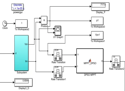
Fig 4. Simulation of DPSO under Uniform Irradiation.
Fig 5 Response of DPSO under Uniform Irradiation.
0 0.1 0.2 0.3 0.4 0.5 0.6 0.7 0.8 0.9 1
0 100 200 300 400 500 600 700 800
Time (Sec)
P
p
v
(
6
Fig 6. Response of DPSO under Uniform Irradiation for PV Curve.
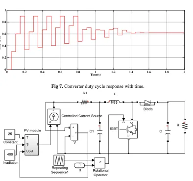
Fig 7. Converter duty cycle response with time.
Fig.8 Boost Converter in subsystem.
Sr. No
Parameter
Value.
1
Inductor
75μH
2
Capacitor
470μF
3
Switching frequency
20kHz
4
Load Resistance
24Ω
5
Resistance(R1)
0.01 Ω
6
Capacitor(C1)
2000μF
TABLE.1 Boost converter parameter.
0 10 20 30 40 50 60 70 80
0 100 200 300 400 500 600 700 800
Vpv (V)
Ppv
(W)
0 0.2 0.4 0.6 0.8 1 1.2 1.4 1.6 1.8 2
0 0.2 0.4 0.6 0.8 1
Time(s)
d
u
ty
c
y
cl
7 III.CONCLUSIONS
The DPSO method has been realized for uniform insolation with simulation. By sending three sets of duty cycle in the algorithm, neighborhood of MPP is achieved with fast response. By removing the random number and acceleration coefficients factors of the conventional PSO, the DPSO greatly simplifies the control structure of the MPPT. This method offers remarkable accuracy and speed compared to conventional HC.
ACKNOWLEDGMENT
This research is the result of many endless hours of hard work. It would not have been possible to complete without the help and supervision of many people. With a sense of gratitude and respect, I would like to extend my heartiest thanks to all those who provided help and guidance. I would like to articulate my profound gratitude and indebtedness to my guide Dr. Chirag A Naik who has always been a source of constant motivation and guiding factor throughout the course of the project, in and out as well
REFERENCES
[1] Kashif Ishaque and Zainal Salam “A Deterministic Particle Swarm Optimization Maximum Power Point Tracker for Photovoltaic System Under Partial Shading Condition ,” IEEE transaction on industrial electronics, VOL. 60, NO. 8,pp 3195 august 2013.
[2] K. Ishaque and Z. Salam, “An improved modeling method to determine the model parameters of photovoltaic (PV) modules using differential evolution (DE),” Solar Energy, vol. 85, no. 9, pp. 2349–2359, Sep. 2011.
[3] N.Pandiarajan,Rangananath Muthu, “Mathematical Modeling of Photovoltaic Module with Simulink,” International Conference on Electrical Energy Systems (ICEES), January 3-5,pp.314-319.
[4] K. Ishaque, Z. Salam, H. Taheri, and A. Shamsudin, “A critical evaluation of EA computational methods for Photovoltaic cell parameter extraction based on two diode model,” Solar Energy, vol. 85, no. 9, pp. 1768–1779, Sep. 2011.