Research Journal
Volume 11, Issue 2, June 2017, pages 172–179
DOI: 10.12913/22998624/70996 Research Article
INFLUENCE OF POST-PROCESSING ON THE ACCURACY
OF FDM PRODUCTS
Wiesław Kuczko1, Filip Górski1, Radosław Wichniarek1, Paweł Buń1
1 Poznan University of Technology, Chair of Production Engineering and Management, Poznan, Poland, e-mail: [email protected], [email protected], [email protected], pawel.bun@ put.poznan.pl
ABSTRACT
This paper presents the assessment of the rapid prototyping finishing techniques for printed components. The aim of the study was to compare the element printed with FDM technology before and after the treatment, using 3D scanning techniques. The object was scanned right after manufacturing, then it was subjected to finishing treat
-ment and 3D-scanned again. The assess-ment of the results was performed using the GOM Inspect software, based on a comparison between scans and nominal model.
Keywords: additive manufacturing, Fused Deposition Modelling, 3d scanning, post-processing, visual prototype.
INTRODUCTION
Additive Manufacturing Technologies (AMTs) are presently widely used in different branches of industry. They become a key tool allowing com
-panies to significantly shorten time of produc
-tion prepara-tion of a given product and, what follows, reduce the costs related to development and implementation of a new product into market. Among many advantages of AMTs, specific atten
-tion is paid to lack of the need of manufacturing dedicated tools, manufacturing directly on the ba
-sis of digital CAD model, wide range of available devices and used materials (ceramics, polymers, waxes, metals). What is more, thanks to additive, layered increase of material, it is often possible to discard entirely all processing limitations regard
-ing product shape complexity, which are present in traditional manufacturing technologies (ma
-chining, foundry, plastic processing) [19].
Among many AMTs, the Fused Deposition Modelling process is one of the most widespread and available for a wide group of users – in 2015 the machines realizing this process had 75% share in the market [10]. A reason for this state is
low cost of buying a machine in relation to other additive manufacturing processes, as well as non-complex and environmentally friendly process (materials are odorless and non-toxic, amount of waste is minimal, energy consumption is low). Among the most popular thermoplastic materials used in this process, ABS (Acrylonitrile-butadi
-ene-styrene) and PLA (Polylactic acid) must be mentioned in the first place, but a range of avail
-able materials is wide and still expanding [14]. Mechanical properties of products obtained us
-ing the FDM methods are strongly anisotropic [9, 7] but high enough for use in visual prototyping, mockups or design aids, or even functional prod
-ucts in some cases. That is why there are many potential application areas [6].
All the AMTs are characterized by building a product layer by layer in one direction, which causes inaccuracies in both dimensions and shape, mostly in a form of the so-called staircase effect. This defect is particularly well visible in the FDM technology. The effect is influenced by parameters of the manufacturing process (espe
-cially orientation of the product in the working chamber [8]), but it cannot be completely elimi
nated. For the visual quality oriented prototypes or when ergonomic or other factors cause the need of having a smooth surface, the staircase ef
-fect must be removed in post-processing.
Finished products are frequently fastened by means of adhesive joining technology [12]. A factor which is crucial to adhesive joint strength, particularly in bonding FDM-manufactured sub
-strates, is proper surface energy. Surface energy is determined by contact angle measurements using different probe liquids [11].
The paper presents an example of how post-processing can be performed in the FDM technol
-ogy, on an example of a particular visual proto
-type. The results of post-processing were evalu
-ated in geometrical terms – the authors made a 3D scan of the product before and after the post-processing, verifying the need for allowance as
-sumed in the CAD model, to ensure compatibility of the final geometry of the product with the nom
-inal geometry. Additionally, labor consumption of the surface finishing was assessed.
THEORETICAL INFORMATION
The staircase effect is related to a discrete di
-vision of an object into layers. In the FDM tech
-nology it is particularly visible and, especially for
curved edges and freeform surfaces, it heavily in
-fluences visual quality of the manufactured prod
-ucts. It is a main factor lowering dimensional and shape accuracy of 3D printed products. The prin
-ciple of the effect is illustrated in Fig. 1, where t stands for the layer thickness, ɛ - its translation and h – maximal deviation between surface of a digital model and a model manufactured in a 3D printing process [18].
The staircase effect is influenced mostly by layer thickness and product orientation in the working chamber of a FDM device [17]. The lower inclination of a product wall towards axis normal to a plane of the working table (greater translation of a layer), the more visible the effect is. It is the least visible for the right angle orienta
-tion (vertical walls). The effect is less influenced, but still affected by parameters such as thermo
-plastic material extrusion velocity [2] and mutual orientation of subsequent layers [1].
Many researchers have undertaken studies on possibility of limiting the effect by software means and increase of product accuracy by ap
-propriate modification of CAD model geom
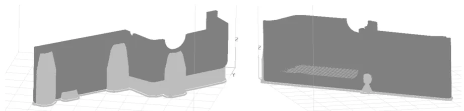
-etry [3] or optimization of product orientation in the working chamber [15]. However, in case of a complex shape, it is not possible to place a product in a way to minimize the effect on each wall. An example of such a product is a
Fig. 1. Staircase effect–principle and example [18]
prototype of a sink, presented in the paper, in which, regardless of the orientation, there will be at least one wall with the staircase effect clearly visible (Fig. 2).
In practice, limiting the staircase effect can be achieved by chemical coatings, which are ap
-plied to a product – they fill in the gaps between the “stairs”, creating a smooth surface. Many dif
-ferent materials can be used to that end, such as chemically hardened resins [13] and waxes [5].
Another method is use of CNC machining for post processing, which enforces planning certain allowances in a base CAD model and maintain
-ing appropriate minimum thickness of product walls, to prevent damage during the machining [4]. However, the most popular methods are sub
-jecting a product to a chemically aggressive agent and manual post-processing.
In the first case, the aggressive agent reacts with a thermoplastic material and causes flow (degradation) of the superficial shell layers, thus smoothing the external surface [16]. In case of the ABS material used commonly in the FDM processes, the chemical agent is technical ac
-etone. There are ready solutions available on the market, known as the smoothing stations, in which the whole smoothing process is car
-ried out automatically. There are also solutions of simplified design, which can be built manu
-ally on the basis of commonly available manu
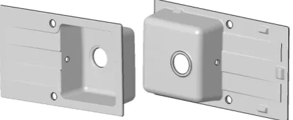
-factured goods. The only parameter changed by the user is time of exposure of a product for the vapors of the acetone. The greatest disadvantage of this method is rounding all the sharp edges, which leads to losing details in case of complex, intricate shapes (Fig. 3), that is why it is usu
-ally performed for visual prototypes of oval, or
-ganic shapes. Another disadvantage is related to work safety, as acetone is highly dangerous for humans and natural environment, especially in form of vapor.
In the second case of post-processing, manual tools for processing are used (precise files, sand paper of different gradations), as well as putties and priming paints. Advantages of this method are lack of a need of having additional devices at user’s disposal and a possibility of perform
-ing the process in a controlled way, maintain-ing sharp edges where needed. The main disadvan
-tage is labor consumption of the whole process and high susceptibility of its results to experience and skills of a person who is performing it.
PRACTICAL STUDIES
The product presented in the paper is a vi
-sual prototype of a kitchen sink originally made of conglomerate, scaled 1:3 comparing to the original size. The prototype was used as a visual tool for evaluation of shape and esthetics of a new line of products.
The product geometry was modeled in a CAD 3D software, then the solid was divided into two separately manufactured halves. It allowed short
-ening the manufacturing time and decrease of consumption of support material. Both halves were subjected to lossless conversion to the trian
-gular mesh format (STL). Shape of the product is presented in Fig. 4.
To manufacture the prototype, the authors used the Stratasys Dimension BST 1200 ma
-chine. As a build material of both halves, black acrylonitrile butadiene styrene (ABS) polymer material was used, with P400 designation by the producer, coming from one batch. For cal
-culation of the numerical code for the additive manufacturing machine, CatalystEX 4.1 soft
-ware was used. Layer thickness was assumed 0,254 mm, with solid (100%) infill of each layer. The support structures were calculated using the SMART algorithm available in the CatalystEX software, to minimize support vol
-ume. All the other process parameters were left
Fig. 3. Effect of smoothing a surface of ABS part with acetone vapors
at default values. Orientation of parts in the working chamber of the device are presented in Figure 5 (visible support structures).
Manufacturing of one half took 7,5 hours, with 88,66 cm3 of build material and 52,9 cm3 of
support material used. After the layer deposition process was finished, the products were taken out of the machine working chamber and left for cooldown to the ambient temperature (approx. 20°C) with the modelling tray on which they were manufactured, to avoid any possible thermal deformations. Then the parts were separated from the tray. The support structures were then removed and both halves were joined using cyanoacrylate adhesive. The object prepared in such a way was measured using GOM Atos Compact Scan 5M 3D optical scanner, using structured blue light for precise contactless measurement. Measuring field of 150 mm was used for the studies performed in the presented work. The obtained scan was a reference model for comparison with a scan of a product after the post-processing.
The next operation was the smoothing pro
-cess, which consisted in 5 stages presented in Fig. 6. Depending on the results obtained in a single iteration of this process, certain stages can be re
-peated, starting from the first stage (putty) or the third stage (painting).
Before the first application of putty, the whole surface of the product was preliminarily sanded with a water sand paper of gradation 240 and 320. The sanding was performed under water, to avoid scuffing of dust formed in the sanding process. After finishing the process, the product was thor
-oughly rinsed and dried in MCP FD240 furnace, in temperature of 35°C.
To fill large irregularities of the product sur
-face (especially in places where the staircase ef
-fect was formed), Novol Finish putty was applied. It is a finishing putty containing small grains of filler, which allow good deposition in thin layers and filling of small holes and crevices. It can be used for repairing small area surfaces and final smoothing between placing prime coats, it also allows grinding with fine-grained sand papers. Large advantage of this materials is also short time of drying, which is 30 minutes in temperature of 20°C, it can be shortened to 10 minutes if using a furnace of temperature not exceeding 40°C.
After the putty was hardened, the product was sanded with a sand paper of gradations: 120 (places where the highest amounts of putty were deposed), 320 and 500. After sanding and visual evaluation indicating another set of surface defects, putty was applied once again and sanding was repeated.
The stage of applying putty and sanding was repeated three times, eliminating all sur
-face defects visible to the naked eye. Then, after degreasing the product using the extraction naph
-tha, a priming paint was applied. Single compo
-nent acrylic filling priming paint Novol ACRYL PRIMER was used – it is meant for use mostly for evening up puttied surfaces. A big advantage of this primer is a possibility of applying a thick coat without risk of further fracturing, as well as short drying time – 15 minutes in ambient tem
-perature. The product was applied with two lay
-ers with a 20-minute break in between and then it was sanded under water with a sand paper of gra
-dation equal to 500. The priming paint very well fills small holes and crevices between ABS mate
-rial layers, which were left after the first sanding.
Fig. 5. Orientation of product (dark color) and support (bright color) in the working chamber of the 3D printer
After sanding and drying, the product was again subjected to visual evaluation. Grey color of the primer allows making this evaluation, as it brings out all the defects of the surface. It was necessary to again paint the product twice with the priming paint and sanding. After another visual evalua
-tion, which was positive, the product was sanded once again with a paper of gradation of 800 and
then 1500, before painting it with the final (deco
-rative) paint. A synthetic alkyd paint of general purpose Den Braven Super Color was applied, in black gloss color. After drying and degreasing the surface, one layer of paint was applied and the product was left for drying for another 90 min
-utes. This concluded the post-processing stage – the total time of this operation was 620 min
-Fig. 7. Product after puttying and sanding (left) and after putting priming paint
Fig. 8. Product after applying final decorative paint
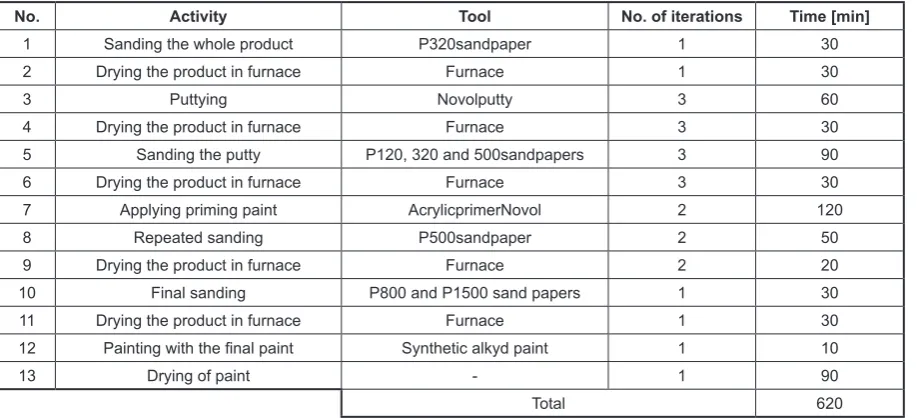
Table 1. Juxtaposition of times of particular stages of surface preparation
No. Activity Tool No. of iterations Time [min]
1 Sanding the whole product P320sandpaper 1 30
2 Drying the product in furnace Furnace 1 30
3 Puttying Novolputty 3 60
4 Drying the product in furnace Furnace 3 30
5 Sanding the putty P120, 320 and 500sandpapers 3 90
6 Drying the product in furnace Furnace 3 30
7 Applying priming paint AcrylicprimerNovol 2 120
8 Repeated sanding P500sandpaper 2 50
9 Drying the product in furnace Furnace 2 20
10 Final sanding P800 and P1500 sand papers 1 30
11 Drying the product in furnace Furnace 1 30
12 Painting with the final paint Synthetic alkyd paint 1 10
13 Drying of paint - 1 90
utes. The final product is presented in Fig 8. Jux
-taposition of times necessary for particular post-processing activities and number of iterations is presented in Table 1.
After the post processing, the product was again measured using the 3D scanner and com
-pared with the reference model, to determine de
-viations and estimate size of allowance, which should be planned in the CAD model. The com
-parative analysis was conducted in the GOM In
-spect V7 software, both scans were fitted using the
“best fit” algorithm. Average deviation was 0,185 mm. The results in a form of a colorful deviation map along with values of particular deviations in millimeters are shown in Figure 9 and 10.
RESULTS AND DISCUSSION
On the basis of comparison of both 3D scan
-ners, it can be observed that the largest deviations are present near corners of the product. To verify a
Fig. 9. Result of comparison (upper side) between 3D scan of a part before and after the post processing
reason for this, additional measurement was made – flatness error on the upper (visible for user) sur
-face of the product. In case of the reference model (without processing), the largest deviation was 0,6 mm and after the post processing it was 1,37 mm. Therefore, it must be stated that the flat part of the product was bent. It is the most likely caused by multiple heating in a furnace in temperature of 40°C, for acceleration of drying of the putty and drying the product before painting. As a result of increased temperature, thermal stresses cumulated in the material during the manufacturing were par
-tially released, what led to bending of thin-walled, flat fragment of the part of large surface area, the most susceptible to these stresses.
In case of surfaces, where the largest staircase effect was present (Figure 2), a deviation changing from the values close to 0 mm to value of approx. 0,2 mm, which is a size of a single “stair” mea
-sured on a reference 3D scan. The defects were filled using the putty, which allowed to make the product wall more close to a line present in Fig. 1, designated as a boundary of the STL model. Figure 11 presents superimposed cross-sections of both 3D scans. The staircase effect is clearly visible, as well as the final smooth surface.
In the other walls of the product no deviation exceeds 0,3 mm, while the walls where the stair
-case effect was minimal have even smaller devia
-tions, with dimensions close to the nominal values. There are also places with local increase of devia
-tions (up to 0,4 mm) in places, where the putty layer is too thick (it was not properly sanded).
CONCLUSIONS
The studies by the authors indicated, that smoothing products manufactured using the FDM method using various methods of post processing brings good results even in case of a very large staircase effect. Surface obtained as a result of these operations has proper quality, ensuring prop
-er visual effect, even aft-er applying black gloss paint which tends to emphasize all the surface de
-fects. An advantage is also a possibility of leaving sharp edges in required places and possibility of performing the post processing without addition
-al devices (common manu-al tools are sufficient). The applied chemical agents after drying are less dangerous for environment and ensuring minimal personal protection tools (latex gloves, protective glasses and mask with filter) prevents negative in
-fluence of these substances on the process operator. The main disadvantage of the process is its high labor consumption (620 minutes for the presented product, which is a very long time even in rela
-tion to time of 3D printing process itself), which can be reduced if more pieces are subjected to post processing at the same time, by parallel process
-ing and proper queu-ing. The final results are very much dependent on experience and manual skills of an operator (amount of iterations of particular tasks), which is why this process cannot be auto
-mated just as in the chemical smoothing stations. As results out of the conducted measurement analysis, there is no need for additional allowanc
-es. The material which is removed in the first sand
-ing is then replaced with a layer of a prim-ing paint. That is why differences between a raw FDM prod
-uct and a final prod-uct are not high. It is notewor
-thy, that in case of products manufactured using the FDM method, it is not advised to accelerate the drying process of putty or priming paint by heating in furnace. Depending on the product geometry, it may lead to its deformation. It is also important to use appropriate materials, meant for use with the polymer materials, what positively influences the total time of the process and the final result.
REFERENCES
1. Ahn D., et al.: Surface roughness prediction using measured data and interpolation in layered manu
-facturing. Journal of Materials Processing Tech
-nology, 209 (2), 2009, 664–671.
2. Anithaa R., et al. Critical parameters influencing the quality of prototypes in Fused Deposition Mod
-elling. Journal of Materials Processing Technolo
-gy, 118 (1), 2001, 385–388.
3. Boschetto A., et al. Design for manufacturing of surfaces to improve accuracy in Fused Deposi
-tion Modeling. Robotics and Computer-Integrated Manufacturing, 37, 2016, 103–114.
4. Boschetto A., et al. Finishing of Fused Deposi
-tion Modeling parts by CNC machining. Robot
-ics and Computer-Integrated Manufacturing, 41, 2016, 92–101.
5. Chil-Chyuan K., et al. A simple method for im
-proving surface quality of rapid prototype. Indian Journal of Engineering & Materials Sciences, 20, 2013, 465-470.
6. Fischer F. FDM and Polyjet 3D printing. Popular Plastics & Packaging, 60 (6), 2015, 31-34. 7. Gajdoš I., et al. Structure and tensile properties eval
-uation of samples produced by Fused Deposition Modeling. Open Engineering, 1 (6), 2016, 86-89. 8. Górski F., et al. Influence of process parameters on
dimensional accuracy of parts manufactured using Fused Deposition Modelling technology. Advanc
-es in Science and Technology R-esearch Journal, 7 (19), 2013, 27-35.
9. Górski F., et al. Strength of abs parts produced by Fused Deposition Modelling technology – a criti
-cal orientation problem. Advances in Science and Technology Research Journal, 9 (26), 2015, 12-19. 10. Greene T. U.S. 3D Printer Forecast, 2016–2020:
New 3D Print/Additive Manufacturing Technolo
-gies Fuel Growth. Whitehall Enterprises, Inc., 2016. 11. Kłonica M. and Kuczmaszewski J. Determining
the value of surface free energy on the basis of the contact angle:. Advances in Science and Technol
-ogy Research Journal, 11 (1), 2017, 66–74.
12. Kłonica M., et al. Polyamide 6 surface layer fol
-lowing ozone treatment. International Journal of Adhesion and Adhesives, 64, 2016, 179–187. 13. Kwang-Ho J., et al. A study of post-processing
methods for improving the tightness of a part fab
-ricated by fused deposition modeling. International Journal of Precision Engineering and Manufactur
-ing, 17 (11), 2016, 1541-1546.
14. Novakova-Marcincinova, L., et al. Special materi
-als used in FDM rapid prototyping technology ap
-plication. IEEE, 16th International Conference on Intelligent Engineering Systems (INES), Lisbon, Portugal 2012, 73-76.
15. Pennington R., et al. Significant factors in the di
-mensional accuracy of Fused Deposition Model
-ling. Proceedings of the Institution of Mechanical Engineers, Part E: Journal of Process Mechanical Engineering, 219 (1), 2005, 89-92.
16. Rupinder S., et al. Investigation for surface finish im
-provement of FDM parts by vapor smoothing process. Composites Part B: Engineering, 111, 2017, 228–234. 17. Vasudevarao B., et al. Sensitivity of RP surface fin
-ish to process parameter variation. Proceedings of solid free form fabrication, 2000, 252-258.
18. Weiss E., et al. Accuracy of parts manufactured by rapid prototyping technology. Annals of DAAAM for 2010 & Proceedings of the 21st In
-ternational DAAAM Symposium, Vienna, Aus
-tria 2010, 21, 1.
19. Wichniarek R., et al. Application of additively manufactured polymer composite prototypes in foundry. Advances in Science and Technology Re
![Fig. 1. Staircase effect–principle and example [18]](https://thumb-us.123doks.com/thumbv2/123dok_us/8807731.1775485/2.595.99.500.649.756/fig-staircase-effect-principle-and-example.webp)