ISSN: 2394-2231 http://www.ijctjournal.org Page 1
VOICE CONTROLLED ROBOT
K.Perachi Sangeetha,
Dr.A.Anitha
Dr.Ravi,
B.Tech-IV YEAR,
Professor
Professor & Head
Department of
Information
Technology,
Department of
Information
Technology,
Department of
Information
Technology,
Francis Xavier
Engineering College,
Francis Xavier
Engineering College,
Francis Xavier
Engineering College,
Tirunelveli,Tamilnadu
,India,
Tirunelveli,Tamilnadu
,India,
Tirunelveli,Tamilnadu
,India,
ABSTRACT-The research aims at designing a Robot which is controlled through Voice phone over Wi-Fi technology. The Robot can be moved in all the four directions (front, back, left and right) through predefined keys assigned in the voice application.The advent of new high-speed technology and the growing computer Capacity provided realistic opportunity for new robot controls and realization of new methods of control theory. This technical improvement together with the need for high performance robots created faster, more accurate and more intelligent robots using new robots control devices, new drivers and advanced control algorithms. This project describes a new economical solution of robot control systems. The presented robot arm control system can be used for different sophisticated robotic applications.The features are Wi-Fi based user-friendly interfacing,Usage of Voicephone’s Wi-Fi,Low power consumption.The proposed system are Regulated Power Supply,Arduino,Wi-Fi module,DC Motor with driver,Crystal oscillator,Reset,LED indicators.
I. INTRODUCTION
An embedded system is a system that has embedded software and computer-hardware which makes it a system dedicated for an application(s) or specific part of application or product or a part of a larger system.An embedded system is a system that has three main components embedded into it are It embeds hardware similar to a computer,It embeds main application software,It embeds a real-time operating system (RTOS).Embedded systems are controllers with on chip control. They consist of microcontrollers, input and output devices, memories etc., on chip
ISSN: 2394-2231 http://www.ijctjournal.org Page 2 systems are used for real time
applications with high reliability, accuracy and precision, embedded systems are operated with Real Time Operating systems like WinCE, RT Linux, VxWorks, PSOS, etc. Nowadays, embedded systems are very popular. Most of the Electrical, Electronics, Mechanical, Chemical, Industrial, Medical, Space and many more areas have the embedded systems in their applications.
A. Classifications
It can classify embedded systems into three types.They are Small scale embedded systems- These systems are designed with a single 8-bit or 16-bit microcontroller; they have little hardware and software complexities and involve board-level design. They may even be battery operated.Medium scale embedded systems-These systems are usually designed with a single or a few 16-bit or 32-bit microcontrollers, DSPs or RISCs. Medium scale embedded systems has both hardware and software complexities.Sophisticated embedded systems-These systems have enormous hardware and software complexities and may need several IPs, ASIPs, scalable processors or configurable processors and programmable logic arrays.
B. The Characteristics and constraints
An embedded system is characterized by the Real-time and multirate operations define the ways in which the, system works, reacts to events, and interrupts and schedules the system’s functioning
in real time. Complex
algorithm,Complex graphic user interfaces (GUIs) and other user interfaces,Dedicated functions.An embedded system is designed keeping in
view three constraints are Available system memory,Available processor speed,The need to limit power dissipation when running the system continuously in cycles of ‘wait for events’, ‘run’, ’stop’, ’wake up’ and ‘sleep’.The Applications of Embedded Systems are Robotics,Aviation
Telecommunication and
Broadcasting,Mobile Phones and mobiles networking, Satellite Communication,Blue Tooth, Electronic sensors, Home Appliances etc.
ISSN: 2394-2231 http://www.ijctjournal.org Page 3 non-verbal voice controlled robotics and
prosthetic limbs will be successful.[2]. The aim of the proposed paper robotic furniture system provides an integrated solution, comprising reduced space utilization, modularity, and intelligent operation while maintaining ergonomy. A set of electrical motors is used to position the various sections of the system into the correct height level, and to displace them towards the horizontal axis, to allow a rotational motion path. A vision system was integrated on the prototype to perform object recognition, in order to efficiently classify objects stored into the various system sections, and in order to assist the user in retrieving a specific previously stored object, by moving the appropriate section of the furniture into the correct height.[3].
III. Proposed System Block diagram:
Fig. 1.Block diagram A. POWER SUPPLY
This circuit is worn to renovate the AC to DC. It restrains of step down transformer, bridge rectifier, ripple filter, voltage regulator and line filter. Rationale of transformer is to step down the 230 VAC to 15VAC. This AC
voltage is auxiliary rectified using bridge rectifier, the productivity of bridge rectifier is pulsating DC with small AC ripples. This AC ripples are then filtered using 1000uF shunt capacitor. Because the capacitor grounds AC signal and evade the DC, so the output across the shunt capacitor is pure DC. This DC voltage is unfettered, because change in primary of the transformer will change this DC voltage. So it needs to regulate the voltage. Here it use series voltage regulator is used to regulate the voltage. At last one 10uF shunt capacitor is used to filter the fluctuation due to switching of SCR’s.
ISSN: 2394-2231 http://www.ijctjournal.org Page 4 The LM7805 series of
three terminal regulators is available with several fixed output voltages making them useful in a wide range of applications. One of these is local on card regulation, eliminating the distribution problems associated with single point regulation. The voltages available allow these regulators to be used in logic systems, instrumentation, HiFi, and other solid state electronic equipment. Although designed primarily as fixed voltage regulators these devices can be used with external components to obtain adjustable voltages and currents .
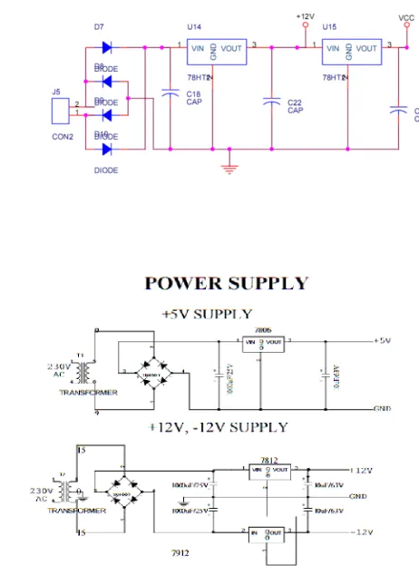
B. CIRCUIT DESCRIPTION 1) POWER SUPPLY:
Here in this project most of the operations are operated in 5V and 12V. So it use 230V/12V potential transformer and 7805 regulator for 5V. Power supply circuit consists of bridge rectifier, ripple filter, regulator and line filter. Bridge rectifier is constructed using 1N4007 diode. Ripple filter is build around 1000uF/25V.
2) POWERSUPPLY SECTION
Types of Power Supply:There are many types of power supply. Most are designed to convert high voltage AC mains electricity to a suitable low voltage supply for electronics circuits and other devices. A power supply can by broken down into a series of blocks, each of which performs a particular function.For example a 5V regulated supply:
Fig .3.Regulated power supply system
Transformer - steps down high voltage AC mains to low voltage AC.Rectifier - converts AC to DC, but the DC output is varying.Smoothing - smooths the DC from varying greatly to a small ripple.Regulator - eliminates ripple by setting DC output to a fixed voltage.
Power supplies made from these blocks are described below with a circuit diagram and a graph of their output:
1. Transformer only
2. Transformer + Rectifier
3. TransforTransformer onlymer + Rectifier + Smoothing
Transformer + Rectifier + Smoothing + Regulator Transformer only
Fig .4. Transformer
The low voltage AC output is suitable for lamps, heaters and special AC motors. It is not suitable for electronic circuits unless they include a rectifier and a smoothing capacitor.
ISSN: 2394-2231 http://www.ijctjournal.org Page 5 The varying DC output is suitable for
lamps, heaters and standard motors. It is not suitable for electronic circuits unless they include a smoothing capacitor.
Further information:
Fig .6.
Transformer + Rectifier + Smoothing
The smooth DC output has a small ripple. It is suitable for most electronic circuits.
Transformer | Rectifier | Smoothing Transformer + Rectifier + Smoothing + Regulator
Fig.7.
Transformer | Rectifier | Smoothing |Regulator
The regulated DC output is very smooth with no ripple. It is suitable for all electronic circuits.Transformers convert AC electricity from one voltage to another with little loss of power. Transformers work only with AC and this is one of the reasons why mains electricity is AC.Step-up transformers increase voltage, step-down transformers reduce voltage. Most power supplies use a step-down transformer to reduce the dangerously high mains voltage (230V in UK) to a safer low voltage.The input
coil is called the primary and the output coil is called the secondary. There is no electrical connection between the two coils, instead they are linked by an alternating magnetic field created in the soft-iron core of the transformer. The two lines in the middle of the circuit symbol represent the core.Transformers waste very little power so the power out is (almost) equal to the power in. Note that as voltage is stepped down current is stepped up.The ratio of the number of turns on each coil, called the turns ratio, determines the ratio of the voltages. A step-down transformer has a large number of turns on its primary (input) coil which is connected to the high voltage mains supply, and a small number of turns on its secondary (output) coil to give a low output voltage.
turns ratio = V p
= N p
And
power out = power in
Vs Ns Vs × Is = V p × I p
Vs = secondary (output) voltage Ns = number of turns on secondary coil I s = secondary (output) current
ISSN: 2394-2231 http://www.ijctjournal.org Page 6 Fig .8.Transformer circuit symbol
Fig .9.Rectifier
There are several ways of connecting diodes to make a rectifier to convert AC to DC. The bridge rectifier is the most important and it produces
Full-wave varying DC. A full-wave rectifier can also be made from just two diodes if a centre-tap transformer is used, but this method is rarely used now that diodes are cheaper. A single diode can be used as a rectifier but it only uses the positive (+) parts of the AC wave to produce half-wave varying DC.
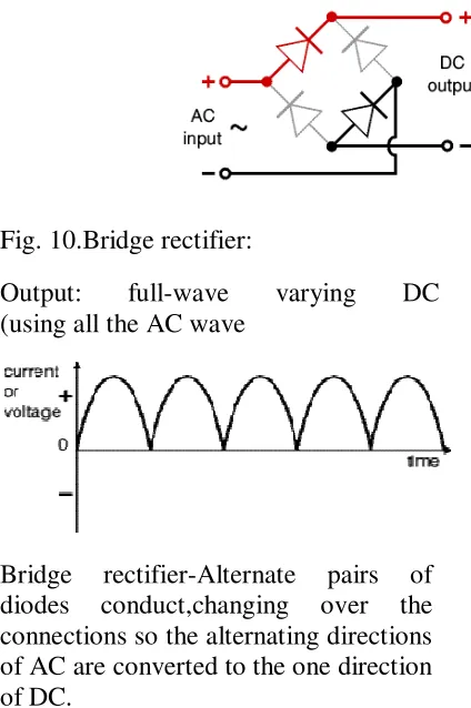
Bridge rectifier:A bridge rectifier can be made using four individual diodes, but it is also available in special packages containing the four diodes required. It is called a full-wave rectifier because it uses all the AC wave (both positive and negative sections). 1.4V is used up in the bridge rectifier because each diode uses 0.7V when conducting and there are always two diodes conducting, as shown in the diagram below. Bridge rectifiers are rated by the maximum current they can pass and the maximum reverse voltage they can withstand (this must be at least three times the supply RMS voltage so the rectifier can withstand the peak voltages). Please see the Diodes page for more details, including pictures of bridge rectifiers.
Fig. 10.Bridge rectifier:
Output: full-wave varying DC (using all the AC wave
Bridge rectifier-Alternate pairs of diodes conduct,changing over the connections so the alternating directions of AC are converted to the one direction of DC.
ISSN: 2394-2231 http://www.ijctjournal.org Page 7 Single diode rectifier:
A single diode can be used as a rectifier but this produces half-wave varying DC which has gaps when the AC is negative. It is hard to smooth this sufficiently well to supply electronic circuits unless they require a very small current so the smoothing capacitor does not significantly discharge during the gaps. Please see the Diodes page for some examples of rectifier diodes.
Single diode rectifier
Output: half-wave
varying DC
(using only half the AC wave)
Smoothing-Smoothing is performed by a large value electrolytic capacitor connected across the DC supply to act as a reservoir, supplying current to the output when the varying DC voltage from the rectifier is falling. The diagram shows the unsmoothed varying DC (dotted line) and the smoothed DC (solid line). The capacitor charges quickly near the peak of the varying DC, and then discharges as it supplies current to the output.
C. ARDUINO
Arduino is a computer hardware and software company, project, and user community that designs and manufactures microcontroller kits for building digital devices and interactive objects that can sense and control objects in the physical world. The project's products are distributed as open-source hardware and software, which are
licensed under the GNU Lesser General Public License (LGPL) or the GNU General Public License (GPL), [1]
permitting the manufacture of Arduino boards and software distribution by anyone. Arduino boards are available commercially in preassembled form, or as do-it-yourself kits. Arduino is open-source hardware. The hardware reference designs are distributed under a Creative Commons Attribution Share-Alike 2.5 license and are available on the Arduino website. Layout and production files for some versions of the hardware are also available. The source code for the IDE is released under the GNU General Public License, version 2.[8]Nevertheless an official Bill of Materials of Arduino boards has never been released by the staff of Arduino. An Arduino board consists of an Atmel 8-, 16- or 32-bit AVR microcontroller (ATmega8,
ATmega168, ATmega328,
ISSN: 2394-2231 http://www.ijctjournal.org Page 8 languages Processing and Wiring. It was
created for people with no profound knowledge of electronics. It includes a code editor with features such as syntax highlighting, brace matching, cutting-pasting and searching-replacing text, and automatic indenting, and provides simple one-click mechanism to compile and upload programs to an Arduino board. It also contains a message area, a text console, a toolbar with buttons for common functions and a series of menus. A program written with the IDE for Arduino is called a "sketch".[40]Sketches are saved on the development computer as files with the file extension .ino. Arduino Software (IDE) pre-1.0 saved sketches with the extension .pde. The Arduino IDE supports the languages C and C++ using special rules to organize code. The Arduino IDE supplies a software library from the Wiring project, which provides many common input and output procedures. User-written code only requires two functions, for starting the sketch and the main programs loop, that are compiled and linked with a program stub main() into an executable cyclic executive program with the GNU toolchain, also included with the IDE distribution. The Arduino IDE employs the program avrdude to convert the executable code into a text file in hexadecimal coding that is loaded into the Arduino board by a loader program in the board's firmware.
MAX232
The MAX232 is a dual driver/receiver that includes a capacitive voltage generator to supply TIA/EIA-232-Fvoltage levels from a single 5-V supply. Each receiver converts TIA/EIA-232-F inputs to 5-V TTL/CMOS levels .These receivers have a typical threshold
of 1.3 V, a typical hysteresis of 0.5 V, and can accept ±30-V inputs .Each driver converts TTL/CMOS input levels into TIA/EIA-232-F levels. The driver, receiver, and voltage-generator functions are available as cells in the Texas Instruments LinASIC library
CIRCUIT DIAGRAM
Figure. 11.Circuit diagram of MAX-232 Level converter
D. Wi-Fi
Wi-Fi or WiFi is a technology for wireless local area networking with devices based on the IEEE 802.11 standards. Wi-Fi is a trademark of the Wi-Fi Alliance, which restricts the use of the term Wi-Fi Certified to
products that successfully complete interoperability certification
ISSN: 2394-2231 http://www.ijctjournal.org Page 9 20 meters (66 feet) indoors and a greater
range outdoors. Hotspot coverage can be as small as a single room with walls that block radio waves, or as large as many square kilometres achieved by using multiple overlapping access points.
Fig.12.Wi-Fi
IV. Experiment Result:
Crystal Impedance against Frequency
The slope of the crystals impedance above shows that as the frequency increases across its terminals. At a particular frequency, the interaction of between the series capacitor Cs and the inductor Ls creates a series resonance circuit reducing the crystals impedance to a minimum and equal to Rs. This frequency point is called the crystals series resonant frequency ƒs and below ƒsthe crystal is capacitive.As the frequency increases above this series resonance point, the crystal behaves like an inductor until the frequency reaches its parallel resonant frequency ƒp. At this frequency point the interaction between the series inductor, Ls and
parallel capacitor, Cp creates a parallel tuned LC tank circuit and as such the impedance across the crystal reaches its maximum value.Then it can see that a quartz crystal is a combination of a series and parallel tuned resonance circuits, oscillating at two different frequencies with the very small difference between the two depending upon the cut of the crystal. Also, since the crystal can operate at either its series or parallel resonance frequencies, a crystal oscillator circuit needs to be tuned to one or the other frequency as you cannot use both together. So depending upon the circuit characteristics, a quartz crystal can act as either a capacitor, an inductor, a series resonance circuit or as a parallel resonance circuit and to demonstrate this more clearly, it can also plot the crystals reactance against frequency as shown.Series Resonant Frequency
The parallel resonance
frequency, ƒp occurs when the reactance of the series LC leg equals the reactance of the parallel capacitor, Cp and is given as:Parallel Resonant Frequency
ISSN: 2394-2231 http://www.ijctjournal.org Page 10 frequency.The crystals series resonant
frequency, ƒS
The crystals parallel resonant frequency, ƒP
It can see that the difference between ƒs, the crystals fundamental frequency and ƒp is small at about 18kHz (10.005MHz – 9.987MHz). However during this frequency range, the Q-factor (Quality Factor) of the crystal is extremely high because the inductance of the crystal is much higher than its capacitive or resistive values. The Q-factor of our crystal at the series resonance frequency is given as:Crystal Oscillators Q-factor
References:
http://ieeexplore.ieee.org/abstract/docum ent/1546363/?reload=true
http://dl.acm.org/citation.cfm?id=1518731
http://www.sciencedirect.com/science/arti cle/pii/S0926580513001076
http://www.edgefxkits.com/voice-controlled-robotic-vehicle
https://www.engineersgarage.com/contri bution/android-based-voice-controlled-robot