Available Online at www.ijpret.com 1
INTERNATIONAL JOURNAL OF PURE AND
APPLIED RESEARCH IN ENGINEERING AND
TECHNOLOGY
A PATH FOR HORIZING YOUR INNOVATIVE WORK
EXPERIMENTAL INVESTIGATION OF REINFORCEMENT COUPLERS AS
REPLACEMENT OF BENT BAR
ROHITKUMAR A. PANDEY1, CHIRAG N. PATEL2
1. PG Student, Department of Civil Engineering, SAL Institute of Technology and Engineering Research, Ahmedabad, Gujarat, India - 380060 2. Assistant Professor Department of Applied Mechanics, Government Engineering College, Modasa, Gujrat, India – 383315
Accepted Date: 22/05/2018; Published Date: 01/06/2018
\
Abstract: - In reinforced concrete structures, it is essential to enhance the performance of beam–column joints in moderate and severe seismic susceptibility areas. An attempt has been made to study and evaluate the performance of exterior beam–column joint using proper reinforcement anchorage and joint core detail. The anchorages are detailed as per ACI-352 (Mechanical anchorage), ACI-318 (900Standard bent anchorages) and IS-456 along with confinement as per IS-13920. Significant improvements were observed in seismic performance, ductility and strength while using stirrups bar in combination with mechanical anchorage detail for higher seismic prone areas, apart from resolution to reducing congestion of reinforcement in joint core. To assess the performances of anchorages and joint details, three groups of three specimens each were tested under monolithic loading. The test results are evaluated and presented in this paper.
Keywords: Anchorage Bar, Beam Column Joint, reinforced concrete, T-type anchorage, Mechanical anchorage
Corresponding Author: ROHITKUMAR A. PANDEY Access Online On:
www.ijpret.com
How to Cite This Article:
Available Online at www.ijpret.com 2
INTRODUCTION
Many reinforced concrete (RC) buildings, such as non-ductile RC frames, designed during the 1950s through 1970s existing today in many parts of the world do not satisfy the current seismic design requirements. These buildings generally do not possess adequate ductility due to poor detailing of reinforcement. Observations made on the failures of the existing structures due to earthquakes reveal that strengthening or retrofitting is necessary due to (i) Poor detailing of joint reinforcement, (ii) Deficient materials and inadequate anchorage length of beam reinforcement, (iii) Improper confinement of joint region by transverse reinforcements, (iv) Changes in the current design detailing requirement and (v) changes of loads due to frequency of earthquakes and alterations of earthquake zones. The failure of beam-column joints is the major contributor for the collapse of buildings due to earthquake excitation. It establishes the need for engineering approach to adopt efficient and economical methods to improve the joint performance. The need for study of earthquake effects on structures was realized when earthquakes occurred through the 1960s and 1970s causing irreparable damage and human loss. The design of joints was not given importance in the framed structures designed for gravity loads or gravity and routine live loads only. This causes severe problem in the event of an earthquake. Several studies led to the development of ASCE-ACI 352 Committee. Recommendations for the design of reinforced concrete beam-column joints (connections) in the year 1976. But there is a lot that has still not been understood about beam-column joint and research needs to highlight these issues [9].
In reinforced concrete structures, the detailing problems related to the anchorage of reinforcement bars are often of great importance due to the long development lengths and large bend radius required for straight or hooked bars [10]. Alternatives to conventional detailing not so common in ordinary structures but with a long history in heavily reinforced structures have been developed since the middle of the 20th century [10]. Known as mechanical anchorages, they are particularly useful in presence of large bar diameters, because they can achieve the anchorage by a combination of development length and a plate anchor that can be fixed to the rebar contributing to the total anchorage capacity. Therefore, the use of plate-anchored reinforcement bars reduces the development length needed and simplifies the detailing of congested areas, also reducing significantly the placing times.
Available Online at www.ijpret.com 3
devices can be used, but they frequently require special construction skill and careful attention to tolerances.
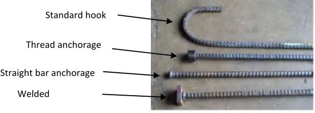
Mechanical anchorage, as shown in Fig 1, provide an alternative to hooked bars and assist in alleviating steel congestion. Previous research on mechanical anchorage may be divided into two categories: performance of mechanical anchorage in realistic structural systems, and investigation of the mechanics of the mechanical anchorage under idealized conditions. Previous structural system studies include a number of beam-column joint investigations, where mechanical anchorage were used for longitudinal reinforcement, and slab-column joint investigations, where mechanical anchorage were used for shear reinforcement. The reliability and applicability of the mechanical anchorage were validated in these studies and, consequently, guidelines on the use of mechanical anchorage were introduced in ACI 352R-028[11] and ACI 421.1R-08. These guidelines provide guidance on general application of bars but do not provide direct estimates for the anchorage strength of mechanical anchorage.
Figure 1: Standard hook & Various mechanical anchorage (#8 size)
Reinforcement coupler requirements for the beam longitudinal reinforcement bar and the joint confinement are the main issues related to problems of congestion of reinforcement in the beam–column connections. An attempt has been made to evaluate the performance of the exterior beam–column joint by replacing the 900 standard bent bar anchorages by mechanical anchorage and additional stirrups in the exterior beam–column joint core for the moderate and severe seismic prone zones. The seismic zones are followed as per IS-1893 and IS-13920 (2016). It is found that these combinations were effective in reducing the congestion of reinforcement in joint core and eased pouring of concrete without compromising the ductility and stiffness of beam–column joints under monolithic loading.
Standard hook
Thread anchorage
Straight bar anchorage
Available Online at www.ijpret.com 4
MATERIAL PROPERTIES USED
Concrete was made with 53 grade cement with sand and 20 mm coarse aggregate. The quantities of material per cubic meter of concrete used were; cement = 600 kg/m3, fine aggregate = 826.774 kg/m3, coarse aggregate= 1578.22 kg/m3, water = 315.6 kg/m3, water/cement ratio= 0.5 and the 28th day average cube compressive strength was 31.5 MPa. The reinforcement bars used were 8mm diameter, all of HYSD steel of grade Fe-415 (fy = 415 N/mm2) the grade of headed bar used was E410 (Fe-540) with yield strength of 410 MPa.
TESTING PROGRAM
The specimens are divided into three groups, each group comprising three specimens, with different reinforcement coupler. The reinforcement coupler details of specimens are designated as A, B and C and joint details designated as 1 and 2&3. The specimen with headed bar followed as per ACI-352 (2002) is designated as detail-A, the specimen with conventional 90◦ bent hook followed as per ACI-318 (2011) is designated as detail-B and the specimen with full anchorage followed as per IS-456 (2000) is designated as detail-C. The joint core of the specimen without confinement reinforcement is designated as joint and the joint core of the specimen with additional stirrup is designated as joint detail.
EXPRIMENTAL TEST SETUP
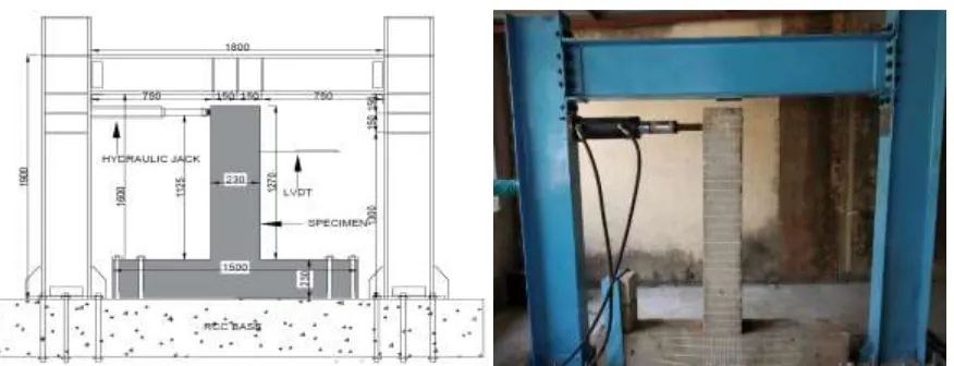
The half-scale exterior beam-column joint specimen testing was carried out at, Government Engineering College, Modasa, Gujrat, INDIA. The joint assemblage was subjected to monolithic loading using of 25 ton (250 kN) capacity hydraulic jacks. The specimen was oriented as described below.
Available Online at www.ijpret.com 5
DETAILS OF TEST SPECIMENS
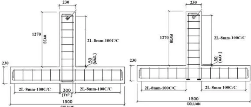
All the specimens were identical in size and the beam sizes were 200 mm × 230 mm and cross section of the column were 230 mm × 200 mm as shown in figure 3. The length of the beam was 1270 mm from the column face and the height of the column was 1500 mm. The various types of anchorages used has been shown in figures and the joint details used has been shown in fig 4. In group-I, the anchorages A, B and C were combined with joint detail-1 and these specimens were named as A1, B1and C1. Similarly, in group-II & III, the anchorages A, B and C were combined with joint detail-2 and these specimens were named as A2,A3, B2.B3 and C2,C3.
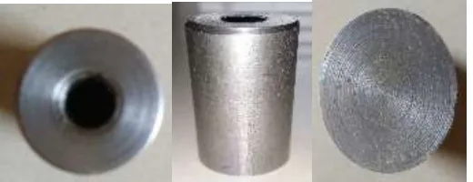
Figure 2 Reinforcement coupler
.
Available Online at www.ijpret.com 6
Type A Type B
Type C
Available Online at www.ijpret.com 7
Figure 5: Schematic diagram of test setup Figure 6: Filed arrangement of test setup
OBTAINED RESULT
Specimen Type
Yielding displacement in mm (∆y)
Ultimate load in KN (Pu)
displacement for ultimate load(∆u)
displacement ductility factor µ=∆u/∆y
stiffness KN/mm k=Pu/∆y
Type A
(conventional)
A1 2.15 83.81 68.00 31.63 38.98
A2 2.40 87.07 72.00 30.00 36.28
A3 2.20 89.40 74.00 33.64 40.64
Type B
(Coupler)
B1 2.30 88.47 50.00 21.74 38.47
B2 2.85 93.13 53.00 18.60 32.68
B3 3.00 97.78 55.00 18.33 32.59
Type C (coupler with stirrups)
C1 3.15 97.78 45.00 14.29 31.04
C2 3.20 100.11 48.00 15.00 31.28
C3 3.25 102.44 50.00 15.38 31.52
Available Online at www.ijpret.com 8
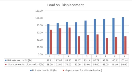
Figure 7 : Observed yield load, ultimate load ductility and Stiffness test
Figure 8: Load Vs. Displacement 0.00
20.00 40.00 60.00 80.00 100.00 120.00
A1 A2 A3 B1 B2 B3 C1 C2 C3
Type A (conventional) Type B (Coupler) Type C (coupler with stirrups)
Yielding displacement in mm (∆y) Ultimate load in KN (Pu)
displacement for ultimate load(∆u) displacement ductility factor µ=∆u/∆y
stiffness KN/mm k=Pu/∆y
1 2 3 4 5 6 7 8 9
Ultimate load in KN (Pu) 83.81 87.07 89.40 88.47 93.13 97.78 97.78 100.11 102.44
displacement for ultimate load(∆u) 68.00 72.00 74.00 50.00 53.00 55.00 45.00 48.00 50.00
0.00 20.00 40.00 60.00 80.00 100.00 120.00
Load Vs. Displacement
Available Online at www.ijpret.com 9
CRACK PATTERN STUDY
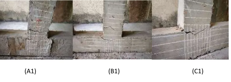
The anchorages and joint details of specimens A1, B1 and C1 are shown in Fig 9, respectively. It can be seen from Fig. 9, shear cracks have developed on the beam-column junction in all the specimens where the plastic hinge formed at the face of the column. Further, diagonal cracks have also developed in the column shear panel area of the specimens B1 and C1. Besides the wide-open cracks in the junction, the concrete had also spilled out from the specimens B1 and A1. In Group-I, the specimen with mechanical anchorage with stirrups (C1) shows the lesser cracks and much better control of crack capacity than the other specimens. It can therefore be concluded that these types of joint core details are much more effective in controlling beam-column joint than conventional joints. It is apparent that the use of mechanical anchored bars is a viable alternative to use of standard 900 hooks in exterior beam-column joints in combination with the moderate and higher seismic prone area.
(A1) (B1) (C1)
Figure 9: Crack pattern of Group-1 (A1, B1, & C1)
Available Online at www.ijpret.com 10
(A2) (B2) (C2)
Figure 10: Crack pattern of Group-2 (A2, B2, & C2)
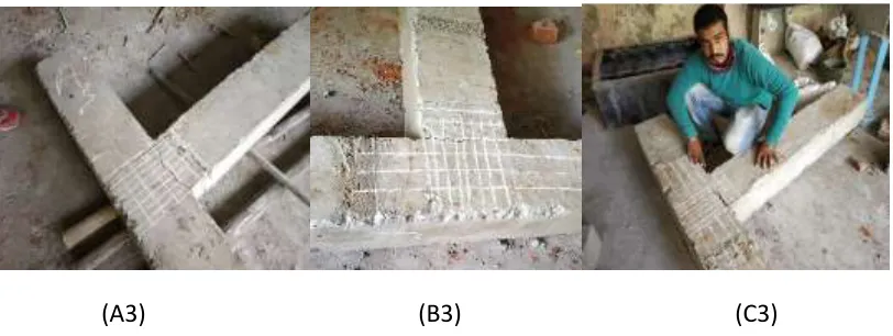
The anchorages and joint details of specimens A3, B3 and C3 are shown in Fig 11, respectively. It can be seen from Fig. 11 that shear cracks have developed in the beam-column junction and diagonal cracks have developed in the column shear panel area of all the specimens and the wide-open crack pattern can be observed. In addition, the concrete had spilled out from the specimens B3 and A3 with buckling of beam longitudinal reinforcement. In Group-3, specimen C3 (mechanical anchorage) has the lesser crack pattern with only a few diagonal cracks were formed at joint core than specimens B3 and A3.
(A3) (B3) (C3)
Figure 11: Crack pattern of Group-3 (A3, B3, & C3)
Available Online at www.ijpret.com 11
joint shear panel area. The specimens C1 and C2 & C3 with mechanical anchorage shows a lesser crack pattern than other specimens using conventional joints details in Group-I and II & III without losing the strength, however, specimen C1 with mechanical anchorage in combination with stirrup, shows lesser cracks and much better control of crack capacity than other specimens. The X-cross bar is provided to control tensile failure in concrete of the joint shear panel area due to strut and tie action. Stranded conventional shear links are replaced with U-bar for easier fabrication. It can therefore be concluded that mechanical (headed U-bar) types of anchorages with proposed joint core details are much more effective in controlling beam column joint. It is apparent that the use of mechanical anchored bars is a viable alternative to use of standard 900 hooks in exterior beam-column joints in seismic prone area. In addition, it effectively reduces the reinforcement congestion and is easier to repair using FRP composite wraps techniques to restore the flexural strength.
CONCLUSION
The loading condition (monotonic), head shape (circular), and head-attaching techniques (threading) did not influences the anchorage behavior substantially during testing.
It has been observed from the experimental test results that the Reinforcement Coupler as per ACI-352 (specimens A1 and A2,A3) offer better performance than the specimens reinforced with conventional 900 standard bent hooks anchorage as per ACI-318(specimens B1and B2,B3) and full anchorage as per IS-456(specimens C1and C2,C3). In addition, significant improvement in the ductility was observed in that Group-I exhibit higher ductility than Group-II & III specimens A3, B3 and C3 by 10.70%,36.97% and 20.58% respectively.
The specimen B1 and B2,B3 with mechanical anchorage shows lesser crack pattern than other specimens using conventional anchorage and joint details.
The use of a single mechanical anchorage device in place of the 90-degree hook terminating in the joint resulted in an equivalent or better performance under large inelastic displacement.
Mechanical anchorage joint detail offers a better moment carrying capacity thereby improving the seismic performance without compromising the ductility and stiffness.
Available Online at www.ijpret.com 12
in the joint core area. The mechanical anchored bar is a viable alternative to the use of conventional 900 bent hook anchorages.
REFERENCES
1. John w. Wallace, Scott w. McConnell “use of mechanically anchored bars in exterior beam-column joints subjected to subjected to seismic loads” Erico inc., solon, ohio- 1997
2. Wallace, J.W., McConnell, S.W., Gupta, P., Cote, P.A., 1998. Used of headed reinforcement in beam–column joints subjected to earthquake loads. ACI Structural Journal 95 (5), 590–606. 3. Kang TH-K. Recommendations for design of RC beam-column connections with mechanical anchorage subjected to cyclic loading. The 14th world conference on earthquake engineering (14WCEE), Beijing, China (Paper No. 08–01-0017); 2008b.
4. Kang, T. H.-K.; Ha, S.-S.; and Choi, D.-U., “Seismic Assessment of Beam-to Column Interactions Utilizing Mechanical anchorage,” Proceedings of the 14WCEE, Beijing, China, Oct. 2008, 8 pp. (Paper No. 05-03-0047).
5. Lee, H.-J., Yu, Si-Ying, 2009. Cyclic response of exterior beam–column joints with different Anchorage methods. ACI Structural Journal 106 (3), 329–339.
6. Kang, T.H.-K., Shin, M., Mitra, N., Bonacci, J.F., 2009. Seismic design of reinforced concrete beam–column joints with mechanical anchorage. ACI Structural Journal 106 (6), 868–877. 7. Thomas H.-K. Kang, Nilanjan Mitra “Prediction of performance of exterior beam-column connections with mechanical anchorage subject to load reversal” Engineering Structures – April 2012
8. S. Rajagopal, S. Prabavathy, “Investigation on the seismic behavior of exterior beam–column joint using T-type mechanical anchorage with hair-clip bar” Journal of King Saud University “Engineering Sciences” - September 2013
9. Vaibhav R. Pawar, Dr. Y.D.Patil, Dr. H.S.Patil “Cyclic loading of Exterior Beam - Column Joint with Threaded headed Reinforcement” International Journal of Applied Engineering – 2017 10. Francesco marchetto “Use Of Headed Reinforcement Bars In Construction” April 8, 2015. http://www.he-upm.com
11. ACI Committee 318 (2014). Building code requirements for structural concrete (ACI 318-14) and commentary (318R-14). Farmington Hills, Mich., U.S.A.
12. Joint ACI-ASCE Committee 352 (2002). Recommendations for design of beam-column connections in monolithic reinforced concrete structures (ACI 352R-02). Farmington Hills, Mich., U.S.A.
Available Online at www.ijpret.com 13