Available Online at www.ijpret.com 11
INTERNATIONAL JOURNAL OF PURE AND
APPLIED RESEARCH IN ENGINEERING AND
TECHNOLOGY
A PATH FOR HORIZING YOUR INNOVATIVE WORK
STUDY OF EFFECT ON OPERATING PARAMETERS OF SHELL AND TUBE HEAT
EXCHANGER USING CHEMCAD
DR. SAMEER M. WAGH, DIVYA P. BARAI, MEGHA H. TALWEKAR
Laxminarayan Institute of Technology, Rashtrasant Tukadoji Maharaj Nagpur University, Nagpur
Accepted Date: 04/05/2016; Published Date: 01/08/2016
\
Abstract: - Computer-aided design has become extremely popular as it assists in the creation, modification, analysis, or optimization of design of any equipment. It is also used to simulate the material and energy balances of chemical processing plants. Software’s such as Aspen HYSYS, CHEMCAD, Aspen Plus, HTRI Xchanger Suite etc. are mainly used for the study of effects of the many interacting design parameters and achieve an optimum thermal design. Shell and tube heat exchangers are used extensively throughout the process industry and their optimum thermal design involves the consideration of many interacting design parameters. Some of the parameters affecting the overall performance of a shell and tube heat exchanger are the pressure drop across the exchanger, the velocity of the fluids, the film coefficients, effective heat transfer area etc. Pressure drop is a parameter which is always strived to be kept minimum for the optimal design of heat exchangers. Also, the velocity of the fluids and the film coefficient which are dependent on each other are to be studied during heat exchanger designing. The change in all these parameters is studied by performing variations in the design of the heat exchanger. The variations performed include different values for number of tube passes, outer diameter of tubes and inner diameter of shell. Thus, results indicated that the pressure drop in the shell side increases with increase in outer diameter of tube and decreases with increase in inner diameter of shell. And in the tube side, the pressure drop increases with increase in number of tube passes. Also, the average velocity of the shell side increases with increase in outer diameter of tube and decreases with increase in inner diameter of shell. And average velocity of the tube side fluid increases with increase in number of tube passes. The film coefficients also show a specific change in their value.
Keywords: CHEMCAD, Heat Exchanger, Parameters
Corresponding Author: DR. SAMEER M. WAGH
Access Online On:
www.ijpret.com
How to Cite This Article:
Available Online at www.ijpret.com 12
1. INTRODUCTION
The use of information technology in the design process is called as computer-aided design (CAD). The core of a CAD system is the software, which makes use of graphics for product representation, databases for storing the product model and drives the peripherals for product presentation. The user can perform Static, Dynamic and Natural Frequency analysis, Heat transfer analysis, Plastic analysis, Fluid flow analysis, Motion analysis, Tolerance analysis, Design optimization etc. on such systems (Bilalis, 2000). CAD systems can shorten the design time of a product. Softwares providing such facilities include Aspen HYSYS, CHEMCAD, Aspen Plus, HTRI Xchanger Suite etc.
CHEMCAD is a software which is capable of modeling continuous, batch and semi-batch processes. It can simulate both steady-state and dynamic systems. This program is used extensively around the world for the design, operation, and maintenance of chemical processes (Chemstations, Inc., 2007). CHEMCAD uses an integrated module called CC-THERM for the designing of heat exchangers. This CC-THERM automatically transfers process data from the process flowsheets to the heat exchanger analysis, and heating curves and physical properties data are automatically generated using the same properties and methods (Chemstations, Inc., 2006). Thus, these reports are useful in the study of the shell and tube heat exchanger in this software.
Shell and tube heat exchanger is the most widely used form of heat transfer equipment. It consists of a shell and a tube bundle inside it. Two same or different fluids at different temperature for heat transfer and passed through the shell and the tubes. Other components of the heat exchanger include the baffles that are inside the shell, tube sheet that holds the tubes inside the shell, etc. The shell and tube heat exchangers find their applications in a variety of sectors.
2. Procedure
A simulation for the given design data of the shell and tube heat exchanger was performed according to the problem stated below.
Problem – 12000 kg/hr of water available at 93°C is to be cooled to 50°C in a shell and tube
Available Online at www.ijpret.com 13 transfer coefficient for the heat exchanger is 1450 W/m2K. Fouling resistance and metal wall
resistance may be neglected.
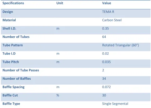
Table 1: Geometric data of the heat exchanger
Specifications Unit Value
Design TEMA R
Material Carbon Steel
Shell I.D. m 0.35
Number of Tubes 64
Tube Pattern Rotated Triangular (60°)
Tube I.D m 0.02
Tube Pitch m 0.035
Number of Tube Passes 2
Number of Baffles 34
Baffle Spacing m 0.072
Baffle Cut % 30
Baffle Type Single Segmental
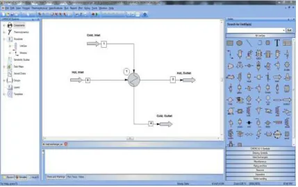
On the CHEMCAD user interface, a flow sheet was generated using the HTXR heat exchanger. Component used is only water on both the tube and shell side. The heat exchanger can be specified via different parameters in the setting windows. Thus, a simulation is run for this simple heat exchanger data. For the rigorous simulation, CC-THERM is called up at "Sizing: Heat Exchangers".
Available Online at www.ijpret.com 14
Figure 1: User Interface of CHEMCAD
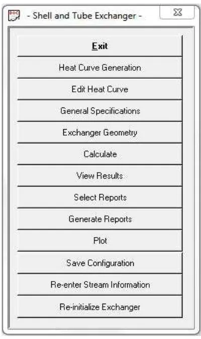
Available Online at www.ijpret.com 15 Other remaining data for the heat exchanger is stated in last “Miscellaneous Specifications” window. Once all settings have been completed, the main menu of the tubular heat exchanger is displayed in CC-THERM. The rigorous simulation of the heat exchanger with the previously entered data is performed with the command “Calculate”. The results of the calculation can be viewed in “View Results”. It is also possible to have the results exported to Excel or as a text file. The desired report section can be selected in “Select Reports” and afterwards generated with “Generate Reports”.
Figure 2: Shell and Tube Heat Exchanger Menu
Available Online at www.ijpret.com 16 transfer information and information describing the thermodynamic options and engineering units being used. It also contains an overall report of the tube side and shell side data (Chemstations, Inc., 2006). Difference in the values of pressure drop (ΔP), average velocity (V) and film coefficient (U) for these changes were studied and graphs were plotted for shell side or tube side(in case of number of tube passes). The average velocity (V) of the shell side fluid is the average of cross flow, end-zone and window-flow velocity. The pressure drop is the calculated pressure drop which include pressure drop due to friction in nozzles, sudden cross sectional area change and friction in shell or tube. It is the total of all these units. The shell side film coefficient is the shell side heat transfer coefficient based on tube outside surface area. The tube side film coefficient is the tube side heat transfer coefficient based on the tube inside area. Effect of number of tube passes was studied by assigning the values 2, 3 and 4. Effect of outer diameter of tubes was studied by assigning the values 0.023m, 0.024m, 0.025m, 0.026m and 0.027m. Effect of inner diameter of shell was studied by assigning the values 0.33m, 0.34m, 0.35m and 0.36m.
3. Results and Discussions
3.1 Effect of Tube Passes
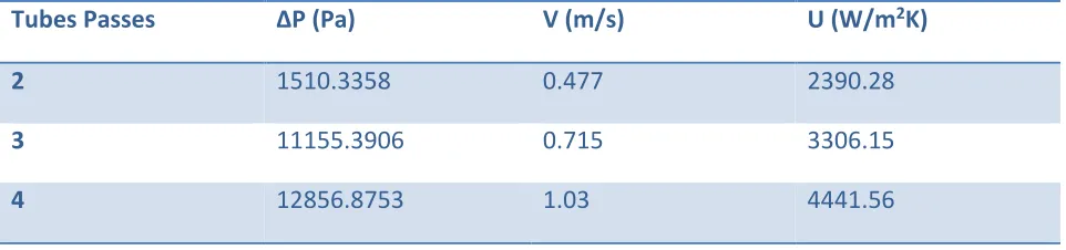
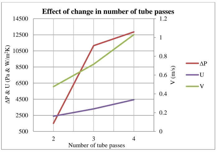
Table 2: Effect of tube passes
Tubes Passes ΔP (Pa) V (m/s) U (W/m2K)
2 1510.3358 0.477 2390.28
3 11155.3906 0.715 3306.15
Available Online at www.ijpret.com 17
Figure 3: Graph showing effect of change in number of tube passes
Figure 3 depicts the pressure drop, average velocity and film coefficient of the tube side against tube passes at constant outer diameter of tubes of 0.026m and inner diameter of shell of 0.35m. It was observed that as the tube side passes increases, the tube side average velocity, pressure drop and film coefficient increases rapidly.
The increase in number of tube side passes results in less area available for flow of the tube side fluid, thus the velocity of fluid increases. This results to the increase in pressure drop. As the velocity of fluid increases, the turbulence increases which results in more film coefficient of the tube side.
3.2 Effect of Outer Diameter of Tubes
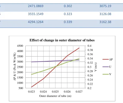
Table 3: Effect of outer diameter of tubes
Outer Diameter of Tubes (m)
ΔP (Pa) V (m/s) U (W/m2K)
0.023 609.4424 0.265 2979.92
0.024 1385.9312 0.282 3023.12
0 0.2 0.4 0.6 0.8 1 1.2 500 2500 4500 6500 8500 10500 12500 14500
2 3 4
V (m /s ) Δ P & U (P a & W /m 2K)
Number of tube passes
Effect of change in number of tube passes
ΔP
U
Available Online at www.ijpret.com 18
0.025 2471.0869 0.302 3075.19
0.026 3555.1549 0.323 3126.08
0.027 4294.1264 0.339 3162.38
Figure 4: Graph showing effect of change in outer diameter of tubes
Figure 4 depicts the pressure drop, average velocity and film coefficient of the shell side against outer diameter of tubes at constant value of 2 of the tube side passes and inner diameter of shell of 0.35m. It was observed that as the outer diameter of tubes increases, the shell side average velocity, pressure drop and film coefficient increases rapidly.
The increase in outer diameter of tube results in less flow area in the shell side, thus increasing the cross-flow velocity of the shell side fluid. This amounts to the increase in pressure drop. As the velocity of fluid increases, the turbulence increases which results in more film coefficient of the shell side.
0.2 0.22 0.24 0.26 0.28 0.3 0.32 0.34 0.36 0.38 0.4 500 1000 1500 2000 2500 3000 3500 4000 4500
0.023 0.024 0.025 0.026 0.027
V (m /s ) Δ P & U (P a & W /m 2K)
Outer diameter of tube (m)
Effect of change in outer diameter of tubes
ΔP
U
Available Online at www.ijpret.com 19
3.3 Effect of Inner Diameter of Shell
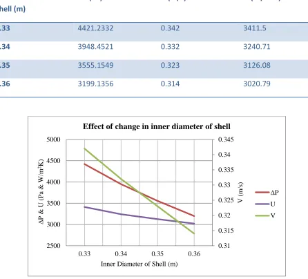
Table 4: Effect of inner diameter of shell
Inner Diameter of Shell (m)
ΔP (Pa) V (m/s) U (W/m2K)
0.33 4421.2332 0.342 3411.5
0.34 3948.4521 0.332 3240.71
0.35 3555.1549 0.323 3126.08
0.36 3199.1356 0.314 3020.79
Figure 5: Graph showing effect of change in inner diameter of shell
Figure 5 depicts the pressure drop, average velocity and film coefficient of the shell side against inner diameter of shell at constant value of 2 of tube side passes and outer diameter of tubes of 0.026m. It was observed that as the inner diameter of shell increases, the shell side average velocity, pressure drop and film coefficient decreases rapidly.
0.31 0.315 0.32 0.325 0.33 0.335 0.34 0.345
2500 3000 3500 4000 4500 5000
0.33 0.34 0.35 0.36
V
(m
/s
)
Δ
P
&
U
(P
a
&
W
/m
2K)
Inner Diameter of Shell (m)
Effect of change in inner diameter of shell
ΔP U
Available Online at www.ijpret.com 20 The increase in inner diameter of the shell increases the flow area on the shell side thus reducing the cross-flow velocity of the shell side fluid. This results in the reduction in pressure drop. As the velocity of fluid decreases, the turbulence decreases which decreases the film coefficient of the shell side.
4. Conclusion
Simulation for a shell and tube heat exchanger was carried out and evaluated using the CHEMCAD software. Reports for each simulation of changes in the specifications were generated and compared. It was observed that the shell side average velocity, pressure drop and film coefficient increases with increase in the outer diameter of tube and decreases with increase in inner diameter of shell. On the tube side, the average velocity, pressure drop and film coefficient increases with increase in the number of tube passes.
REFERENCES
1. Bilalis, Nicos, Computer Aided Design, Report produced for the EC funded project, Technical University of Crete, 2000.
2. Chemstations, Inc., CHEMCAD Version 6 User Guide, 2007. 3. Chemstations, Inc., CC-THERM Version 5.6 User’s Guide, 2006
4. Weise, Lisa, Heat exchanger simulation, Chemstations Europe GmbH, Germany.
5. Ali Kara, Y., Guraras, O., A computer program for designing of shell-and-tube heat exchangers, Applied Thermal Engineering 24, 2004, 1797-1805
6. Edwards, John E., Design and Rating of Shell and Tube Heat Exchangers, UK, 2008.
7. Dawande, S.D., Principles of Heat Transfer and Mass Transfer, Second edition, Denett & Co., 2009