Available Online At www.ijpret.com
INTERNATIONAL JOURNAL OF PURE AND
APPLIED RESEARCH IN ENGINEERING AND
TECHNOLOGY
A PATH FOR HORIZING YOUR INNOVATIVE WORKSUSPENDED MULTIBAND MICROSTRIP PATCH ANTENNA
SHIVLEELAWADLE, PROF. KHOBARAGADESANJAY, MADHURIMA MOHITE, BHUSHAN NAMALE
Dr. Babasaheb Ambedkar Technological University, Lonere
Accepted Date:
27/02/2013
Publish Date:
01/04/2013
Keywords
Coaxial feed,
HFSS (High Frequency
Structure Simulator)
version 11.0v software,
Suspended Micro strip
Antenna
Corresponding Author
Mr. ShivleelaWadle
Abstract
In this paper, we present the simulated results of triple band,
and suspended micro strip antenna with a single coaxial feed
has been proposed. The bandwidth of 80MHz, 200MHz, and
100MHz has been obtained corresponding to VSWR < 2, Return
loss (S11) less than -10dB, and 6.03dB Gain has been achieved
for the suspended antenna which is designed at 0.85GHz for
cellular application, 2.05GHz frequency for wireless
application, and 2.55GHz frequency for wi-max application.
Theoretical results have been validated with HFSS (High
Frequency Structure Simulator) 11.0v software. The design was
optimized to meet the best possible result. Substrate used was
FR4 which has a dielectric constant of 4.4 with height of
Available Online At www.ijpret.com
INTRODUCTION
The telecommunication does not stop to
increase; it always tries to reach the best
performances, thereliability and the
efficiency with the lowest possible costs. In
this domain, antennas establish a
basicelement allowing the transmission of
the electromagnetic waves in free space.
We find several types ofantennas which
different by cuts, geometrical shape,
capacity of transmission.However, the new
generation of the communication, mobile
or satellite communication provokes
considerable changes in patch antenna,
from which the various modern applications
require a functioning in wideband and
multiband band. Simulations of multiband
and Broadband microstrip Patch antenna
compacts conception with a wideband, a
triple frequency, an enhanced gain of
operation, was announced during the last
years.
In this paper, we are interested in the
simulation of suspended microstrip antenna
wideband, by the software Ansoft HFSS
"Hight Frequency Structure and simulator"
software. Microstrip patch antennas are
well known for their advantages in terms of
small weight, low profile and ease of
manufacture. However, the main limiting
factor in implementing these antennas in
many applications is their low impedance
bandwidth. One popularly used technique
of enhancing the bandwidth is to use
suspended microstrip, which in view of the
air layer next to the ground plane, offers
improved efficiency. The aim of this paper is
to study the bandwidth and radiation
characteristics of suspended microstrip
rectangular patch antennas with dielectric.
Using this technique a single layer
suspended microstrip antenna which offers
80MHz, 200MHz and 100MHZ (S11 < ¡10
dB) impedance bandwidth has been
reported in this paper.
The antenna developed here is suitable
for various wireless applications 0.85GHz,
for cellular phone, 2.05GHz is for wireless
application and 2.55 GHz is used in Wi-Max.
ANTENNA STRUCTURE AND DESIGN
The dielectric constant of the substrate
is closely related to the size and the
bandwidth of the micro strip antenna. Low
dielectric constant of the substrate
Available Online At www.ijpret.com dielectric constant of the substrate results
in smaller size of antenna. A trade-off
relationship exists between antenna size
and bandwidth.
The multiband suspended microstrip
patch antenna is designed on FR-4 substrate
at 50Ω matching impedance dielectric
constant εr = 4.4 and height from the
ground plane d=1.6mm, and height of air
gap is 6mm.The parameter of rectangular
microstrip patch antenna are
La=135mm,Wa=90mm,Lb=16mm,Wb=5.6m
m,Lc=30mm, and Ld= 17mm. the centre
square is rotated. In this patch two
hexagonal shapes are used to obtain dual
frequency and by varying the feeding point
we get the triple band. As the proposed
antenna is made suspended due to that
technique Gain is increases. Slots are cut in
the patch to increase the bandwidth.
The designed Microstrip antenna
resonates at 0.85GHz, 2.07GHz and 2.55GHz
frequency.
Fig.1. GEOMETRY OF PROPOSED ANTENNA
Fig.2. SUSPENDED MICROSTRIP ANTENNA
Fig3. FABRICATED ANTENNA
RESULTS AND DISCUSSION
Two measures of stating the impedance
matching are commonly used, both of
which are based on the reflection
coefficient, which is a measure of how
Available Online At www.ijpret.com source from the antenna’s terminals. The
first measure shows the reflection
coefficient on a logarithmic scale as |S11|.
Common definitions require that |S11| be
below the -10 dB line to declare an
acceptable impedance match. Figure (4)
shows the return loss curve. Results
showing that the antenna is resonating at
two frequencies. At 0.85GHz, 2.07 GHz and
2.55GHz the return loss values of
-19.64,-31.48dB, and -24.91dB are getting from the
current design.
Fig. 4. RETURN LOSS OF AN ANTENNA
A standing wave in a transmission
line is a wave in which the distribution of
current, voltage or field strength is formed
by the superimposition of two waves of
same frequency propagating in opposite
direction. Then the voltage along the line
produces a series of nodes and antinodes at
fixed positions. The second measure is
similar, but on a linear scale and is referred
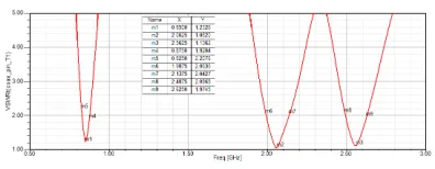
to as VSWR (Voltage Standing Wave Ratio).
In this terminology an antenna is deemed to
be well matched to the line where VSWR is
less than 2:1. Figure (5) showing the VSWR
Vs Frequency curve for the proposed
antenna. The VSWR of 1.23, 1.08, and 1.13
is obtained at two frequency values.
Fig. 5. VSWR OF AN ANTENNA
The bandwidth of an antenna refers
to “the range of frequencies within which
the performance of the antenna, with
respect to some characteristic, conforms to
a specified standard”. The most common
usage of bandwidth is in the sense of
impedance bandwidth, which refers to
those frequencies over which an antenna
may operate. Figure (6) shows the input
impedance smith chart and from which
bandwidth of 80MHz, 200MHz and 100MHz
Available Online At www.ijpret.com
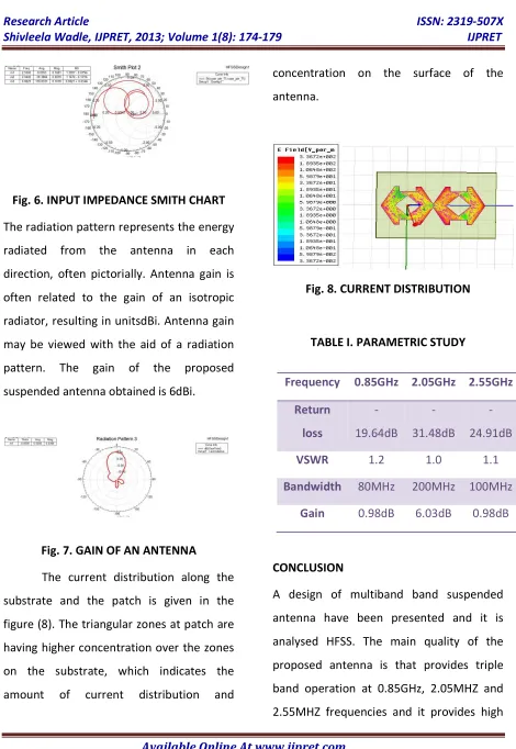
Fig. 6. INPUT IMPEDANCE SMITH CHART
The radiation pattern represents the energy
radiated from the antenna in each
direction, often pictorially. Antenna gain is
often related to the gain of an isotropic
radiator, resulting in unitsdBi. Antenna gain
may be viewed with the aid of a radiation
pattern. The gain of the proposed
suspended antenna obtained is 6dBi.
Fig. 7. GAIN OF AN ANTENNA
The current distribution along the
substrate and the patch is given in the
figure (8). The triangular zones at patch are
having higher concentration over the zones
on the substrate, which indicates the
amount of current distribution and
concentration on the surface of the
antenna.
Fig. 8. CURRENT DISTRIBUTION
TABLE I. PARAMETRIC STUDY
CONCLUSION
A design of multiband band suspended
antenna have been presented and it is
analysed HFSS. The main quality of the
proposed antenna is that provides triple
band operation at 0.85GHz, 2.05MHZ and
2.55MHZ frequencies and it provides high Frequency 0.85GHz 2.05GHz 2.55GHz
Return
loss
-19.64dB
-31.48dB
-24.91dB
VSWR 1.2 1.0 1.1
Bandwidth 80MHz 200MHz 100MHz
Available Online At www.ijpret.com gain of 6dBi. Moreover, this antenna has a
good effectiveness on the totality of the
two covered bands UMTS, WLAN and
wi-max frequency bands. The thickness of the
air gap is chosen such that theshifted
responses are brought in the desired range.
The proposed wide band antenna generates
resonant modes covering the
multi-operation bands for DCS/PCS/UMTS/WLAN
operations.
ACKNOWLEDGMENT
The authors express their thanks to the
Prof. S. V. Khobaragade, Prof. Amit Naik,
Mr. Vishwajit Sonawane and Department of
Electronics and Communication Engineering
of Dr. Babasaheb Ambedkar Technological
University, Lonere for their support.
REFERENCES
1. K. D. Prasad, “Antenna Wave and
Propagation”, SatyaPrakashan, New Delhi,
1995.
2. G. Kumar and K. P. Ray, “Broadband
Microstrip Antennas”, Artech House, 1992.
3. M. Dubey, D. Bhatnagar, V. K. Saxena and
J. S. Saini, “Broadband dual frequency
hexagonal microstrip antenna for modern
communication systems,” IEEE International
Conference on Emerging Trends in
Electronic and Photonic Devices & Systems,
2009,ELECTRO '09, pp. 303-306, Dec. 2009.
4. K. P. Ray, D. M. Suple and N. Kant,”
Suspended Hexagonal Microstrip Antennas
for Circular Polarization” VOL.5 NO.3 MAY
2010.