AN AUTOMATIC CALIBRATION METHOD BASED ON FEATURE
POINT MATCHING FOR THE COOPERATION OF WIDE-ANGLE
AND PAN-TILT-ZOOM CAMERAS
Hsien-Chou Liao, Ming-Ho Pan, Hung-Wei Hwang, Min-Chih Chang, Po-Cheng Chen
Chaoyang University of Technology, Department of Computer Science and Information Engineering 168 Jifong E. Rd., Wufong Township Taichung County, 41349, Taiwan (R.O.C.)
e-mail: [email protected], [email protected], [email protected], [email protected], [email protected]
Abstract. Wide-angle cameras are used to monitor large open areas, but moving objects on the image are often too small to view in detail. However, pan-tilt-zoom (PTZ) cameras have zooming capabilities that can be used to capture close-up images of a moving object. Therefore, the cooperation of these two types of cameras has been studied extensively in recent years. A calibration method is necessary to achieve the above cooperation. For any coordinate on the image plane of a wide-angle camera, this calibration method is needed to obtain the corresponding pan, tilt, and zoom values, known as the point correspondence of the PTZ camera. It is inconvenient to manually establish point correspondences, as shown in previous studies. Therefore, an automatic calibration method is proposed in this paper. The method is mainly based on the matching of feature points on the images of wide-angle and PTZ cameras. A feature point (FP) is extracted based on several edge operators derived from a 2D Gaussian smoothing function. A two-phase FP match is then designed to obtain the point correspondences. In the study of a prototype for capturing close-up images of moving objects, the calibration process took approximately 7 minutes for 44 FPs. The average successful rate of the capturing tasks was 82 percent. It shows that the automatic calibration method is feasible for the cooperation of wide-angle and PTZ cameras.
Keywords: dual-camera system, surveillance system, motion detection, moving object tracking, ubiquitous camera.
1. Introduction
The development of embedded systems and wire-less communication has caused IP-based cameras and IP-based surveillance systems to become popular. Unlike traditional digital cameras without computing capability, IP-based cameras usually have an embed-ded Linux system. They can operate individually and provide some basic services, such as motion detection or object tracking. IP-based cameras can be classified into three categories. One is the passive, i.e., wide-angle camera, which is used to monitor a fixed area with a fixed focal lens. Another is the active, i.e., pan-tilt-zoom (PTZ) camera, which is capable of in-creasing the monitoring area and enhancing the image quality. The last is designed for special purposes, such as Omni directional cameras or thermal cameras. The Internet connection increases the accessibility of IP-based cameras. The cooperation of multiple cameras has been studied recently for new services, such as consistent object labeling[1-2], pedestrian tracking, behavior analysis and so on. For the surveillance of large open areas, the objects in the image of a wide-angle camera may be too small to recognize. A PTZ
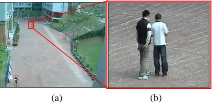
camera can be used to capture a close-up image of an object. However, its field of view (FOV) is limited when zooming in on a specific target. Therefore, the cooperation of wide-angle and PTZ cameras is complementary. This has been extensively studied recent years [3-7]. The cooperation scenario is shown in Figure 1. When an object appears in the image of a wide-angle camera, as shown in Figure 1(a), the PTZ camera can be controlled to capture a close-up image of the object, as shown in Figure 1(b).
(a) (b)
Figure 1.Cooperation scenario of wide-angle and PTZ cameras: (a) an object on the image of a wide-angle camera,
(b) the close-up image captured by a PTZ camera
It is very difficult for surveillance to manually cap-ture close-up images of all objects passing through an open area. An automatic system is needed. In order to achieve the cooperation of wide-angle and PTZ came-ras, camera calibration is the key process. For the coordinate of a specific object in the image of a wide-angle camera, the calibration calculates the corres-ponding pan, tilt, and zoom values needed to control the PTZ camera and capture the close-up image. In this paper, an automatic calibration method is pro-posed and a prototype system is also presented to achieve the above task. The calibration is based on the feature points (FPs) extracted by using a 2D Gaussian smoothing function [8]. Next, the corresponding pan and tilt values are obtained automatically using two phases: wide-angle FP matching and zoom-in FP matching. The zoom value is computed based on the height of the object. The established FP and pan/tilt correspondences are in the prototype.
The remainder of this paper is organized as fol-lows: Section 2 reviews related works; Section 3 presents the automatic calibration method; Section 4 presents the computation of pan, tilt, and zoom values; Section 5 describes the prototype and the experimental study; Section 6 presents the conclusion indicated by this study.
2. Related Works
The calibration method of cameras is important for the cooperation of multiple cameras. Methods de-scribed in previous studies can be classified into three categories:
(1) 3D world coordinate system: This category is based on a common 3D world coordinate system for multiple cameras to compute the desired pan and tilt angles of PTZ cameras [9]. R. Bodor et al. proposed a dual camera system for activity re-cognition [10]. The calibration is based on the inverse kinematics for computing pan and tilt angles from the 3D world coordinate. Marchesotti et al. also proposed a dual-camera system for face detection[11-12]. The calibration method is based on the Tsai’s method [13]. At least 12 pairs of 2D image plane and 3D world coordinates are needed to achieve precise calibration. Menudet et al. proposed a similar self-calibration method based on the image plane [14].
(2) Scene-dependent: This category is depended on specific features in the scene. Song and Tai pro-posed a calibration method for traffic monitoring [15], mainly based on parallel lane markings and lane width to compute the camera parameters. Lv et al. proposed a self-calibration method using vertical line segments of the same height [16]. Chen and Wang proposed a novel and efficient method for the calibration of multiple PTZ cameras [3] mounted on the ceiling of an indoor environment. The calibration is based on the tilt angle and altitude of the PTZ cameras. The image
processing technique is also used to infer the relative positioning and orientation among mul-tiple PTZ cameras. However, the calibration me-thod cannot be adapted to different PTZ camera installations or configurations.
(3) Ad hoc technique: This category utilizes special techniques for camera calibration. Xing et al. proposed a calibration method based on a genetic algorithm [17]. Tresadern and Reid proposed a calibration based on human motion [18]. Davis and Chen proposed a more complete calibration method for pan-tilt cameras, using an improved camera model to provide a large virtual calibration target by tracking the motion of an LED point feature [19]. However, it is troublesome to obtain the calibration data for different models of cameras. Lee et al. also proposed a manual calibra-tion method [20]. An image registracalibra-tion technique is used to establish panning, tilting, and zooming tables separately. However, the construction of the pan/tilt/zoom tables is still in convenient for different models of cameras. In a previous study by this researcher, a manual calibration method was proposed [21]. However, the problem still exists.
A number of disadvantages are mentioned in the previous studies. Therefore, an automatic calibration method is proposed simply based on the 2D image plane without considering the 3D world coordinate system. It is also scene-independent and general for the cooperation of wide-angle and PTZ cameras.
3. Automatic calibration method
When a wide-angle camera and a PTZ camera are calibrated, the corresponding pan, tilt, and zoom values can be obtained for any given coordinate on the image plane of a wide-angle camera. Therefore, when a moving object appears on the image plane of a wide-angle camera, the obtained pan/tilt/zoom values can be used to control the PTZ camera to focus on the object. An automatic calibration method is designed to estab-lish a set of point correspondences for obtaining the desired pan, tilt, and zoom values. The computation of the desired pan and tilt values is differed from that of the zoom value since the zoom value is related to the size of the object.
Zoom Cameras
Next, a normalized cross correlation (NCC) method is used to match the FPs on two images. A false match is also eliminated to establish the set of FP pairs. After this phase, a set of reference FPs in the image of the wide-angle camera and the corresponding FPs in the image of the PTZ camera in the maximum wide-angle mode is established.
Zoom -in FP matching Wide -angle FP matching
Match feature points Extract feature
points (FPs)
Eliminate false match
Extract feature points (FPs)
Zoom in every FP
Capture zoom-in image Wide-angle
camera
Capture real-time image
Capture wide-angle image
Extract and Match FP
Verify the matched FP FP pairs
FP and pan/tilt correspondences
PTZ camera
Centralize the FP and get pan/tilt values
Figure 2. The process of the proposed automatic calibration method for pan/tilt values
The second phase is zoom-in FP matching. The purpose is to obtain the corresponding pan and tilt value of the FP in every FP pair. Assume two FPs of one FP pair are denoted as PWi and PPi to represent
the FP on the image of wide-angle camera and the PTZ camera, respectively. Firstly, the PTZ camera is controlled to centralize and zoom in on PPi. However,
minor errors may exist while zooming, since a position on the wide-angle image is mapped into a rectangular area on the zoom-in image. In order to get precise pan and tilt values, a set of new FPs in the zoom-in image are extracted and matched with PWi.
Assume the new matched FP is denoted as PP’i. It
should be within a pre-defined central area; otherwise, it is discarded. If PP’i satisfies such criteria, the PTZ
camera is controlled to centralize on PP’i and get the
corresponding pan and tilt values from the PTZ camera. They are the desired correspondences of PWi.
After the above process, a set of point correspon-dences (FPs) in the image of the wide-angle camera and their corresponding pan and tilt values are established automatically.
The key steps of the above process, including the feature point extraction, matching, false matching elimination, and zoom-in FP matching are presented illustratively as follows.
(1) Feature point extraction
An FP is a point of human interest in an image, such as an intersection of two lines, a corner, and so on. In this paper, the set of FPs is extracted based on the method presented in 0. Several edge operators are used to extract FPs. For a specific position (x, y) on an image, the first partial derivatives of the 2D Gaussian smoothing function in x and y directions are denoted as Gσx and Gσy, respectively. They are computed by using Eq. (1):
( )
( )
2 2
2 2
2 2
2 2
, exp
2
, exp
2 x
y
x x y
G x y
y x y
G x y
σ
σ
σ σ
σ σ
⎛ + ⎞
= − ⎜⎜− ⎟⎟
⎝ ⎠
⎛ + ⎞
= − ⎜⎜− ⎟⎟
⎝ ⎠
, (1)
where σ is the standard deviation of the associated probability distribution. It is set to 2 for noise suppression. The gradients of an image I
( )
x,y smoothing byGx( )
x,yσ and G
( )
x y y ,σ in the x and y
directions can be computed by using Eq. (2):
( )
(
)
( )
(
)
, ,
, ,
x x
y y
I x y I G x y I x y I G x y
σ σ
σ σ
= ∗
= ∗ . (2)
The operator ∗ is a convolution operation. The modulus of the gradient vector of I
( )
x,y can be computed by using Eq. (3):( )
( )
2( )
2, x , y ,
Iσ x y Iσ x y Iσ x y
∇ = + . (3)
The position (x, y) is a feature point when it satisfies two conditions. The first condition is that the value ∇Iσ
( )
x,y is larger than a pre-defined threshold of 20. The second condition is that ∇Iσ( )
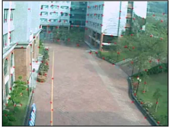
x,y is the local maxima within a pre-defined area of 27×27.According to the above method, an example of extracted FPs is shown in Figure 3 and marked with a red cross.
(2) Feature point matching
Two sets of FPs are extracted separately from the image of the wide-angle camera and the wide-angle image of the PTZ camera. Next, a normalized cross correlation (NCC) method is used for FP matching0. NCC is commonly used as a metric to evaluate the similarity of FPs in two sets. An example of FP matching is shown in Figure 4. The matched FP has the same number as shown in Figures 4(a) and 4(b).
(a) (b)
Figure 4. An example of feature point matching: (a) the image of the wide-angle camera,
(b) the image of the PTZ camera
(3) False match elimination
The set of FP pairs matched using NCC may con-tain false matches (such as FPs No. 21 and 26 in Figure 4). These false matches cannot be point cor-respondences and must be eliminated. The elimination is based on their geometric relationship. The above example after false match elimination is shown in Figure 5.
(a) (b)
Figure 5. An example of false match elimination: (a) the image of the wide-angle camera,
(b) the image of the PTZ camera
(4) Zoom-in FP matching
In this step, the corresponding pan and tilt values of every FP pair are obtained using the above FP matching technique with the zoom-in image of the PTZ camera. For matched FP pair PWi and PPi, the
PTZ is controlled to zoom in on the PPi to capture a
close-up image of the area around it. New FPs in the zoom-in image are extracted. Then, PWi is matched
with the new FPs to find the new matched FP, PP’i.
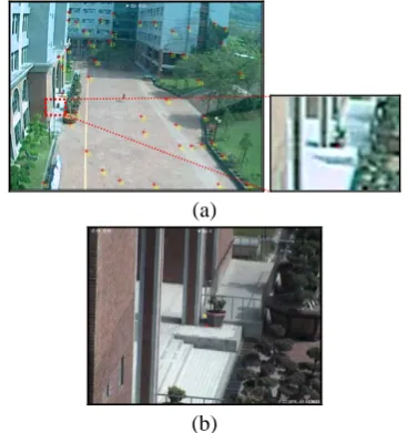
An example of zoom-in FP matching is shown in Figure 6. In Figure 6(a), the original size of the image containing PWi is shown on the right-hand side. The
zoom-in image of PPi is shown in Figure 6(b). The red
dot is the matched PP’i. It is the ideal condition where
PP’i is in the precise center of the zoom-in image.
The new matched FP, PP’i, is verified to ensure
there is no possible false match. In general, if the PTZ camera is controlled to centralize and zoom in on PPi,
the matched PP’i should be within the central area.
Otherwise, PP’i is a false match. An example is shown
in Figure 7 to illustrate the verification of PP’i. In
Figure 7(a), the yellow cross is the center of the image. Assume the matched PP’i is marked with a red
cross and is within the red-dashed pre-defined circle. The PTZ camera is controlled to centralize PP’I again
and overlap it with the center of the image as shown in Figure 7(b). If PP’i is not within the pre-defined circle
as shown in Figure 7(c), it is a false matching and discarded.
(a)
(b)
Figure 6. An example of zoom-in FP matching:(a) the image containing the FP in its original size,(b)the corresponding zoom-in image of the PTZ camera
When the PP’i is centralized as shown in Figure
7(b), the pan and tilt values of the PTZ camera are recorded with PWi as a point correspondence. These
point correspondences are the final result of the auto-matic calibration method. They are used to compute the desired pan and tilt values for any given coordi-nate on the image plane of the wide-angle camera.
(a) (b)
(c)
Figure 7. The demonstration of FP verification: (a) the matched FP (red) and the center of the image (yellow),
Zoom Cameras
4. The computation of pan/tilt/zoom values
For an object in the image of the wide-angle ca-mera, assume its position (x’, y’) and size (w’, h’) can be known. Its position is used to compute the corres-ponding pan and tilt values for the PTZ camera, based on the set of point correspondences established using the automatic calibration process. The object size is used to compute the suitable zoom values. In order to compute the desired pan and tilt values,(x’, y’) is assumed to the next possible position of a moving object. It is marked with a blue-dashed rectangle, as shown in Figure 8. Next, the closest FPs of point cor-respondences to (x’, y’)in the vertical and horizontal line are found separately and denoted as (x1, y1) and
(x2, y2). Assume the corresponding pan and tilt values
for (x1, y1) and (x2, y2) are (p1, t1) and (p2, t2),
respectively. The desired pan and tilt values, (p’, t’), for (x’, y’) are computed based on a trigonometric formula, as shown in Eq. (4):
( )
( )
1 2
1 1
1 2
1 2
1 1
1 2
' '
' '
p p
p x x p
x x
t t
t y y t
y y
⎛ − ⎞
= − ×⎜ ⎟+
−
⎝ ⎠
⎛ − ⎞
= − − ×⎜ − ⎟+
⎝ ⎠
. (4)
Figure 8. The computation of pan/tilt values
(a) (b)
Figure 9. An example of measuring zoom-in image size: (a) wide-angle image (zoom=1),
(b) the zoom-in image (zoom=5,000)
In advance, the computation of the zoom value is according to the size of the moving object. Before the computation, a look-up table is first established. For the physical zoom values (1 to 14,000 for an AXIS-215 PTZ camera), the zoom-in image sizes are re-corded every 500 increments. An example is used to illustrate the measurement of the zoom-in image size as shown in Figure 9. Figure 9(a) is the wide-angle image with the zoom value set to 1. Figure 9(b) shows the zoom value set to 5000. It is only a partial view of the wide-angle image, and is marked by a red rect-angle. Next, the height of the rectangle in Figure 9(a) is recorded in the look-up table. A partial look-up table
is listed in Table 1. Only the height is considered here, since the main target is a person in an open area. The height of a person is usually larger than its width.
According to such a look-up table, a suitable zoom value can be computed for a specific object height. Assume the height of a moving object is denoted as h’. The pre-defined ratio of the zoom-in image to an object is denoted as R. R×h’ is the expected height of the zoom-in image. It can be found between two heights in the look-up table, denoted as h1
andh2(h1≤h2). The corresponding zoom values are
denoted as z1 andz2. The desired zoom value z’ is
computed using the following equation.
(
)
2 11 1
2 1
' ' z z
z R h h z
h h
⎛ − ⎞
= × − ×⎜ ⎟+
−
⎝ ⎠ . (5)
Table 1. A partial look-up table of the zoom value
Zoom Height
14000 9
13500 10
13000 12
12500 14
12000 16
... ...
5. The prototype system
A prototype system was implemented using Visual C# 2008. It is designed for capturing close-up images of every object passing through an open area. The system consists of one wide-angle camera and mul-tiple PTZ cameras. The automatic calibration process is performed individually on every PTZ camera to establish the point correspondences. The screenshot of the automatic calibration tool is shown in Figure 10. The image of the wide-angle camera is shown on the left-hand side. The image of the PTZ camera is shown on the right-hand side. Numerous FPs are marked on the wide-angle image. The FP circled in red denotes it being in the zoom-in FP matching phase. The corres-ponding FP on the zoom-in image is shown on the right-hand side. There are 51 FPs in total, with14 FPs finished and one FP failing to pass the verification step shown at the bottom of the tool.
After the calibration process is finished, the prototype system can perform the automatic close-up image capturing task. The screenshot is shown in Figure 11. The real-time image of the wide-angle camera is shown in the upper-right part. The moving objects are detected based on the background subtraction technique, and are marked with different colors to represent their status. An object marked with a red, yellow, or blue rectangle denotes its close-up image as being uncaptured, capturing, and captured, respectively. The real-time image of the PTZ camera is displayed at the top of the images on the right-hand side. The images under the real-time image of the PTZ camera are continuous shots of a moving object. When the PTZ camera is rotating or the object is moving, the image may be blurred. Continuous shots enable at least two clear images to be found among all the shots. The actual size of the images is 640×480 pixels. The first four images of the five continuous shots are displayed on the user interface. The continuous shots of two objects are shown in Figure 12.
Figure 11. Screenshot of the prototype system
(a)
(b)
Figure 12. Two examples of continuous shots: (a) vertical movement, (b)horizontal movement
In advance, two experiments were designed to evaluate the performance of the prototype. The first experiment was to measure the elapsed time of the automatic calibration tool. The time is influenced by the number of FPs. In the experiment, there were 44 FPs and the elapsed time was approximately 7 minutes. However, only one click was required to acti-vate the calibration process, meaning the time required was very short. Conversely, manual calibration re-quires 14 minutes for the same number of FPs. The
above result shows that the automatic calibration process has improved efficiency.
In the second experiment, the system performed close-up image capturing tasks at two different time periods: normal and rush hour. A capturing task is classified into success or failure as defined below: • Success: If the head of a moving object appears
completely in one of the continuous shots, the task is classified as a success.
• Failure: If either the head of a moving object is not captured, or no moving object exists in any of the continuous shots, the task is classified as a failure. Additionally, the same checking step presented in the researchers’ previous study was used to examine whether a task was failure 0. If the checking result of the continuous shots fails, the system will repeat the capturing task until either the task is successful or the object leaves the FOV of the wide-angle camera. The experimental results are listed in Table 2. The number of objects at normal and rush hour for 20 minutes were 173 and 312, respectively. The success percent at normal and rush hour was 82.6 and 80.4 percent, respectively. The average number of captures per ob-ject was computed based on the repeat count, and was 1.53 and 1.42 at normal and rush hours, respectively.
Compared with the researchers’ earlier prototype using manual calibration methods during the normal hour period0, the success rate of 82.6 percent was lower than that of the previous study (87.8 percent). However, at 1.53 times, the average number of captures per object was better than that of the previous study (2.59 times). This shows that the point correspondences established using the automatic calibration method are precise and useful for close-up image capturing tasks.
Table 2. The results of moving object capturing tasks Periods Categories Normal Hour Rush Hour Number of objects 173 312
Success 143 (82.6%) 259 (80.4%)
Repeat 92 132
Average number of captures per object
1.53 (265/173)
1.42 (444/312)
6. Conclusions
Zoom Cameras
established, the desired pan and tilt values can be computed for any given coordinate on the image of the wide-angle camera. According to the experiment, the success rate of close-up image captures was 82.6 percent. If the success rate is expected to improve fur-ther, the predictions of the moving object positions and the elapsed time of camera rotation are two main factors that need to be considered. The prototype can also be refined to provide different tasks for different situations. For example, close-up image capturing tasks are suitable for a large numbers of moving ob-jects in an open area. However, tracking tasks are suitable for small numbers of moving objects during specific periods of time. The prototype can be context-aware and switch its task automatically.
Acknowledgement
This work was funded by the National Science Council under grant NSC97-2815-C-324-009-E.
References
[1] S. Khan, M. Shah. Consistent labeling of tracked objects in multiple cameras with overlapping fields of view, IEEE Transactions on Pattern Analysis and Machine Intelligence, Vol.25, Oct. 2003, 1355-1360.
[2] S. Calderara, A. Prati, R. Vezzani, R. Cucchiara. Consistent labeling for multi-camera object tracking,
Lecture Notes in Computer Science, Vol.3617, 2005, pp. 1206-1214.
[3] I.H. Chenand, S.J. Wang. Efficient vision-based ca-libration for visual surveillance systems with multiple PTZ cameras. Proceedings of IEEE International Conference on Computer Vision Systems (ICVS 2006), 4-7 Jan. 2006, 24-24.
[4] S. Khan, O. Javed, Z. Rasheed, M. Shah. Human tracking in multiple cameras. Proceedings of Eighth IEEE International Conference on Computer Vision
(ICCV 2001), 2001, Vol.1, 331-336.
[5] Z. Tao, M. Aggarwal, R. Kumar, H. Sawhney. Real-time wide area multi-camera stereo tracking.
Proceedings of IEEE Computer Society Conference on Computer Vision and Pattern Recognition, 20-25
June, 2005, Vol.1, 976-983.
[6] C. Micheloni, G.L. Foresti, L. Snidaro. A network of co-operative cameras for visual surveillance.IEE Proceedings of Vision, Image and Signal Processing, 8 April, 2005, Vol.152, 205-212.
[7] R. Yi, D. Xu, G. Junbin, M. Antolovich. Novel me-thods for high-resolution facial image capture using calibrated PTZ and static cameras. Proceedings of IEEE International Conference on Multimedia and Expo, 23 June, 2008, 45-48.
[8] J.W. Hsieh. Fast stitching algorithm for moving object detection and mosaic construction. Image and Vision Computing, Vol.22, 2004, 291-306.
[9] T.S. Shen, C.H. Menq. Automatic camera calibration for a multiple-sensor integrated coordinate measure-ment system. IEEE Transactions on Robotics and Automation, Vol.17, No.4, 2001, 502-507.
[10] R. Bodor, R. Morlok, N. Papanikolopoulos. Dual-camera system for multi-level activity recognition.
Proceedings of 2004 IEEE/RSJ International Con-ference on Intelligent Robots and Systems (IROS
2004), Vol.1, Sendai, Japan, 28 September-2 October
2004, 643-648.
[11] L. Marchesotti, L. Marcenaro, C. Regazzoni. A multi-resolution outdoor dual camera system for ro-bust video-event metadata extraction. Proceedings of
2002 International Conference on Information Fusion,
Vol.2, Italy, 8-11 July 2002, 1184-1189.
[12] L. Marchesotti, L. Marcenaro, C. Regazzoni. Dual camera system for face detection in unconstrained environments. Proceedings of 2003 International Con-ference on Image Processing (ICIP 2005), Vol.1, Italy, 14-17 September 2005, I-681-684.
[13] R.Y. Tsai. A versatile camera calibration technique for high-accuracy 3D machine vision metrology using off-the-shelf TV cameras and lenses. IEEE Journal of Roboticsand Automation, RA-3(4), Aug. 1987, 323-344.
[14] J.F. Menudet, J.M. Becker, T. Fournel, C. Mennes-sier. Plane-based camera self-calibration by metric rectification of images. Image and Vision Computing,
Vol.26, No.7, 2 July 2008, 913-934.
[15] K.T. Song, J.C. Tai. Dynamic calibration of pan–tilt– zoom cameras for traffic monitoring. IEEE Transactions on Systems, Man, and Cybernetics-Part B: Cybernetics, Vol.36, No.5, 2006, 1091-1103. [16] F. Lv, T. Zhao, R. Nevatia. Camera calibration from
video of a walking human. IEEE Transactions on Pattern Analysis and Machine Intelligence, Vol.28,
No.9, Sept. 2006, 1513-1518.
[17] Y. Xing, Q. Liu, J. Sun, L. Hu. Camera calibration based on improved genetic algorithm. Proceedings of IEEE International Conference on automation and logistics, 18-21 Aug. 2007, 2596-2601.
[18] P.A. Tresadern, I.D. Reid. Camera calibration from human motion. Image and Vision Computing, Vol.26,
No.6, June 2008, 851-862.
[19] J. Davis, X. Chen. Calibrating pan-tilt cameras in wide-area surveillance networks.Proceedings of the Ninth IEEE International Conference on Computer Vision (ICCV), Vol.1, Nice, France, 14-17 October
2003, 144-149.
[20] C.H. Lee, M.G. Wen, C.C. Han, D.C. Kou. An automatic monitoring approach for unsupervised parking lots in the outdoors. Proceedings of the 39th Annual 2005 International Carnahan Conference on Security Technology (CCST'05), 11-14 Oct. 2005, 271-274.
[21] H.C. Liao, Y.C. Cho. A new calibration method and its application for the cooperation of wide-angle and pan-tilt-zoom cameras. Information Technology Jour-nal, Vol.7, No.8, 2008, 1096-1105.