The Experience of Implementing Model-Driven Engineering Tools
in the Process Control Domain
Giovanni Godena
1,4, Tomaž Lukman
2, Marjan Heričko
3, Stanko Strmčnik
11 Jožef Stefan Institute, Department of Systems and Control, Jamova 39, 1000 Ljubljana, Slovenia, e-mail: [email protected], [email protected]
2 Iteratec GmbH, Inselkammerstraße 4, 82008 München - Unterhaching, Germany, e-mail: [email protected]
3 University of Maribor, Faculty of Electrical Engineering and Computer Science, Smetanova ulica 17, 2000 Maribor, Slovenia,
e-mail: [email protected]
4 Jožef Stefan International Postgraduate School, Jamova 39, 1000 Ljubljana, Slovenia
http://dx.doi.org/10.5755/j01.itc.44.2.6258
Abstract. Model-driven engineering (MDE) is a software-engineering paradigm that is being introduced into a growing number of domains. One of the most important success factors for a new MDE approach is the availability of the appropriate tool support for it. Although the literature discusses the development of support tools, only a few reports and analyses are available about the development of tool support for real-life modeling languages and MDE approaches. The goal of this paper is to fill this gap through an experience report about developing a tool-suite prototype for an MDE approach for the process control domain that is capable of supporting the development of real-life process control software. Before the work presented in this paper an initial prototype tool suite was already developed. However, it was not able to adequately support industry-scale projects. The paper starts with an analysis of the past development of this already-existing laboratory prototype and then moves on to a report about the development of the industrial prototype, which is influenced by the findings of the analysis. Then a comparison between the two prototypes is made and the lessons learned are described, which may be useful to practitioners who attempt to develop support tools for an MDE approach that are useful in practice. The most important lesson learned is that when developing tool support for complex modeling languages, the traditional development approach should not be easily rejected.
Keywords: model-driven engineering, process control software, domain-specific modeling languages, ProcGraph.
1. Introduction
In the struggle to improve the engineering of software, many concepts and technologies have been proposed. One of them is model-driven engineering (MDE), which advocates the systematic and disciplined use of precise models of a system under design throughout the software lifecycle [1]. Its primary development entities are models that can be (semi-) automatically transformed into refined models and eventually into executable code [2]. MDE is a software-engineering paradigm that has the potential to sustainably raise the productivity, increase the software quality [3] and reduce the complexity of software and systems development [1]. Despite these promises there are still only a few empirical studies relating to MDE and its use in practice [4]. An overview of the empirical
where one of the largest problems was the development of the tool suite, consisting of a model repository, a model editor and a code generator. In the work preceding the research presented in this paper, we already developed an initial tool-suite prototype. This enabled the development of smaller applications, which are rarely found in practice but tend to be conceived as examples that can be used for a proof-of-concept in the laboratory. The development of this laboratory prototype, which is reported in [8], proved to be demanding and complex. As a result, this crucially influenced the next step, i.e., the development of an industrial prototype tool suite for MAGICS that enables the development of real-life applications that have the scale and complexity commonly found in practice.
The aim of this paper is to show how the experience gained during the development of the laboratory prototype influenced the development of an industrial prototype of the MAGICS tool suite. An important part of the paper is the comparison of the two prototypes and the presentation of the lessons learned.
The main motivation for sharing our experience is the fact that MDE practitioners are faced with the challenge of developing practically useful tool support for new MDE approaches and also that the literature recognizes that developing such tool support is difficult [7] and important [3, 5]. An additional motivation is the scarce literature on this topic. This experience report should be especially interesting for practitioners dealing with not-trivial, real-life modeling languages and the corresponding tool support. It should also be interesting for the experts (researchers and practitioners) from the process control domain that are evaluating the state of the art approaches for software engineering in this domain [9].
The next section presents the related work about MDE and the tool support for it. Section 3 introduces our previous work, i.e., the MAGICS approach and a laboratory prototype tool suite for it. Section 4 analyses the development of the laboratory prototype tool suite. Section 5 presents the development of the industrial prototype, which is influenced by the results of the analysis from the previous section. Section 6 contains the findings of our experience report, which are articulated in a comparison between the laboratory and the industrial prototype and the lessons learned. The last section presents our conclusions.
2. Related work
Typically, the MDE approach relies on three main components: modeling languages, model transfor-mations and support software tools.
The modeling languages for software and systems can be classified into general-purpose modelling languages (GPMLs), which support modeling in a variety of domains and domain-specific modelling languages (DSMLs), which are intended for modeling in one domain using the abstractions common to that domain [10]. Both of these can be used in the MDE
approach, as long as they are formal. However, it is apparent that a DSML will usually produce a more concise and direct specification and, therefore, more effective solutions for problems in its domain than a GPML [11]. This means the question that should be asked is what is the most effective method for defining a DSML [11]? DSMLs are usually defined through a Unified Modeling Language (UML)-based definition or a metamodeling-based definition [12, 13]. The former approach specializes the UML [14], which is a GPML in itself, for a specific domain through the definition of a UML profile. The latter approach defines the DSML “from scratch” with the use of a metamodeling language, e.g., the Meta-Object Facility (MOF) [15]. A similar question arises in the area of Domain-Specific Languages (DSLs) [16, 17], because they can be realized as an external DSL, which corresponds to a UML-based definition of a DSML, or as an internal DSL, which corresponds to a metamodeling-based definition of a DSML.
A model transformation generates one or more target models from one or more source models, based on a set of model-transformation rules. With model transformations, MDE can automate many of the complex but routine development tasks that are often performed manually [18], such as model refactoring or the generation of code from models.
To enable MDE in practice and fulfill its potential, sophisticated tools must be developed that support DSML(s) and the defined model transformations. A survey performed among industry participants showed that the availability of tool support is the most influential factor in the decision about whether to adopt a specific MDE approach [3]. Several alternatives exist for the development of tool support for the selected DSML. The development approach depends on the way the DSML was defined:
had to be covered by integrating MagicDraw with an Eclipse-based editor, which is inferior to an IDE solution.
Metamodeling-based DSML. In general, developing tool support for such DSMLs demands more effort and highly specialized expertise [12]. On the other hand, it offers more flexibility than UML-based DSMLs. Two different development options are available:
Traditional development. No specialized tools for MDE are used during the development of the tool support. The literature [2, 24] suggests that traditional development is demanding, resource intensive (it may require effort ran-ging from several person-months and up to a couple of person-years), and inflexible for maintenance. However, the main advantage of traditional development is that it is not limited by the capabilities of the used specialized tools. Therefore, even very specific tool-suite requirements can be realized.
Development with metamodeling tools. Metamodeling tools, for example, GME [25], GMF [24], and MetaEdit+ [2], can automa-tically generate (portions of) the needed tool suite based on a formal definition of the DSML and the model transformations. Consequently, metamodeling tools have the potential to speed up the development and reduce the required effort and development complexity [2]. The main disadvantage of this approach is the relative immaturity of this technology [8].
3. Previous work
In our previous work a new MDE approach for process control software, called MAGICS [8], was defined. It was developed because the state of the practice in this domain is failing to address the needs of the market [26] and is putting too much focus on the implementation phase, with little or no activity in the earlier software lifecycle phases [8]. Other proposed approaches, among which are also MDE approaches, have not been widely adopted by industry because of their immaturity and particularly because they do not address important issues of the process control domain [9]. The MAGICS approach consists of the two development levels that are shown in Figure 1. The first level (infrastructure engineering) is concerned with the definition of the development process and guidelines, the definition of a DSML, the specification of the model transformations, and the development of a tool suite. This tool suite makes it possible to model the process control software and to perform the automatic code generation for programmable logic controllers. This tool suite can be extended with additional tools, e.g., a model validator and a model refactoring tool. The ProcGraph language [27] was chosen to be the DSML used in MAGICS, because it was developed
in-house and it contains process-centric abstractions, a sophisticated behavioral model for these abstractions, and explicit modeling of the dependencies between them [8]. ProcGraph has been successfully used as a modeling (specification) language over the past 15 years in more than 20 industrial projects, ranging in size from a couple of hundred to a couple of thousand signals. In the second level (application engineering), the process control software is engineered using the results of the infrastructure level. The application-engineering level uses the infrastructure for the development of process control software. The infor-mation flow from the application-engineering level to the infrastructure-engineering level incorporates the knowledge that is being accumulated during the application-development process. This information can be potentially generalized and incorporated into new versions of the infrastructure, which would further improve the application engineering or extend the range (i.e., the variability) of the software that can be engineered.
The development of the laboratory prototype tool suite, which is also part of the previous work, is extensively described in [8] and will be summarized in the remainder of this paragraph, so that the rest of the paper can be understood. The laboratory prototype consists of a model repository, a model editor and two code generators. The ProcGraph DSML was defined with metamodeling; therefore, the support tools could be either developed with metamodeling tools or the traditional approach. We chose the metamodeling-tools approach, because of the already-mentioned benefits that are reported in the literature and because we wanted the formalized language to have as many of the original features as possible. A comprehensive expla-nation is beyond the scope of this paper and can be found in [8]. A systematic evaluation of the available metamodeling tools [28] has shown that the most suitable metamodeling tools for MAGICS were the combination of EMF (Eclipse Modeling Framework), GMF (Graphical Modeling Framework) and openArchitectureWare. The model repository was developed with the EMF, which is the central tool for creating structural model repositories for the Eclipse platform. GMF was selected for the development of the graphical model editor and can generate a visual model editor based on different models of this editor. OpenArchitectureWare was used for the implement-tation of the code generators, because it is a widely used model-to-text engine that seamlessly works with EMF metamodels.
4. An analysis of the laboratory-prototype
development
of the development of the laboratory prototype we focused on three different viewpoints, i.e., the requirements realization, the problems during the use of the laboratory prototype and the problems occurring during its development.
4.1. Requirements perspective
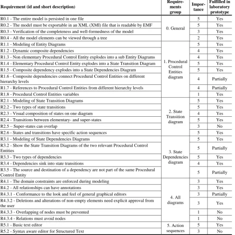
The analysis started with an overview of the requirements and an assessment of their fulfillment. A measurement scale from 1 to 5 was defined in order to denote the importance of each requirement, whereby 1 represents for the lowest importance and 5 the highest importance. The laboratory prototype did not implement 4 of 31 defined requirements and partially implemented 5 requirements. The results of the assessment are shown in Table 1.
4.1.1. The requirements not or partially implemented because of problems with GMF
Among the requirements that were partially ful-filled, we should highlight the requirements R1.6 and R1.7 (they enable the construction of composite depen-dencies between the Procedural Control Entities on different hierarchy levels) and the requirement R3.2 (it dynamically depicts the changes of the states and transitions on State Dependencies Diagrams). The essence of these requirements is to establish the syn-chronization between different ProcGraph diagram types that contain the same graphical information, which can be entered only in the first diagram type,
whereas in the second diagram type it represents static information that cannot be modified, only additional information can be superimposed. A change in the first diagram type should then be propagated to the second diagram type. As a concrete example let us mention a case of two entity state diagrams and a state dependen-cies diagram, containing the two mentioned state diagrams (which cannot be modified there) and super-imposed information on the state transition dependen-cies between the two entities. For more reference on the ProcGraph behavior model consider [8, 27]. Establi-shing synchronization is not supported by GMF itself, but it had to be realized by altering the GMF-generated code, by overriding numerous methods from classes of the GMF framework and by performing extensive testing and debugging. Despite the effort invested in the realization of these requirements we were not able to implement a fully working synchronization, so that synchronization errors occasionally occurred (mainly with large-scale models). Because of this and because of the lack of examples of GMF-based editors with working synchronization, we decided that a partial implementation would be sufficient for the laboratory prototype. We were not able to determine whether a proper synchronization is even achievable with GMF. The requirement R3.5 was only partially fulfilled, because of the synchronization problems. Similar observations in GMF have been made in [29] during the implementation of a DSML for elevator controllers. This problem is common in non-orthogonal modeling languages, i.e., those that represent the same
Figure 1. A scheme of the MAGICS approach [8]
A
p
p
li
c
a
ti
o
n
e
n
g
in
e
e
ri
n
g
In
fr
a
s
tr
u
c
tu
re
e
n
g
in
e
e
ri
n
g
Model transformations
definition
DSML development
Software tool suite engineering
Code generator #2 development Code generator #1 development Model editor development
Model repository development
Model repository
Process control software engineering
Model editor
Code gen. #1
Process control software Code gen. #2 Model
transformation rules
DSML definition
Application-specific knowledge
Application requirements
Process definition, guidelines etc.
Table 1. Overview of the requirements fulfillment for the laboratory prototype
Requirement (id and short description)
Require-ments group
Impor-tance
Fulfilled in laboratory prototype R0.1 - The entire model is persisted in one file
0. General
5 Yes
R0.2 - The model must be exportable in an XML (XMI) file that is readable by EMF 5 Yes R0.3 - Verification of the completeness and well-formedness of the model 3 Yes
R0.4 - All the model elements can be viewed through a tree 2 Yes
R1.1 - Modeling of Entity Diagrams
1. Procedural Control Entities diagram
5 Yes
R1.2 - Dynamic composite dependencies 4 Yes
R1.3 - Non elementary Procedural Control Entity explodes into a sub Entity Diagrams 4 Yes R1.4 - Elementary Procedural Control Entity explodes into a State Transition Diagram 5 Yes R1.5 - Composite dependency explodes into a State Dependencies Diagram 5 Yes R1.6 - Composite dependencies connect Procedural Control Entities on different
hierarchy levels 4 Partially
R1.7 - References to Procedural Control Entities from different hierarchy levels 4 Partially
R1.8 - Procedural Control Entities variables 1 Yes
R2.1 - Modeling of State Transition Diagrams
2. State Transition
diagram
5 Yes
R2.2 - Two types of state transitions 5 Yes
R2.3 - Visual composition of states on one diagram 4 Yes
R2.4 - Transitions between elementary- and super-states 5 Yes
R2.5 – Super-states can overlap 3 No
R2.6 - States and transitions have specific action sequences 5 Yes
R3.1 - Modeling of State Dependencies Diagrams
3. State Dependencies
diagram
5 Yes
R3.2 - Show the State Transition Diagrams of the two relevant Procedural Control
Entities 5 Partially
R3.3 - Two types of dependencies 5 Yes
R3.4 - Dependencies sink into state transitions 4 Yes
R3.5 - The source and destination of a dependency are not part of the same Procedural
Control Entity 5 Partially
R4.1 - The domain constraints are enforced during modeling
4. All diagrams
3 Yes
R4.2 - All relationships can have annotations 3 Yes
R4.3.1 - Conformance to the look and feel of general graphical editors 3 Partially R4.3.2 - Deletions and alterations of non-empty elements need explicit approval from
the user 3 Yes
R4.3.3 - Overlapping of nodes must be prevented 1 No
R4.3.4 - Relations must avoid nodes 1 No
R5.1 - Basic text editor 5. Action
sequences
5 Yes
R5.2 - Syntax aware editor for Structured Text 3 No
information in different diagrams. This is also the case in UML. This problem was also discussed by Grundy, et al. [30].
Another important unfulfilled requirement is R2.5, which addresses the overlapping super-states. Even after an extensive experimentation (with a great deal of coding) and an unsuccessful search for similar already-implemented solutions we were still unable to fulfill this requirement with GMF.
Here, it is very important to mention that in order to exclude problems that could be related to our incom-petence we have contacted one of the developers of GMF and also independent consulting companies to help us address the flaws in GMF. Unfortunately, this approach has also not led to a solution.
4.1.2. The requirements not or partially implemented for other reasons
R4.3.4 were also left out, because of their low business value and the lack of resources.
4.2. Usability perspective
The next step of the analysis was an assessment of the laboratory prototype support tools from the end users’ perspective. Despite the fact that non-functional requirements were not explicitly specified, it is clear that the users have a minimum set of expectations that should be met. These regard foremost the quality of the software, which according to Sommerville [31] can be considered as one of the subsets of non-functional requirements. The risk exists that if the tools do not fulfill the expectations of the users regarding the non-functional requirements, they will be considered as useless [31]. Testing has shown that the laboratory prototype has the following weaknesses from the end users’ perspective:
Lack of reliability, which was manifested through instability. During the use of the laboratory proto-type, on average two errors per hour occurred (the actual occurrence rate depends on the complexity of the model). Occasionally, errors occurred that caused the termination of the editor and the loss of unsaved work. We were not able to solve these problems, despite many attempts. Among the causes for these problems were the problems related to the synchronization between the diagrams. Relatively low efficiency, which is a consequence
of the slow editor. When editing large-scale models, a shortage of memory occasionally occurred (note that the editor was tested on average computers).
4.3. Development perspective
The last part of the analysis concerned the develop-ment process of the laboratory prototype, which turned out to be both demanding and difficult. Most of the experienced problems were a consequence of the GMF framework shortcomings. Consequently, these prob-lems could not be solved, if the same development approach were to be used in the future. In other words, the development of an industrial prototype with this approach would be similarly demanding and complex as the laboratory prototype development and dependent on the flaws of the GMF framework. With such a deve-lopment approach it is hard to use established software-engineering development processes. This is a general problem with MDE approaches and especially with the GMF framework [3]. Consequently, we had to use a custom development process, which is very dependent on the capabilities of GMF and is therefore relatively inefficient.
4.4. Decision about further development
On the basis of the findings mentioned above we assessed that the encountered problems would negatively influence the development of the industrial prototype. As a result we decided not to develop it with
evolutionary prototyping (i.e., based on the laboratory prototype and with the same development approach). More specifically, the model editor turned out to be the most problematic component of the support tools. The two other components (the model repository and the code generator) were considered as good enough. Consequently, we decided to develop the model editor in the industrial prototype with a new development approach, taking into account the experience and good results of the previous development approach.
5. The development of the industrial prototype
In this section we first describe a systematic way of determining the development approach for the industrial prototype and then describe the actual development with this methodology.
5.1. The development methodology
The evaluation of the existing metamodeling tools (reported in [28]) showed that the most suitable tool for the development of a ProcGraph model editor is GMF. This means that the other metamodeling tools are even less appropriate for the purpose of developing the industrial prototype tool suite. The only alternative is thus the use of the traditional development approach. The already-mentioned weaknesses of such an approach can be mitigated with the use of MDE theory and the experience we gained during the development of the laboratory prototype. Traditional development of the model editor also has some advantages, such as a smaller dependence on the used tooling and the use of existing and proven development processes and technologies. With a consideration of all the mentioned factors it is possible to conceive a flexible development approach with which a model editor can be developed and still be responsive in case the ProcGraph language or the requirements evolve. For the development of the whole industrial prototype tool suite a hybrid development approach was used, where the editor was realized with a traditional approach and the other components, which were realized before with metamodeling tools, were reused.
Based on the experience gained during the development of the laboratory prototype and on findings from the literature [16], which claim that traditional development demands much more effort than metamodeling tool-based development, we decided to acquire more human resources. We included an external partner, i.e., a software-engineering company. Because of our domain knowledge, expe-riences from past development and the strong influence on the development process, we defined the require-ments and the specifications. The high-level design and testing were made jointly with the partner. The implementation was mainly carried out by the external partner.
to the requirements, the development process and the implementation platform.
The requirements remained the same as those for the laboratory prototype. We only added the require-ment that the new editor must be integrated with the existing model repository. The requirements were used to determine the development process and the deve-lopment platform.
The development of the industrial prototype tool suite had the characteristics of the majority of projects that are suitable to be carried out with agile processes [32, 33]: small criticality, involvement of a smaller number of experienced developers and high volatility of the requirements. The project is not suitable for con-ventional development processes, especially waterfall development, which is based on extensive planning, strict regulation and extensive documentation, which are not suitable for a small team. The specific agile development process that was used was Scrum [34]. It was chosen because it is one of the most widespread agile processes [35, 36] and because it is suitable for small development teams that want to deliver working software in small development cycles [37].
Because metamodeling tools were not suitable for achieving several of the defined requirements in the laboratory prototype, we decided to use a more general
and more mature technology for the development of the industrial prototype. During the determination of the development methodology we focused on generally accepted platforms, which are used with suitable third-generation programming languages. Basically, we were choosing between the .NET framework and the Eclipse platform. Despite the fact that the laboratory prototype was based on Eclipse, we decided not to use Eclipse and Java because of:
Negative experience (lack of documentation and inability to realize overlapping super-states) with the libraries for graphical elements in Eclipse (GEF and Draw2D).
Estimates and guarantees of the external partner that we will risk less with .NET.
Slightly more expensive development hours for Java.
The key advantage of the .NET framework and the C# programming language is its maturity, its good documentation and an abundance of libraries, frame-works and tools, primarily commercial ones, which are well tested and documented. Another advantage is the broad use of .NET in industry, which is important in the case that the development of a commercial tool suite is taken over by one of our industrial partners.
5.2. The development
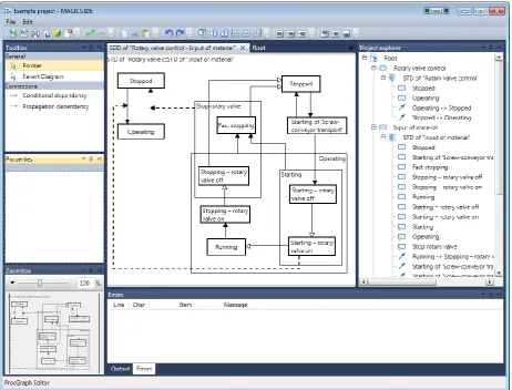
In this subsection we describe the results of the development of the industrial prototype tool suite, which is shown in Figure 2. We will discuss the requirements as well as the integration of the tool suite and the high-level architecture (with the emphasis on the model editor).
5.2.1. Requirements
For the development of the industrial prototype the same set of requirements as for the laboratory pro-totype was used (see Table 1). Only one requirement was added. It was labeled as R0.5, and defined with the following short description: ”The ProcGraph model must be saved in an XMI file, which can be imported into the EMF-based model repository”. The highest importance level (5) was assigned to this requirement.
The most important fact related to the requirements is that out of the 32 requirements 30 were fulfilled. The 2 unfulfilled requirements (R4.3.3 and R4.3.4) were intentionally left out, because it turned out that they are irrelevant for the users of the tool suite.
5.2.2. Integration of the support tools
During the integration of the new model editor with the existing components we used the integration on the model level, i.e., we used the standard XMI format, which is intended for model exchange. Another goal was integration at the runtime level, which means that the code generator can be invoked from within the model editor. In this way the tool suite would become a real integrated development environ-ment (IDE). This kind of integration was challenging because the new model editor was based on the .NET platform, which means that the already-existing model repository and the code generator are essentially running on the Eclipse platform. We found that there is a subset of the EMF and openArchitectureWare that can be used in stand-alone Java applications and is not directly dependent on the Eclipse platform. In C# it is possible to run a Java program so that a new system process is run in which the Java Virtual Machine is called, so that a certain Java program and its input parameters are specified. In our case we called two Java programs from the C# code. The first one imported the XMI model, which was created by the model editor, into the model repository, and the second one ran the code generator, which created the generated code. It was created in the folder that was defined in the input parameter.
The metamodels defined in the EMF framework cannot be used in .NET applications. A negative consequence of this is that the same metamodel has to be created in two different places, as well as a connection between them, over which we can transfer
models from the model editor in .NET to the model repository in EMF. All three components have to be manually maintained in order to guarantee the consis-tency. The connection was realized over an automatic XMI serialization. In practice this turned out to be a smaller problem than anticipated. The advantage of the new development method of the model editor was a smaller influence on the metamodel of the DSML, since it did not put constraints on the structure of the metamodel. This was not the case with the GMF, because of its implementation and the way of gene-rating the editors. Consequently, the implementation metamodel, which is used in the model repository and in the model editor, is the same as the general meta-model of the ProcGraph language.
5.2.3. Architecture
An important element that enables a flexible and efficient development of the model editor is the software architecture. During the definition of the software architecture of the ProcGraph model editor we wanted to build on the good ideas of the GMF framework, from which the most outstanding is the separation of the development into different models that define different viewpoints of the editor. Based on this we decided that the architecture must contain parts that cover the abstract syntax (i.e., metamodel), the concrete syntax, the syntactic mapping, the tools for the diagram manipulation and the graphical controls of the application.
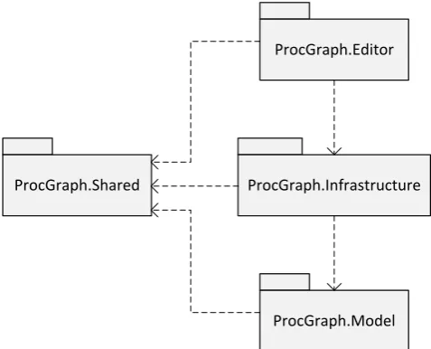
During the development we wanted to take advantage of the newer and, at the same time, well tested and powerful features of the .NET framework. Therefore, we decided to develop the editor as an application based on the WPF (Windows Presentation Foundation) technology. WPF is a subsystem of the .NET framework (introduced in version 3.0), which represents an alternative to the Windows Forms technology and is intended for Rich Client Applica-tions [37]. The architecture of the industrial prototype of the model editor is specified in Figure 3 and consists of four basic assemblies:
ProcGraph.Model contains the classes that represent the metamodel of the ProcGraph language. This assembly also defines the syntactical mapping of the DSML.
ProcGraph.Editor is a graphical user interface that is realized as a WPF application and uses the ProcGraph.Infrastructure.
ProcGraph.Infrastructure contains a set of controls for the visual elements (among others, also the concrete syntax) that are created based on the contents of the ProcGraph.Model assembly. ProcGraph.Shared contains the functionality that
Figure 3. High-level architecture of the industrial prototype of the model editor
6. The findings
In order to study the effects of the systematically chosen new development methodology for the indus-trial prototype, we carried out a comparison of the development of both prototypes. Based on this comparison, our experience and a literature overview we also drew a set of lessons learned.
6.1. A comparison of the prototypes
The comparison was carried out from three different perspectives, i.e., the requirements ful-fillment perspective, the usability perspective and the development process perspective.
6.1.1. Requirements perspective
From the requirements point of view the ful-fillment of the functional requirements was signi-ficantly more successful in the industrial prototype. We managed to realize the key requirements that were not realized in the laboratory prototype, because of which the development with GMF was discontinued. It turned out that with the .NET framework and the WPF subsystem the diagram synchronization was successfully implemented. This was not accom-plishable with the GMF framework, because of its complex and limited synchronization infrastructure. We also succeeded in implementing the overlapping super-states (R2.5), which was a very demanding task. The large quantity of relevant examples found on the World Wide Web, which showed the use of WPF for similar purposes, was very helpful. The large user base of the WPF subsystem as well as its extensive documentation were also important for implementing the overlapping super-states requirement.
6.1.2. Usability perspective
The industrial prototype tool suite has been used in laboratory experiments and for re-engineering
software in previous industrial projects. From the non-functional requirements perspective, the industrial prototype is superior in the areas of stability, responsiveness, usability, understandability, and user-interface intuitiveness. The main reason for the first two is the use of .NET instead of GMF and the Eclipse platform. The use of Scrum contributed to the remaining improvements, since intermediate versions of the prototype were delivered faster and showed more often to the users; therefore, their feedback was received faster and could be more easily reflected in the prototype. The end users, who were included in the testing, gave testimonials that they would be interested in using the industrial prototype in practice. The only drawback of the industrial prototype is its inability to show multiple diagrams of the edited ProcGraph model at the same time. This was possible in the laboratory prototype. In the industrial prototype this feature is missing, because the WPF subsystem does not support the correct rendering of two or more diagrams. However, this has not turned out to be problematic, because the users did not evaluate this as annoying or even so critical that the industrial prototype would be deemed as less useful.
6.1.3. Development process perspective
The development process of the industrial proto-type was more manageable and less demanding than the laboratory-prototype development approach. This was because it was not necessary to integrate auto-matically generated and manually written code and carry out a complex and partially manual process of regenerating the editor, even for the slightest change of the editor models, as was the case with GMF. It was also possible to use automatic unit testing, the positive effects of which are generally known. The agile Scrum method, which was used instead of a proprietary development method, based on the GMF framework, also had a positive influence on the manageability of the development. The implementation of ProcGraph’s
ProcGraph.Model ProcGraph.Infrastructure
ProcGraph.Editor
concrete syntax and the editing behavior were easier with the use of .NET and WPF than with the use of Eclipse and the GEF and Draw2D frameworks. Also, in general, the .NET framework turned out to be more mature and better documented.
6.2. Lessons learned
The analysis of the laboratory prototype develop-ment showed that the GMF framework was not the most suitable option for the realization of the ProcGraph model editor. We found that it is immature, complex, demanding to learn and incapable of ful-filling some important requirements. It has a number of constraints and problems and is not supported by a proper development process. Our experience can be generalized into the recommendation that the use of GMF should be discouraged for the development of a model editor for an arbitrary DSML with the following properties:
It consists of different diagrams that need to be synchronized.
It has diagrams that can contain overlapping super-elements. The overlapping areas contain shared sub-elements. In other words, these are diagrams in which the sub-elements can be contained in two or more immediate super-elements. An example of such diagrams is Venn diagrams. The topic of overlapping Statecharts was also discussed by Harel and Kahana [38].
Based on our experience from the development of the tool suite for the MAGICS methodology, we can claim that metamodeling tools are still a relatively immature technology, primarily the metamodeling tools, which are intended for the automatic generation of editors for visual or hybrid models. On the other hand, it has become clear that the theory of metamo-deling, with which we defined the abstract syntax of the DSML and automatic model repository generation based on this formalism, is mature. This is at least the case with the EMF framework, which turned out to be a very suitable tool. Another mature technology is the development of code generators based on code templates, in our case the openArchitectureWare framework. This and similar tools are based on an extensive experience gained in the field of language generators (e.g., ANTLR [39]),) and therefore work very well in practice.
Our experience cannot be directly generalized, because the ProcGraph language has a specific concrete syntax and we had some very specific requirements. This language could be classified as a complex DSML. Although the literature occasionally uses the term complex DSML (e.g., [7, 40, 41]), there is a lack of definition. We propose that one of the criteria to classify a DSML as a complex one is that with it models can be built that consist of a hierarchy of diagrams, which are instances of more than one diagram type. In general, the examples of DSMLs that are usually shown in the literature about metamodeling
tools are usually simple, real-life languages (e.g., a language for the domain of elevator controllers [29], a simplified Goal-oriented Requirement Language [42], and a language for risk analysis [43]) or artificial toy languages (e.g., a Simple Component-connector Lan-guage [44], a lanLan-guage for social networks [45], and the J2EE configuration language [46]). With such languages most metamodeling tools are sufficient during the task of model-editor generation. Most of these tools, however, are not able to sufficiently support the generation of model editors for complex DSMLs, which shows the immaturity of this techno-logy. In relation to these issues several interesting possibilities for future research arise, e.g., complex DSMLs could be studied, their features generalized and solutions proposed about how to support these features in specific metamodeling tools. Such research is beyond the scope of this paper; however, it would surely help the practitioners who are developing proprietary support tools for an arbitrary model-driven process based on a complex DSML.
Because of the immaturity and the lack of capabi-lities of the metamodeling tools it is recommended to consider the use of a traditional development approach to tool support development for MDE approaches. We recommend that the practitioners do this, especially if they are dealing with the development of a model editor for a complex DSML. The other support tools can still be realized with metamodeling tools, so that the development of the entire tooling then becomes a hybrid development. In the case that a traditional development approach is used, one has to carefully think about the flexibility and the separation of different parts of the DSML, as we have done during the definition of the architecture of the ProcGraph model editor. A few similar findings have been made in the area of debuggers [47] and test engines [48, 49]; therefore, this claim may be generalized to support tools for complex DSMLs.
should be 10 times higher than the one with the .NET framework, of course under the assumption that in all other regards the two approaches are equivalent in fulfilling the requirements. Despite some reports [24, 50, 51] about productivity increases with the use of the GMF framework, we did not find any sources that would contain quantitative data to support this. In the broader context, i.e., MDE paradigm Sprinkle, et al. [10] reported that in three different studies with the use of MDE a 3–10 times higher productivity was achieved. Another source [3] reports that the increase in the productivity is significantly smaller with the introduction of the MDE concept. Our experience also shows that the increase is strongly hindered by increasing the complexity of the used DSML and that the increase in the productivity by a factor of 10 with the use of GMF for complex DSMLs is very unlikely. This means that the traditional development of the model editor for complex DMSL is probably at least equally expensive as the development with GMF, and perhaps even cheaper. In our case we also had to take into account the higher cost of a distributed development with a company e.g., from Germany or the USA. Therefore, traditional development (with the .NET framework) was clearly a better alternative and was selected for the development of the industrial prototype of the model editor.
7. Conclusion
This experience report describes the “rocky road” to an industrial prototype tool that should support a MDE approach in the process control domain. This was especially demanding for the model editing part, because of the complexity of some language elements of the used graphical modeling language ProcGraph. On the basis of an analysis of the past development, in which a laboratory prototype had already been deve-loped, we decided not to use the metamodeling tools for the development of the model editor, which at the beginning seemed to be a natural direction. Instead, we decided to use a mature development technology (.NET framework) and an agile development process (Scrum). Without this decision it is very doubtful that the industrial prototype tool could even have been developed (i.e., key requirements would remain unfulfilled). The comparison of the laboratory and industrial prototype development showed that the selected development methodology substantially facilitated the development of the industrial prototype. Compared to the previous development effort a significant increase in the amount of implemented requirements and tool-suite reliability and usability was achieved.
Based on our experience we learned several lessons that might be useful to other MDE practi-tioners, especially the ones that provide support for complex modeling languages. One of the most impor-tant lessons is that for the development of model editors the traditional development approach should
not be easily rejected, especially when a visual or hybrid (i.e., visual and textual) model editor is needed. However, these findings are different from the majority of the reports in the literature and the common expectation of the MDE community, which means that this discrepancy should be investigated further in future research.
Acknowledgment
The support of the Slovenian Research Agency (ARRS) is gratefully acknowledged.
References
[1] D. C. Schmidt. Model-Driven Engineering. IEEE
Computer, 2006, Vol. 39, No. 2, 25-31.
[2] S. Kelly, J.-P. Tolvanen. Domain-Specific Modeling.
John Wiley & Sons, 2008.
[3] P. Mohagheghi, V. Dehlen. Where Is the Proof?-A Review of Experiences from Applying MDE in Industry. In: European Conference on Model Driven
Architecture: Foundations and Applications
(ECMDA-FA'08), Berlin, Germany, 2008, pp.
432-443.
[4] J. Hutchinson, J. Whittle, M. Rouncefield, S. Kristofferson. Empirical assessment of MDE in industry. In: 33rd International Conference on
Software Engineering (ICSE'11), Waikiki, Honolulu,
USA, 2011, pp. 471-480.
[5] P. Mohagheghi, W. Gilani, A. Stefanescu, M. A. Fernandez. An empirical study of the state of the practice and acceptance of model-driven engineering in four industrial cases. Empirical Software
Engineering, 2013, Vol. 18, No. 1, 89-116.
[6] J. Gray, K. Fisher, C. Consel, G. Karsai, M. Mernik, J.-P. Tolvanen. DSLs: the good, the bad, and the ugly. OOPSLA Companion '08. ACM, 2008, pp. 791-794.
[7] O. Semeráth, Á. Horváth, D. Varró. Validation of Derived Features and Well-Formedness Constraints in DSLs. Model-Driven Engineering Languages and
Systems. Springer, 2013, pp. 538-554.
[8] T. Lukman, G. Godena, J. Gray, M. Heričko, S. Strmčnik. Model-driven engineering of process control software – beyond device-centric abstractions.
Control Engineering Practice, 2013, Vol. 21, No. 8,
1078-1096.
[9] M. Colla, T. Leidi, M. Semo. Design and implemen-tation of industrial automation control systems: A survey. In: IEEE International Conference on
Industrial Informatics (INDIN'09), Cardiff, UK, 2009,
pp. 570-575.
[10] J. Sprinkle, M. Mernik, J.-P. Tolvanen, D. Spinellis. What Kinds of Nails Need a Domain-Specific Hammer? IEEE Software, 2009, Vol. 26, No. 4, 15-18. [11] B. Selic. The Less Well Known UML. Formal
Methods for Model-Driven Engineering. Springer,
Berlin Heidelberg, Germany, 2012, pp. 1-20.
[12] F. Noyrit, S. Gérard, B. Selic. FacadeMetamodel: Masking UML. Model Driven Engineering Languages
and Systems. Springer, 2012, pp. 20-35.
In: 4th Workshop on Development of Model-Driven
Software, San Sebastian, Spain, 2008, pp. 11-20.
[14] Object Management Group. UML Superstructure Specification Version 2.4.1., 2011.
[15] Object Management Group. Meta Object Facility: MOF Core specification, Version 2.0. 2006.
[16] M. Mernik, J. Heering, A. M. Sloane. When and how to develop domain-specific languages. ACM
Compu-ting Surveys, 2005, Vol. 37, No. 4, 316-344.
[17] M. Fowler, R. Parsons. Domain-specific languages.
Addison-Wesley Professional, 2010.
[18] S. Sendall, W. Kozaczynski. Model transformation: the heart and soul of model-driven software develop-ment. IEEE Software, 2003, Vol. 20, No. 5, 42-45. [19] S. Gérard. Papyrus UML. Accessed on 07.01.2014,
http://www.papyrusuml.org/.
[20] D. Neuendorf. Review of MagicDraw UML® 11.5 Professional Edition. Journal of Object Technology, 2006, Vol. 5, No. 7, 115-118.
[21] R. Vitiutinas, D. Silingas, L. Telksnys. Model-Driven Plug-in Development for UML Based Modeling Systems. Information Technology and
Control, 2011, Vol. 40, No. 3, 191-201.
[22] S. Pavalkis, L. Nemuraitė, R. Butkienė. Derived Properties: A User Friendly Approach To Improving Model Traceability. Information Technology and
Control, 2013, Vol. 42, No. 1, 48-60.
[23] T. Skersys, R. Butleris, K. Kapocius, T. Vileiniskis. An Approach for Extracting Business Vocabularies from Business Process Models. Information
Technology and Control, 2013, Vol. 42, No. 2,
178-190.
[24] R. C. Gronback. Eclipse Modeling Project: A Domain-Specific Language (DSL) Toolkit.
Addison-Wesley Professional, 2009.
[25] Á. Lédeczi, Á. Bakay, M. Maróti, P. Völgyesi, G. Nordstrom, J. Sprinkle, G. Karsai. Composing Domain-Specific Design Environments. IEEE
Computer, 2001, Vol. 34, No. 11, 44-51.
[26] M. Maurmaier. Leveraging model-driven develop-ment for automation systems developdevelop-ment. In: IEEE International Conference on Emerging Technologies
and Factory Automation (ETFA'08), Hamburg,
Germany, 2008, pp. 733-737.
[27] G. Godena. ProcGraph: a procedure-oriented graphi-cal notation for process-control software specification.
Control Engineering Practice, 2004, Vol. 12, No. 1,
99-111.
[28] T. Lukman, M. Mernik. Model-driven engineering and its introduction with metamodeling tools. In:
International PhD Workshop on Systems and
Control'08, Izola, Slovenia, 2008, pp. 1-6.
[29] C. Wienands, M. Golm. Anatomy of a Visual Domain-Specific Language Project in an Industrial Context. In: 12th International Conference on Model
Driven Engineering Languages and Systems
(MODELS'09), Denver, USA, 2009, pp. 453-467.
[30] J. Grundy, J. Hosking, W. B. Mugridge. Inconsis-tency management for multiple-view software develo-pment environments. IEEE Transactions on Software
Engineering, 2002, Vol. 24, No. 11, 960-981.
[31] I. Sommerville. Software Engineering. Addison
Wesley Publishing Company, 2006.
[32] B. Boehm, R. Turner. Balancing Agility and Discipline: A Guide for the Perplexed. Addison-Wesley
Professional, 2003.
[33] V. Vinekar, C. L. Huntley. Agility versus Maturity: Is There Really a Trade-Off? IEEE Computer, 2010, Vol. 43, No. 5, 87-89.
[34] K. Schwaber. Scrum development process. In:
OOPSLA Business Object Design and Implementation
Workshop, Austin, USA, 1995, pp. 10-19.
[35] N. B. Moe, T. Dingsøyr. Scrum and Team Effectiv-eness: Theory and Practice. Agile Processes in
Soft-ware Engineering and Extreme Programming.
Sprin-ger, Berlin Heidelberg, Germany, 2008, pp. 11-20. [36] E. Hossain, M. A. Babar, P. Hye-young. Using
Scrum in Global Software Development: A Systematic Literature Review. In: 4th IEEE International
Conference on Global Software Engineering
(ICGSE'09), Limerick, Ireland, 2009, pp. 175-184.
[37] L. Rising, N. S. Janoff. The Scrum software development process for small teams. IEEE Software, 2000, Vol. 17, No. 4, 26-32.
[38] D. Harel, C. Kahana. On statecharts with over-lapping. ACM Transactions on Software Engineering
and Methodology, 1992, Vol. 1, No. 4, 399-421.
[39] T. Parr. The Definitive ANTLR Reference: Building Domain-Specific Languages. Pragmatic Bookshelf, 2007.
[40] B. Bryant, J. Gray, M. Mernik, P. Clarke, R. France, G. Karsai. Challenges and directions in formalizing the semantics of modeling languages.
Computer Science and Information Systems, 2011,
Vol. 8, No. 2, 225-253.
[41] J. Johannes, M. A. Fernández. Adding abstraction and reuse to a network modelling tool using the Reuseware composition framework. Modelling
Foundations and Applications. Springer, 2010,
pp. 132-143.
[42] D. Amyot, H. Farah, J.-F. Roy. Evaluation of Development Tools for Domain-Specific Modeling Languages. System Analysis and Modeling: Language
Profiles. Springer, Berlin Heidelberg, Germany, 2006,
pp. 183-197.
[43] F. Seehusen, K. Stølen. An evaluation of the graphical modeling framework (GMF) based on the develop-ment of the CORAS tool. Theory and Practice of
Mo-del Transformations. Springer, 2011, pp. 152-166.
[44] D. S. Kolovos, L. M. Rose, S. B. Abid, R. F. Paige, F. A. C. Polack, G. Botterweck. Taming EMF and GMF Using Model Transformation. Model Driven
Engineering Languages and Systems. Springer, Berlin
Heidelberg, Germany, 2010, pp. 211-225.
[45] J. de Sousa Saraiva, A. Rodrigues da Silva. Evaluation of mde tools from a metamodeling perspective. Journal of Database Management, 2008, Vol. 19, No. 4, 21-46.
[46] S. Temate, L. Broto, A. Tchana, D. Hagimont. A High Level Approach for Generating Model's Graphical Editors. In: 2011 Eighth International
Conference on Information Technology: New
Generations (ITNG), Las Vegas, USA, 2011, pp.
743-749.
[48] T. Kos, T. Kosar, J. Knez, M. Mernik. From DCOM interfaces to domain-specific modeling language: A case study on the Sequencer. Computer Science and
Information Systems, 2011, Vol. 8, No. 2, 361-378.
[49] T. Kos, T. Kosar, M. Mernik. Development of data acquisition systems by using a domain-specific modeling language. Computers in Industry, 2012, Vol. 63, No. 3, 181-192.
[50] T. Buchmann, A. Dotor, B. Westfechtel. Model driven development of graphical tools: Fujaba meets
GMF. In: International Conference on Software and
Data Technologies (ICSOFT'2007), Barcelona, Spain,
2007, pp. 425-430.
[51] A. Evans, M. A. Fernández, P. Mohagheghi. Expe-riences of Developing a Network Modeling Tool Using the Eclipse Environment. In: 5th European Conference
on Model Driven Architecture - Foundations and
Applications (ECMDA-FA'09), Enschede, The
Netherlands, 2009, pp. 301-312.
![Figure 1. A scheme of the MAGICS approach [8]](https://thumb-us.123doks.com/thumbv2/123dok_us/8765718.1754322/4.595.97.484.445.748/figure-scheme-magics-approach.webp)