0 INTRODUCTION
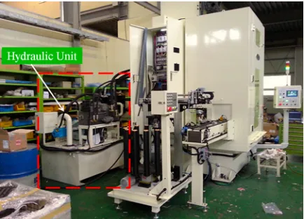
Broaching is widely used in industrial applications to machine various features on internal surfaces, including key ways, noncircular holes, and fir-tree slots on turbine discs. This operation has several benefits when machining conditions are appropriately selected, including high productivity, compatible surface integrity, and ensured geometrical accuracy. Unfortunately, conventional broaching machines, which use a hydraulic system, have many disadvantages, such as noisy operation, excessive energy consumption, low productivity, and large footprint required for installation (Fig. 1). The hydraulic pump is the dominant source of noise and consumes 60 % to 80 % of the total energy. Therefore, the development of a new broaching machine without a hydraulic system is desirable.
The optimization of broaching has attracted
the attention of many researchers. Klocke et al. [1]
investigated the effects of cutting-edge geometries on the process forces, chip formation, and tool wear mechanisms. The surface quality was analysed under
various machining parameters in real processing time [2] to [4]. However, no one has investigated the interaction between the mechanical structure of the machine and its controller under working conditions. Consequently, an effective approach to predict machine performance before physical prototyping is urgently needed.
Usually, a physical prototype is used in the design stage to produce and evaluate new machine models.
However, this method is slow and expensive [5].
Fortunately, many publications have indicated that virtual prototyping approaches using well-defined material properties, numerical models, and controllers can accurately analyse, simulate, and investigate real machine behaviour. Dai et al. [6] developed a virtual prototype model for a remotely operated seabed tracked vehicle to optimize and support the control system without the need for expensive hardware prototyping. Likewise, virtual prototyping of industrial equipment has been proposed to investigate dynamic behaviour in the initial stage [7] to [9]. All these studies demonstrated that virtual prototyping
Development of a Servo-Based Broaching Machine
Using Virtual Prototyping Technology
Park, H.S. – Dang, D.V. – Nguyen, T.T.
Hong Seok Park1 – Duc Viet Dang1,* – Trung Thanh Nguyen2
1University of Ulsan, School of Mechanical and Automotive Engineering, South Korea 2Le Quy Don Technical University, Faculty of Mechanical Engineering, Viet Nam
Predicting machine tool performance at the design stage is one way to resolve the time issue and achieve cost savings. The objective of this paper was to develop a new non-hydraulic broaching machine using a servo motor, ball screw, and roll element linear guide using virtual prototyping technology. First, we developed a multi-body simulation model (MBS) of a servo-based broaching machine to investigate its dynamic behaviour. Then, an adaptive sliding mode proportional-integral-derivative (PID)-based controller (ASMPID) was proposed to conduct the broaching process. We then performed a co-simulation between the mechanical structure and virtual controller to investigate the ram body trajectory and identify the optimal control parameters. Finally, we manufactured a prototype machine to evaluate the simulation results and determine the benefits of the new system. Our results indicated that the proposed model, which includes a mechanical structure and intelligent controller, effectively improved broaching machine design. Therefore, this work is expected to improve the prototyping efficiency of new broaching machines.
Keywords: broaching machine, servo motor, ball screw, virtual prototype technology, multi-body simulation, adaptive sliding mode control
Highlights
• A new broaching machine that uses a servo motor, ball screw, and roll element linear guide has been developed to replace hydraulic components.
• A multi-body model of the new broaching machine that includes a control system model was established to generate a virtual prototype machine.
• The proposed adaptive sliding mode PID-based controller effectively eliminates external disturbances in the non-linear system during the broaching process.
technology is a powerful tool for simulating and optimizing machine tool characteristics.
Fig. 1. A conventional broaching machine using a hydraulic unit
To overcome the limitations of hydraulic systems, we developed a new broaching machine using a servo motor, ball screw, and roll element linear guide based on virtual prototyping technology. We found that the interaction between the mechanical structure and the controller, along with external disturbances in processing time, contributed to the machine tool efficiency. Consequently, the development of a robust approach for describing machine tool behaviour and generating optimal control parameters is an important area of research.
In this paper, the scientific methodology used to resolve these issues is first introduced. Next, the concept for a new broaching machine and mechanical model are presented. The multi-body rigid-flexible model and control system are then described. Subsequently, the co-simulation results of the virtual broaching machine and the physical prototype are discussed. Finally, we draw conclusions and suggest future research.
1 RESEARCH METHODOLOGY
The framework proposed for the development of a new broaching machine based on a multi-body simulation (MBS) model and an intelligent virtual controller is shown in Fig. 2. We formulated the problem and designed the mechanical structure based on specific requirements. Next, an MBS model of the new machine was developed to represent the actual mechanical system and to determine the body relationships, degrees of freedom, space missions, joint types, and geometric constraints in an integrative model. Subsequently, a dynamic simulation was
conducted to identify the machine tool behaviour and stress distribution. Then, an intelligent controller was designed and integrated with the mechanical model to construct a virtual prototype of our new broaching machine. A co-simulation was performed to evaluate the controller functionality. Finally, the physical machine was manufactured to perform broaching operations and verify that the design requirements were met.
2 CONCEPTUAL DESIGN OF A SERVO-BASED BROACHING MACHINE
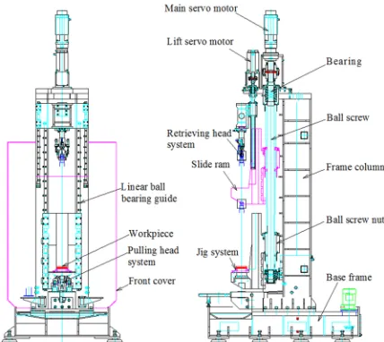
A servo-based broaching machine was developed based on a 7.5-ton hydraulic version currently used to manufacture the internal surface of automotive components such as hubs, inner races, and sleeves (Fig. 3 [10]). The machine has five key systems: a feed drive, controller, slider, frame, and tool brush. The configuration of the servo-based broaching machine is shown in Fig. 4, and the specifications are listed in Table 1. In the proposed concept, the servo-driven axis and ball screw are mounted on the machine frame. The sliding system, which includes the table lift, tool brush, and linear guide, performs the broaching motions. The closed-loop principle is applied to control the feed driving movements. As a result, the new servo-based broaching machine can offer high productivity, appropriate stiffness, improved accuracy, noise reduction, and a smaller footprint than the traditional one can.
The working principle of the servo-based broaching machine can be divided into the following steps:
Step 1: A work piece is transferred to the ram body and is clamped using the jig system.
Step 2: The retrieving head-system-mounted tool moves down to perform the broaching process. This motion is conducted with the support of the lift servo motor, ball screw, and linear ball-bearing guide.
Step 3: The tool is engaged by the pulling head system, and the ram body is then moved to the highest position required for broaching the desired shapes. The retrieving head system is moved after the machining cycle is complete.
Step 4: The ram body is moved to the bottom of the machine, and the machined part is removed. The retrieving head system is moved down, and a new machining cycle can then begin.
3 DEVELOPMENT OF A MULTI-BODY MODEL
3.1 The Equations of Motion for a Flexible Multi-Body System
A multi-body dynamic model can be created using variations of mechanical principles, such as the energy conservation law, the Newton-Euler equation, the Lagrange equation, the Hamilton principle, and the Kane equation. Among these approaches, the Lagrange equation has been widely applied to build
forward or inverse kinematics model [11] and [12].
A flexible body can be considered as a collection of nodes in a finite element model, and deformation can be seen as a linear superposition of mode shapes.
Table 1. Specifications of the new broaching machine
Specifications Value
Cutting power [N] 80000
Main stroke [mm] 1235
Lift stroke [mm] 700
Cutting speed [mm/s] 100
Return speed [mm/s] 200
Main servo motor [kW] 14
Lift servo motor [kW] 4
Fig. 3. The main machined parts in the new broaching machine
Fig. 4. The configuration of a servo-based broaching machine
Fig. 5 illustrates the position of a particle P 0
i and
a node on flexible body i, where point Pi is the new
position of node P
0
i according to vector u f
i when
body i is deformed. The global reference frame of
body i is represented using the Cartesian coordinates
x, y, and z.
r
(
x y z)
is the origin vector for the position of the local reference coordinate system (xi, yi, zi) for body i. Its direction, expressed in Eulerangles, is π=
(
ϕ θ ψ)
. The deformation of theflexible body depicted by generalized coordinates is
q q q qm
T
=
{
1 2 ...}
.Fig. 5. Location and orientation of points in a flexible body
Therefore, the generalized coordinates of the flexible body can be expressed as:
ξ={x y z,ϕθψ,q i( = ,...,m)} ={ π q},
i 1 T
r
(1)where m is the number of model coordinates. The
location vector of node Pi in a global reference frame
rPi r A ui r A u u p
i i i
f i
= + = + ( + ),
0 (2)
where Ai denotes the transformation matrix from the
local coordinate system to the global coordinate system, which is expressed in terms of four Euler parameters. up
i is the position vector of point Pi given the body’s local coordinate system. ui
0 is the position
of point P
0
i in a non-deformed state of body i in a
local coordinate system. uif is the direction vector of
point Pi on a deformed body with respect to point P 0
i
on a non-deformed body.
uif = Φpq. (3)
Φp is the supposed deformation mode matrix for
the motion’s degree of freedom on node Pi. The
velocity of node P 0
i can be expressed as:
vp I A u u B Ai i
f i i p = −[ ( + ) ] ,
0 Φ ξ (4)
where I and the tilde symbol present the identity
matrix and skew symmetric matrix, respectively.
Matrix B is defined as a first-order derivative of a
Eulerian angle relative to time or the angular velocity transition matrix. Consequently, the kinetic energy in the flexible body can be expressed as:
T= T dV = TM
∫
12
1
2
ρν ν ξ ( ) ,ξ ξ (5)
where ρ and M are the mass density and flexible-body mass matrix, respectively. The potential energy of the flexible body is:
W W= g( )ξ +1ξTKξ,
2 (6)
where K is a generalized stiffness matrix corresponding
to mode coordinate q. Damping force depends on the
generalized modal velocity and can be deduced from:
Γ =1
2q Dq
T , (7)
where G and D represent the energy dissipation
function and constant symmetry matrix, respectively. Due to interactions between the components, the kinetic equation can be inferred from [12]:
d dt
L L T Q
∂ ∂ −∂∂ +∂∂ +∂∂ − = = ξ ξ ξ ψ ξ λ ψ Γ 0 0
, (8)
where L = T – W, ψ, λ, and Q are the Lagrange
term, constraint equation, Lagrange multiplier, and generalized forces, respectively.
Substituting the calculated values for T, W and
G into Eq. (8) gives the flexible body differential
equation of motion using the Lagrange multipliers method:
M M M K f
D Q T g T ξ ξ ξ ξ ξ ξ ψ ξ λ + − ∂ ∂ + + + + + ∂ ∂ = 1 2
, (9)
where fg , ξ, and ξ are the gravity force and first and
second derivatives of the generalized coordinates of the flexible body, respectively.
3.2 Modelling the Multi-Body Rigid-Flexible System of the New Broaching Machine
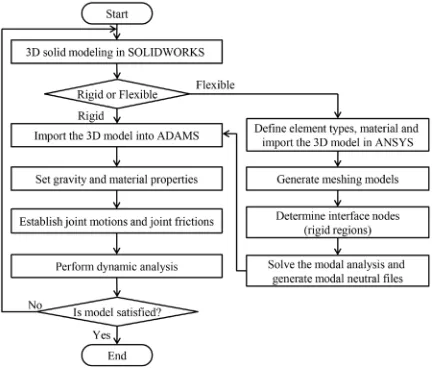
The framework for the rigid-flexible coupling dynamics analysis is illustrated in Fig. 6. First, the 3D machine model with component characteristics was designed based on the conceptual design. The machine tool parts are divided into two key bodies, rigid and flexible, depending on their working functionalities. ANSYS software was used to discretize the components into a small grid and generate modal neutral files. Next, the rigid and flexible bodies were imported into the ADAMS software by means of a Parasolid file in the *.x_t format and a modal neutral file in the *.mnf format, respectively. The driving modes of the joints were then specified for predetermined motions. Finally, we performed a dynamic simulation to evaluate the characteristics of the conceptual design.
Fig. 6. Flowchart modelling the rigid-flexible coupling
The ram body deforms under the working conditions that occur during processing. Therefore, it is necessary to model this component as a flexible body. The CAD model of the ram body was thus transferred to the FA software ANSYS. The material properties, unit type, unit attributes, and mesh parameters were defined before meshing. Two connection points in ANSYS were specified to generate the relationships between the flexible body and other components. The modal neutral file (*.mnf file) was generated using the interface between ANSYS and ADAMS. The other components (base frame, cutting tool, and frame column) were modeled as rigid bodies due to their low deformation during processing and were assigned mass and inertia matrices as illustrated in Table 2.
Fig. 7. Rigid-flexible coupling model
Table 2. Parameter values used to model the broaching machine
Parts Material Mass [kg] Ixx
[kg∙m2] Iyy
[kg∙m2] Izz
[kg∙m2]
Cutting tool SKH-55 35.4 4.661 4.661 0.02 Workpiece SCr420H1 4 0.007 0.007 0.013 Rambody Steel 897.2 99.922 106.038 32.5 Frame Steel 3559 5077.47 5093.63 452.47 Base Cast-Iron 2313 1005.525 633.586 1518.337
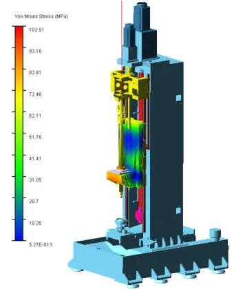
The simulation of the rigid-flexible model was conducted to investigate the machine behaviour under working conditions using: 1000 steps in 20 s intervals. The Von Mises stress distribution in the ram body during processing is illustrated in Fig. 8. Detailed
information about the 10 maximum stress nodes is shown in Table 3. The maximum stress is less than the allowable value, and the ram body meets the strength requirement. In other words, the designed machine is safe in terms of dynamic behaviour. Therefore, the developed model can be used to simulate, analyse, and validate the machine functionality.
Fig. 8. Stress distribution in the new broaching machine
Table 3. Details associated with the maximum stress on the ram body
Hot
spot Stress [MPa] Node Time [s] [mm]X [mm]Y [mm]Z 1 103.515 3324 1.8 -1806.36 489.718 -76.8091 2 99.0346 49 1.8 -1841.61 738.663 -399.309 3 98.0287 50 1.8 -1818.6 730.289 -399.309 4 97.6758 51 1.8 -1794.12 730.289 -399.309 5 93.0629 1196 1.8 -1951.36 423.195 -174.94 6 91.8174 765 1.8 -1961.36 418.86 -168.451 7 91.2342 1174 1.8 -1951.36 410.812 -168.404 8 89.9963 711 1.8 -1941.36 418.86 -168.451 9 89.845 52 1.8 -1771.11 738.663 -399.309 10 88.9793 53 1.8 -1752.35 754.401 -399.309
4 DEVELOPMENT OF AN INTELLIGENT CONTROLLER
4.1 Controller Design
gain KD. Furthermore, self-tuning controller gains can
improve potential applications of the PID control [13]
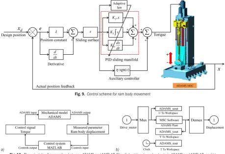
and [14]. In addition, the sliding mode control (SMC) is a popular strategy to deal with uncertain control systems [15] to [17]. The main advantage of the SMC method is its robustness against parameter variations and external disturbances. Therefore, combining an adaptive SMC with a PID controller (ASMPID) is an intelligent choice for updating PID gains and adapting to non-linear systems [18] and [19]. Here, we propose an ASMPID controller to investigate the ram body position of a servo-based broaching machine (Fig. 9).
4.2 Interaction between the Mechanical Model and Control System
The mechanical structure and control system communicate through an exchange of state variables. In this work, the control design was developed based on ADAMS/Control and MATLAB/Simulink, as depicted in Fig. 10a. The input and output signals represent the main servo motor torque and ram body position, respectively. These parameters were first defined in the ADAMS model to generate the state variable. After that, the virtual mechanical model was exported to the MATLAB/Simulink environment to complete the interaction (Fig. 10b). As mentioned above, the new broaching machine was considered to be a system with a single input and output. The state-space equation for the ram body displacement can be expressed as follows:
x t x t
x t f X b X u d t
1 2
2
( ) ( ),
( ) ( ) ( ) ( ),
=
= + + (10)
where X =(x x, )T
1 2 is a state variable vector that
represents the position of the ram body. f(X ) and b(X ) are nonlinear functions. d(t) is the bounded lumped disturbance, including parameter variations and external disturbances, u represents a control signal.
As shown in Eq. (10), the sliding surface can be defined as:
s e= + λe, (11)
where e = xd – x, and xd, x, and λ are the desired
position, measured position, and positive constant, respectively.
Substituting x t2( )=x in Eq. (11), gives
s x= d− f X( )−b X u d t( ) − ( )+λe. (12)
The control effort u of the PID controller is
determined as:
u
b X x f X d t e AB
PID = d− − + = + 1
( )
[ ( ) ( ) λ] ε, (13)
where A K K K=[ P I D], B s s ds=[
∫
dt]T, and ε is theappropriate error.
The control signal u of the controller is
determined as:
u u= PID+uh=AB u + h, (14)
where A K K K=[ P I D] represents the estimated
values of vector A, and uh is the signal of the auxiliary
controller.
Substituting Eq. (14) into Eq. (12) yields
s x f X b X AB u d t e
b X AB b X b X u
d h h = − − + − + = = + − ( ) ( )[ ] ( ) ( ) ( ) ( ) , λ
ε (15)
where A A A= − is the estimation error.
To prove the stability of the system, we used a Lyapunov function:
V=1s + A 2
1
2
2 2
γ . (16)
The derivative of Eq. (16) yields:
V s s A A
s b X AB b X b X u A A
sb X B
h
i i i
i = + = = + − + = = + 1 1 1 γ ε γ ( ( ) ( ) ( ) ) ( ( )
γγ A A sb X ε b X u sh
i
) + ( ) − ( ) ≤0. (17)
From Eq. (17), we have: (sb X B( ) +1 A)=0.
γ
i
Hence, Ai= − = −γAi sb X B( ) .
The three PID gains (KP, KI, and KD) are updated
on-line by the following adaptive laws:
K sb X s K sb X s K sb X ds
dt
P I
t
D
i =γ ( ) ,i =γ ( )
∫
,i =γ ( ) .0
(18)
Considering Eq. (17): V sb X= ( )ε−b X u s( ) h ≤0.
With the auxiliary controller, uh = η sgn(s); the sign
function is:
sgn( )s .
if s if s if s = > = − < 1 0 0 0 1 0 (19)
Therefore, we have:
V sb X b X s s
sb X b X s b X s
= − ≤
≤ − < − <
⇒ >
( ) ( ) sgn( )
Eq. (17) proves that the sliding surface is stable. The control torque of the main servo motor in the new broaching machine is shown in Eq. (14).
5 SIMULATION RESULTS
We performed a co-simulation that integrated the MBS model and the ASMPID controller. The tracking performance of the ram body is shown in Fig. 11a, in which the reference value (REF) was derived based
on the ram body trajectory. The simulation results revealed that the overshoot and settling time were near zero. Furthermore, the steady state error was satisfied with stable control criteria, and external disturbances were eliminated. Additionally, the ram body velocity was close to the design specification, as shown in Fig. 11b. Therefore, the proposed ASMPID controller is a robust approach to optimizing system parameters and eliminate disturbances.
Fig. 9. Control scheme for ram body movement
a) b)
Fig. 10. The principle of connection between ADAMS and MATLAB/Simulink; a) inputs and outputs in ADAMS and MATLAB, and b) interactions between the mechanical structure and controller
a) b)
6 PHYSICAL PROTOTYPING
The hardware for the new broaching machine was developed based on the 3D CAD model, and the results are described in Sections 3 and 5. The base frame, frame column, and ram body are illustrated in Fig. 12. We selected a THK ball screw (HBN10025S-7.5RRG2 +3055LC5) for its high load capacity, low torque fluctuation, low noise, and low long-term maintenance (Fig. 13a). The permissible axial force is approximately 179 kN to ensure rigidity under broaching forces. The linear guide has balls that roll in four rows, LM rails, and an LM block (model SHS45LR4KKHHC0E+2460LPI) to replace the traditional sliding guides (Fig. 13b). The main servo (A06B-0275-B410 with 14 kW power) generated the ram body movements, and the tool lift servo motor (A06B-0247-B400 with 4 kW) controlled the broaching tool motions. The machine controller is implemented using the algorithm proposed in Section 4.
a) b)
Fig. 12. Prototyped mechanical parts; a) machine frame, and b) ram body
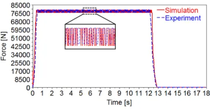
The broaching process was conducted to verify the simulation results in terms of the ram body velocity and broaching forces, as illustrated in Fig. 14. Moreover, the noise level and product quality also were investigated in order to verify the machine performance. The results indicate that the new broaching machine adequately meets the quality criteria and design specifications (Table 4). The
operating noise decreased by approximately 29 %, and the required working floor area decreased by about 30 % compared to the hydraulic-driven machine. Furthermore, the product quality criteria, including perpendicularity, concentricity, and true position, improved by around 49 %. The broaching force tested in the processing time is shown in Fig. 15. The small error between the simulation and experimental results demonstrates that the proposed approach is feasible and can be effectively used in machine tool design.
a) b)
Fig. 13. Components purchased for the machine; a) ball-screw, b) linear guide
Fig. 14. Physical prototype of the new broaching machine
Table 4. Experimental confirmation
Performance specifications Conventional machine Desired values in the machine Measured values Standard Co-axiality of the broach tool [mm] 0.05 0.04 0.03 KS B ISO 6779
Broaching speed [mm/s] 135 100 100 Test report
Return speed [mm/s] 235 200 200 Test report
Machine noise [dB] 80 60 56.9 KS I 5004
Broaching force [N] 100000 80000 81800 Test report
Perpendicularity of the part [mm] 0.08 0.06 0.042 KS B ISO 6779
Concentricity of the part [mm] 0.08 0.06 0.044 KS B ISO 6779
Fig. 15. Broaching force in processing time
7 CONCLUSIONS
In summary, this work presented the development of a new broaching machine based on an MBS and the implementation of modern control technology. The MBS model was developed to investigate the machine dynamic behaviour as a function of processing time. ASMPID was proposed and integrated into the synthesis model. The co-simulation was performed to investigate the dynamic machine tool behaviour and to obtain the optimal control parameters for eliminating system disturbances. The prototyped machine was implemented to conduct the broaching process and evaluate the simulation results. The following conclusions can be drawn from this investigation. 1. Based on conceptual ideas, a new broaching
machine was developed using a servo motor, ball screw, and roll element linear guide.
2. The simulation results indicate that the virtual prototyping model is safe in terms of dynamic behavior, satisfies the specifications, and has stable control criteria.
3. The ASMPID controller effectively eliminates external disturbances in this non-linear system during the broaching process.
4. The experimental results show that the
new broaching machine can eliminate the disadvantages of a traditional machine and increase the product quality.
8 ACKNOWLEDGEMENTS
This work was supported by an Institute for Information & Communications Technology Promotion (IITP) grant funded by the Korean government (MSIP) (B0101-16-1081, Development of ICT-based software platform and service technologies for medical 3D printing applications).
9 REFERENCES
[1] Klocke, F., Vogtel, P., Gierlings, S., Lung, D., Veselovac, D. (2013). Broaching of Inconel 718 with cemented carbide. Production Engineering, vol. 7, no. 6, p. 593-600,
DOI:10.1007/s11740-013-0483-1.
[2] Schulze, V., Zanger, F., Krauße, M., Boev, N. (2013). Simulation approach for the prediction of surface deviations caused by process-machine-interaction during broaching. Procedia CIRP, vol.8, p. 252-257, DOI:10.1016/j.procir.2013.06.098.
[3] Kishawy, H.A., Hosseini, A., Moetakef-Imani, B., Astakhov, V.P. (2012). An energy based analysis of broaching operation: Cutting forces and resultant surface integrity. CIRP Annals - Manufacturing Technology, vol. 61, no. 1, p. 107-110.
DOI:10.1016/j.procir.2013.06.098.
[4] Zanger, F., Boev, N., Schulze, V. (2014). Surface quality after broaching with variable cutting thickness. Procedia CIRP, vol. 13, p. 114-119, DOI:10.1016/j.procir.2014.04.020.
[5] Mandić, V., Ćosić, P. (2011). Integrated product and process development in collaborative virtual engineering environment.
Technical Gazette - Tehnički vjesnik, vol. 18, no. 3, p. 369-378.
[6] Dai, Y., Zhu, X., Chen, L.S. (2016). A mechanical-hydraulic virtual prototype co-simulation model for a seabed remotely operated vehicle. International Journal of Simulation Modelling, vol. 15, no. 3, p. 532-541, DOI:10.2507/ IJSIMM15(3)CO11.
[7] Zivanovic, S., Glavonjic, M., Milutinovic, D., (2015). Configuring a mini-laboratory and desktop 3-axis parallel kinematic milling machine. Strojniški vestnik - Journal of Mechanical Engineering, vol. 61, no. 1, p. 33-42, DOI:10.5545/sv-jme.2013.1619.
[8] Dai, Y., Pang, L., Chen, L., Zhu, X., Zhang, T. (2016) A new multi-body dynamic model of a deep ocean mining vehicle-pipeline-ship system and simulation of its integrated motion. Strojniški vestnik - Journal of Mechanical Engineering, vol. 62, no. 12, p. 757-763, DOI:10.5545/sv-jme.2015.3211.
[9] Tesic, Z., Stevanov, B., Jovanovic, V., Tomic, M., Kafol, C. (2016). Period batch control - a production planning system applied to virtual manufacturing cells. International Journal of Simulation Modelling, vol. 15, no. 2, p. 288-301, DOI:10.2507/ IJSIMM15(2)8.337.
[10] Korea Broach Manufacture Corporation. (2017). from http:// www.broachmc.co.kr/, accessed on 2016-10-02.
[11] Ambrósio, J.A.C., Gonçalves, J.P.C. (2001), Complex flexible multibody systems with application to vehicle dynamics. Multibody System Dynamics, vol. 6, no. 2, p. 162-182,
DOI:10.1023/A:1017522623008.
[12] Shabana, A.A. (2014). Dynamics of Multibody Systems, 4th ed., Cambridge University, Cambridge.
[13] Guclu, R. (2006). Sliding mode and PID control of a structural system against earthquake. Mathematical and Computer Modelling, vol. 44, no. 1-2, p. 210-217, DOI:10.1016/j. mcm.2006.01.014.
[15] Wang, W., Yi, J., Zhao, D., Liu, D. (2014). Design of a stable sliding-mode controller for a class of second-order underactuated systems. IEE Proceedings - Control Theory and Applications, vol. 151, no. 6, p. 683-690, DOI:10.1049/ ip-cta:20040902.
[16] Young, K.D., Utkin, V.I., Özgüner, Ü., (1999). A control engineer’s guide to sliding mode control. IEEE Transactions on Control Systems Technology, vol. 7, no. 3, p. 328-342,
DOI:10.1109/87.761053.
[17] Zinober, A.S.I. (1994). Variable Structure and Lyapnuov Control, Springer-Verlag, Berlin, DOI:10.1007/BFb0033675.
[18] Chang, W.-D., Yan, J.-J. (1994). Adaptive robust PID controller design based on a sliding mode for uncertain chaotic systems. Chaos Solitons & Fractals, vol. 26, no. 1, p. 167-175,
DOI:10.1016/j.chaos.2004.12.013.