2017 2nd International Conference on Artificial Intelligence and Engineering Applications (AIEA 2017)
ISBN: 978-1-60595-485-1
A Method Based on Multi-signal Flow Graph Model
for Disassembly and Assembly Process Simulation
HUIRU LI and KE LIANG
ABSTRACT
Maintenance procedure simulation of disassembly and assembly is an important way to record trouble shooting, applying it in the field of maintenance training will benefit the air crew to improve their skill any time they want. Because of the shortage of disassembly and assembly modeling about the whole process simulation, we build matrix relations of tool flow, parts relation flow and assembly and disassembly process flow, then build the whole process simulation model about troubleshooting. Applying the method in the operation of temperature fault of afterward cargo compartment, and proves the method reasonable and effective for disassembly and assembly simulation.
KEYWORDS
Maintenance; Disassembly and assembly Simulation; multi-signal flow graph; Disassembly and assembly information propagation hierarchical graph.
INTRODUCTION
Setting up maintenance training courses in maintenance simulation platform, which is a convenience way for training [1]. Aircraft component maintenance disassembly and assembly (D&A) process is an important part in the training, D&A process simulation can enables trainees in the absence of the real object, at the same time, maintenance training plays an important role in reducing maintenance cost. many difficulty and key courses can be operated many times they want. Now most (D&A) process simulation models for specific component, rather than the whole troubleshooting process of D&A (fault phenomena, determine the point of failure, troubleshooting), lacking the study of the whole dismantling process [2-4].
Multi-signal flow diagram can descript the whole process of maintenance modeling. In this paper, multi-signal flow graph was used to model, TSM (Trouble Shooting Manual) was used to get the point of failure information.
Set up matrix relations tool flow, component relationship, and D&A process flow about multi signal flow graph model. Through data collection, we can simulate the whole process of D&A , Applying the method in the operation of temperature fault of afterward cargo compartment, and proves the method reasonable and effective for disassembly and assembly simulation.
_________________________________________
MAINTENANCE SIMULATION PROCESS
The whole process of maintenance D&A.
The aircraft cockpit was installed multifunction display assembly---MCDU (Multi-functional Control and Display Unit), which can detect the fault information of aircraft computers, sensors, detectors and other equipment terminals. According to maintenance manual AMM (aircraft maintenance manual), we can locate the component that caused the system failure. And then implement the D&A operations, exclusion the fault, final results will be presented on the MCDU.
Simulation constitution
We simulate the maintenance D&A process, which include the fault information of the component, the fault information on MCDU and D&A process. In the maintenance D&A process, considered component fault, MCDU showing fault, confirming the fault component, completing disassembly of fault components, maintenance computer feedback to MCDU. Through the process we can complete the troubleshooting simulation. The D&A information flow contained D&A process modeling, parts—parts information flow, parts –tool flow, the D&A hierarchical information flow.
MAINTENANCE D&A PROCESS SIMULATION MODEL
The D&A process simulation modeling including multiple signal flow graph model, parts—parts information flow matrix, parts –tool flow matrix, the D&A hierarchical information flow matrix.
Signal Model
Fault information, to be D&A components, directed graph consist the three constituent elements of the multi-signal model [6]. In this model, fmrepresented D&A components (m = 1,2 ... i; i is the total number of individual component),Whenfm is 1, it indicates that the component is installed; When fm is 0, indicating that the component has failed or is in the process of D&A operation. Directed graph can linked every D&A step.
In the maintenance D&A multi signal flow graph, the point of fault is predictable. Simulate the real process of maintenance operation, the first is to confirm the fault (see MCDU information) ,read the fault number.
Check the fault acknowledgment location by manual TSM (Trouble Shooting Manual) of ECAM chapters. According to the information provided by TSM, do tests on MCDU. This article relates to simulation dismantling information. Just do the information flow simulation about the fault component on MCDU, not for all information on MCDU. According to test results, determining the faulty component, disassembling operation, troubleshooting.
Tools - Removing correlation matrix
Tools - Removing correlation matrix can be described as TP[tpij m n] * :
Among them, the bank represents the fault element, column represents D&A. Row vector represent the information of the tool which used to operate the parts of components, denoted Ta[t ta1, a2,,tab,]; Column vector represents the information of location about the removable components, denoted [ 1, 2, , ,]T
a a ab
Ta t t t ;
Correlation matrix TP may be obtained by reachability algorithms. To start from the peripheral element, search along the disassembly parts by multi-signal model, then reach the node, at this time, the corresponding correlation matrix elements of the value is"1" ; on the contrary, the value is"0".
Parts - Parts correlation matrix
This matrix shows the information flow between the associated parts.
*
[ ]ij m n PP p ,:
If a component consist of m parts, its Parts - Parts correlation matrix can be obtained from the adjacency matrix Q: PP Q Q2 Qm. Adjacency matrix Q can express the relationship between the parts which can structure the component,
denoted Q[ ]qij m n* .
The removing information adjacency matrix Q, can be obtained from the multi-signal flow graph model." m
Q " indicates m-th power of the "0-1" matrix, "+" indicates a Boolean matrix logical sum operation.
D&A hierarchical matrix
In part - parts association matrix, if elements in [ 1 , 2 , ,]T m m nm
Pm p p p are not all
zero, there is interdependence among the parts; If the elements in
1 , 2 , , [ ]T
m m nm
Pn p p p are all 0, it indicates that there is no interdependence among
the parts. Calculation Pmand Pn, the largest number of non-zero elements (ie strike
rank matrix) inPn, namely the number of D&A levels. The first non-zero element
inPm is the source node, namely a node in the first layer of disassembly.
D&A process simulation is from the lower level to the higher level, no priorities among the same level. Complete all the D&A, pass the information to the signal flag [4].Maintenance computer receives signals, then troubleshooting information presented on MCDU.
SIMULATION EXAMPLE
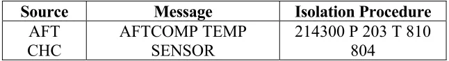
TABLE 1. Fault information about TEMP SENSOR.
Source Message Isolation Procedure
AFT CHC
AFTCOMP TEMP SENSOR
214300 P 203 T 810 804
Afterward cargo compartment temperature sensor
Afterward cargo compartment temperature sensor(13HC)is the important component in the air condition system, which can control the temperature. It uses the APU piping hot air and cooler air from afterward cabin to adjust cabin temperature. If the inlet temperature sensor fails, MCDU gets information from maintenance computer.
Maintenance D&A process simulation
According to A320 troubleshooting manual, get the fault information about the afterward cargo compartment temperature sensor. Shown in table 1.
We can set up fault information through maintenance computer, the fault SOURCE is in the AFT CHC, the test results shown on MCDU is AFTCOMP TEMP SENSOR, we can locate troubleshooting task isolation procedure number 214300 -810-804, then use TSM to find the maintenance operation task AMM 21-43-15-000-001.
This process is divided into four steps: first cockpit preparation operation, second preparation platform tools, third approaching the component. The second and third steps relate to the space transfer, we focus on the third step. The forth refer to the disassembly and assembly of parts.
Analysis the relationship between tool and each step, get tool – D&A matrix.
1
p —p8 represent the parts involved in the D&A operation.
Through the multi signal flow graph model, calculate the D&A order adjacency matrix Q. Namely the hierarchical path of the components.
According to parts — parts correlation matrix, obtain constraint matrix of the D&A operations. The first levelp1,the second level p2, thenp3, p4, p5, p6, p7,
8
p .there is no constraint among elements in the level p1, p2and p3. It can be triggered from one element to reach the rest of the two elements, namely the presence of multiple signal streams. Signal flow can transfer among level p1, p2andp3. p1,
2
Figure 3. The signal flow graph of removing temperature sensor.
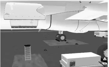
Figure 4. Open the door of afterward cargo compartment.
Figure 5. D&A about temperature sensor.
Through the fault information on the MCDU, locate the fault point, consult the manual TSM, then troubleshooting operation. Part of the simulation is as follows: figures 4-5. After D&A, carry out restoration work, reset circuit breakers 30HN and 30HN. Re-test the air condition system on the MCDU, the page is displayed normal. Indicates the fault has been excluded.
CONCLUSION
This paper discusses the D&A process modeling in maintenance training system. And use Multi-signal flow diagram to set up the simulation model, which use matrix relations of tool flow, components relationship flow. In the end the model has applied
OPEN 826
door Platform Remove panel
APU BLEED
(off & notice) )
ENG 1&2 BLEED
(off & notice) )
C/B
30HN open ¬ice
C/B
31HNopen ¬ice
3 P 2 P
1 P
5 P 4
P
O-rings Sensor Wire Caps
CONNECTOR
5 P
6 P
7 P
[image:5.612.203.393.419.541.2]to OSG-based 3D virtual maintenance equipment platforms. It provides a method for simulate the D&A process of the component , and simulate the whole process about trouble shooting by simulating the signal transmission among maintenance computer, fault component, and multifunction display assembly.
ACKNOWLEDGEMENTS
Corresponding author: Ke Liang, 825987996@ qq.com, Civil Aviation Flight University of China, GuangHan 618307, China
REFERENCES
1. Liu Hui, Hao Jianping. Design and Implementation of Virtual Maintenance Simulation Based Maintainability Analysis System [J]. Journal of System Simulation,, 2006, 18(2) : 378-394
2. Zhou Dong, Lv Chuan. Modeling and control implementation of virtual maintenance simulation [J]. Journal of Beijing University of Aeronautics and Astronautics, 2006, 32(7): 843-846
3. Liu Jiaxue, Kang Xuan, Geng Hong. Maintenance Test Process Simulation Based on Multi-signal Flow Graphs Model [J]. Computer Application and Software, 2014, 31(3): 39-42
4. Chen Jingjie, Li Huiru. Hierarchical analysis and UML state machine in Disassembly and assembly process simulation [J] Journal of Graphics2014, 35(6): 481-483
5. Ou Aihui. An Modeling and Analysis Method of Testability for Radar System Based on Multi-Signal Flow Graphs [J]. Ordnance Industry Automation, 2014, 33(4): 56-58.
6. Han Yujie. Modeling and Analysis Method Based on Multi-Signal Flow Graph using Multi- Functional Fault Model [J]. Journal of Computer Research and Development, 2010, 47: 96-100 7. Zhang Zhonghua, Geng Hong. Hierarchical analysis and UML state machine in Disassembly and
assembly process simulation [J]. Journal of Civil Aviation University of China, 2015, 32(3): 32-35. 8. Yu Pengfei, Shi Heping, Rui Kehui. Research on the Method of Virtual Maintenance Action
Simulation Based on Action Object [J]. Journal of the Academy of Equipment Command & Technology, 2009, 20(5): 126-129[chinese]