3270 Information Display System
-- -- -- --
- -
- - -
--
-
----
-
-
---,-
3174 Subsystem Control Unit
Models 1 L, 1 R, 2R, and 3R
User's Guide
Introduction
Operation
Problem Determination
Status Codes
Setup and Relocation
GA23-0337 -1
The following warning statements (required by country regulatory agencies) are applicable in the countries indicated.
United States
Warning: This equipment generates, uses, and can radiate radio frequency energy and if not installed and used in accordance with the instructions manual, may cause interference to radio communications. It has been tested and found to comply with the limits for a Class A computing device pursuant to Subpart J of Part 15 of FCC Rules, which are designed to provide reasonable protection against such interference when operated in a commercial environment. Operation of this equipment in a residential area is likely to cause interference in which case the user at his own expense will be required to take whatever measures may be required to correct the interference.
Additional
mM
StatementThis warning is also applicable to all attaching units produced for use in the U.S.A. that have been manu-factured after December 31, 1980. A notice of compliance has been affixed within the customer access area of all affected units.
United Kingdom
Warning: This
mM
product is made to high Safety standards. It complies inherently with Telecommuni-cations safety standard BS6301. It is not designed to provide protection from excessive voltages appearing externally at its interfaces. Therefore, when this product is connected to a public telecommunications network via any other equipment, and you connect to this product items not supplied bymM
United Kingdom Ltd., you must comply with mandatory telecommunications safety requirements.You may do this either by choosing products which also are approved as complying to BS6301 or British Telecom Technical Guide No. 26, or by the use of approved safety barriers. Consult the local office of your public telecommunications operator, for advice and permission to make the connections.
Second Edition (December 1987)
This major revision obsoletes and replaces GA23-0337-0.
Changes are made periodically to the information herein; before using this publication in connection with the operation ofIBM systems, consult the latest IBM System/370, 30xx, and 4300 Processors Bibliography, GC20-0001, for the editions that are applicable and current.
References in this publication to IBM products, programs, or services do not imply that IBM intends to make these available in all countries in which IBM operates. Any reference to an IBM licensed program in this publication is not intended to state or imply that only IBM's licensed program may be used. Any func-tionally equivalent program may be used instead.
Publications are not stocked at the address given below. Requests for IBM publications should be made to your IBM representative or to the IBM branch office serving your locality.
A form for users' comments is provided at the back of this publication. If the form is missing, address com-ments to IBM Corporation, Department B02, P.O. Box 12195, Research Triangle Park, N.C., U.S.A. 27709-9990. IBM may use or distribute whatever information you supply in any way it believes appropriate without incurring any obligation to you.
Contents
Chapter 1. Introduction 1-1
3174 Subsystem Control Unit Models 1-2 3174 Description 1-4
3174 Model Descriptions 1-4 3174 Models and Features 1-4
This User's Guide and the 3174 Library 1-6 The Purpose of This User's Guide 1-7
Control Unit Setup and Relocation 1-7 Operations with Diskettes 1-9
Status Codes 1-9
Online and Offline Tests 1-11 Problem Solving 1-11
Chapter 2. Operation 2-1
3174 Panels, Switches, and Indicators 2-2 Power Panel and Power Supply 2-4 Operator Panel 2-6
3174 Ports and Cables 2-8
3270 Terminal Port Addresses 2-12
For Terminals Directly Connected to the Terminal Adapter For Terminals Indirectly Connected to the Terminal Adapter Diskettes and Diskette Drives 2-13
Description of 3174 Diskettes 2-13 How to Handle Diskettes 2-14
How to Insert and Remove Diskettes 2-15 Inserting Diskettes 2-15
Removing Diskettes 2-16
Diskette Shipping and Receiving 2-16 Long-Term Storage of Diskettes 2-16 Making the 3174 Operational 2-17
For ModellL 2-17
How to IML When Power Is Off 2-17 How to IML When Power Is On 2-19 For Models lR, 2R, and 3R 2-20 Taking the 3174 Offline 2-21
For ModellL 2-21
For Models 1R, 2R, and 3R 2-21 Displaying the Master Menu 2-22
Replacing the Encrypt/Decrypt Adapter Battery 2-24
Chapter 3. Control Unit Problem Determination 3-1 Initial Symptom/Action Table 3-3
Symptom/Decision Chart 3-4 Checking Control Unit Power 3-7
For ModellL 3-7
For Models 1R, 2R, and 3R 3-8 Checking AC Power 3-9
2-12 2-12
Check Cond Indicator Lit and No Status Code 3-10 Forcing the Control Unit Offline 3-11
3270 Tenninal Connection Problems 3-13
Collecting Infonnation about the Problem 3-13
1 - Identify the Failing Terminal and Its Control Unit 3-16 2 - Obtain Physical-Connection Information 3-16
3-Determine How the Terminal Is Connected to the 3174 3-16 4 - Detennine the Status of Other Connected Tenninals 3-16 Selecting a 3270 Terminal Symptom 3-18
Procedure A - All Tenninals Are Failing 3-19
Procedure B - All Tenninals Connected to a TMA Are Failing 3-21 Procedure C - All Terminals Connected to a 3299 Are Failing 3-23 Procedure D - One Tenninal Connected to a TMA Is Failing 3-29 Procedure E - One Tenninal Connected to a 3299 Is Failing 3-34 Procedure F - A Directly Connected Tenninal Is Failing 3-38 Procedure G - A Remote Host Connection Is Failing 3-43 3299 Service/Replacement Procedure 3-48
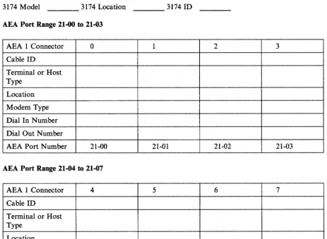
ASCII Terminal Connection Problems 3-49 Collecting Information about the Problem 3-49
Asynchronous Emulation Adapter 1 Port Range 21-00 to 21-07 3-50 1 - Identify the Failing Tenninal and Its Control Unit 3-52 2 - Obtain Physical-Connection Infonnation 3-52
3 - Determine How the Terminal Is Connected to the 3174 3-52 4 - Detennine the Status of Other Connected Tenninals 3-55 Selecting an ASCII Tenninal Symptom 3-56
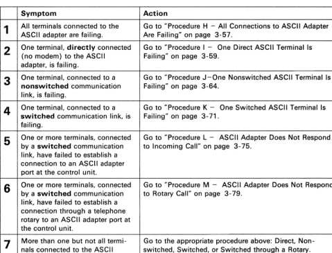
Procedure H - All Connections to ASCII Adapter Are Failing 3-57 Procedure I - One Direct ASCII Terminal Is Failing 3-59
Procedure J - One Nonswitched ASCII Terminal Is Failing 3-64 Procedure K - One Switched ASCII Tenninal Is Failing 3-71 Procedure L - ASCII Adapter Does Not Respond to Incoming Call Procedure M - ASCII Adapter Does Not Respond to Rotary Call ASCII Host Connection Problems 3-83
Collecting Infonnation about the Problem 3-83
Asynchronous Emulation Adapter 1 Port Range 21-00 to 21-07 3-84 1 - Identify the Failing Host and Its Control Unit 3-86
2 - Obtain Physical-Connection Information 3-86
3 - Detennine How the Host Is Connected to the 3174 3-86 4 - Determine the Status of Other Connected Hosts 3-89 Selecting an ASCII Host System Symptom 3-90
Procedure N - All Host Connections to ASCII Adapter Are Failing Procedure 0 - One Direct ASCII Host Is Failing 3-93
Procedure P - One Nonswitched ASCII Host Is Failing 3-97 Procedure Q - One Switched ASCII Host Is Failing 3-102 Offline Tests 3-108
Test Operations 3-108 Alt 2 IML Tests 3-108 Alt 1 IML Tests 3-110
Communication Adapter and Communication Cable Test 3-110 Token-Ring Adapter and Cable Test 3-114
Chapter 4. Status Codes 4-1 Description 4-2
How to Display Status Codes 4-2 Status Code Chart 4-4
iv
3-75 3-79
Chapter 5. Customer Setup and Relocation Instructions 5-1 Model 1L Setup and Relocation Instructions 5-2
How to Set Up the 3174 Model1L 5-3 How to Relocate the 3174 ModellL 5-8
Models 1R, 2R, and 3R Setup and Relocation Instructions 5-12 How to Set Up the 3174 Models 1R, 2R, and 3R 5-13 How to Relocate the 3174 Models 1 R, 2R, and 3R 5-20
Appendix A. Online Tests A-I Online Test Summary A-2
Entering and Exiting Test Mode A-2 Displaying the Test Menu A-3 Terminal Check - Test 0 A-4 Display Logs Menu - Test 1 A-5 Configuration Menu - Test 2 A-7 Display Status Summary - Test 3 A-9 Reset Log - Test 4 A-12
Vital Data - Test 5 A-13 Display Storage - Test 6 A-I4 Color Convergence - Test 7 A-14
Extended Function and Program Symbols - Test 8 A-14 Token-Ring Test - Test 9 A-15
Definition of Token-Ring Status Codes A-16 Definition of Token-Ring Adapter Fields A-17 Definition of Link Fields A-18
Online Port Test - Test 10 A-20
How to Run the Terminal Adapter Port Test How to Run the TMA/3299 Model 2 Port Test Test 12: Asynchronous Emulation Adapter Tests
Appendix B. Cables and Connections B-1 3174 Connection Overview B-2
3174 Adapter Hardware Group Numbers B-2 Terminal Adapter (HG= 26) B-2
ASCII Adapter (HG=21, 22, or 23) B-2 Token-Ring Adapter (HG=31) B-2 Establishing Communication B-3
Configurations B-5
A-20 A-21 A-22
Asynchronous Emulation Adapter Feature B-8
Asynchronous Emulation Adapter Communication B-9 Asynchronous Emulation Adapter (AEA) Hardware B-ll Communication Links and Associated Hardware B-13 Physical and Logical Paths B-14
Logical Path B-15 Connection Menu B-16 Customizing B-18
Stations and Sets B-I8 Port Type and Port Sets B-19
How to Disconnect and Connect Cables B-21 Terminal Cable Connectors B-2l
Modular Telephone Plug Connectors B-22 Terminal Adapter Connectors B-22 BNC and DPC Connectors B-23 3174 Cables, Plugs, and Accessories B-24
List of Abbreviations
X-I
Glossary
X-9
Index . X-27
Figures
1-1.
3174 Subsystem Control Unit Models IL, IR, 2R, and 3R
1-2
1-2.
3174 Subsystem Control Unit Models 51R, 52R, and 53R
1-3
1-3.
3174 Subsystem Control Unit Models SIR and S2R
1-3
1-4.
3174 Subsystem Control Unit Features
1-5
I-S.
Locations of &itcapl. and &itcap2.
1-6
efke.
1-6.
Packing the Control Unit for Relocation
I-S
2-1.
3174 Control Unit Models IL, IR, 2R, and 3R - Front View
2-2
2-2.
3174 Control Unit Models IL, lR, 2R, and 3R - Rear View
2-3
2-3.
3174 Power Panel
2-4
2-4.
Sequence and Control Cable and Connector
2-S 2-S.3174 Operator Panel
2-6
2-6.
Sample Cabling Layout for Models lR and 2R
2-S
2-7.
Sample Cabling Layout for Model 3R
2-9
2-8.
Sample Cabling Layout for Model IL
2-10
2-9.
Sample ASCII Connection Diagram
2-11
3-1.
Initial Symptom/Action Table
3-3
3-2.
Symptom/Decision Chart
3-4
3-3.
Sample Overview Cable Connection Worksheet
3-14
3-4.
Sample 3299 Cable Connection Worksheet
3-1S3-S.
Sample Physical Connection Diagram (3270 Terminals)
3-17
3-6.
3270 Terminal Connection Problems
3-18
3-7.
Sample Cabling Worksheet (ASCII Terminals)
3-50
3-8.
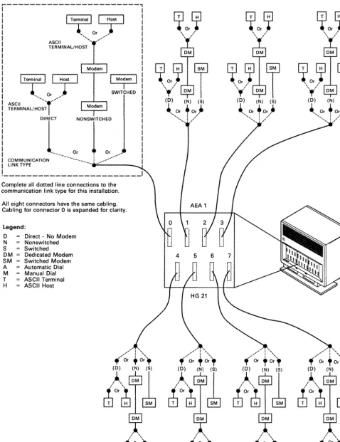
Sample Physical Connection Diagram (ASCII Terminals)
3-S33-9.
ASCII Terminal Connection Problems
3-S63-10.
Sample Cabling Worksheet (ASCII Host System)
3-S4
3-11.
Sample Physical Connection Diagram (ASCII Host System)
3-S7
3-12.
ASCII Host Connection Problems
3-90
3-13.
Communication Cable Switch Settings
3-111
A-I.
3174 Test Menu
A-3
A-2.
Test 0 Display Pattern
A-4
A-3.
Test 1 Menu
A-SA-4.
RTM Log for Test 1, Option 1
A-SA-S.
Log Record Display Panel for Test I, Options 2 through 6
A-6
A-6.
Test 2 Menu
A-7
A-7.
Hardware Configuration Table for Test 2, Option I
A-S
A-S.
Test 3 Menu
A-9
A-9.
Test 4 Menu
A-12
A-IO.
Test
SMenu
A-13
A-II.
Token-Ring Test Menu
A-15
A-12.
Token-Ring Status Test Panel
A-16
A-13.
Token-Ring Adapter Status Summary Panel
A-17
A-14.
Link Status Summary Panel
A-IS
A-IS.
Gateway Host Status Summary for Test 9, Option S
A-19
A-I6.
Test 10 - Port Wrap Test Menu
A-20
A-17.
Test 12 Menu
A-22
A-IS.
Asynchronous Emulation Adapter Port Tests Menu
A-23
A-19.
WXYYZZ Override Settings
A-25
A-20.
Test 12 Status Summary Panel
A-25
B-1.
3270 Communication
B-S
B-2.
ASCII Communication
B-S
B-3.
3270 Terminal Communicating with an ASCII Host
B-9
B-4. B-5. B-6. B-7.
B-8.
B-9.
B-lO.
B-ll. B-12. B-13. B-14. B-15. B-16. B-17.
B-18.
viii
ASCII Terminal Communicating with an IBM Host ASCII Terminal Communicating with an ASCII Host Asynchronous Emulation Adapter Hardware B-ll AEA I/O Panel B-12
Communication Equipment B-13 Physical and Logical Paths B-14 Printer Logical Path B-15 Display Logical Path B-15 Connection Menu B-16 Connection Menu Option 1 Connection Menu Option 2 Host Set and Terminal Set Port Sets B-19
B-I6 B-I7
B-I8
Connected Terminal and Port Sets B-20 BNC and DPC connectors B-23
B-9
Preface
This manual contains operator reference information and problem determination procedures for the IBM 3174 Subsystem Control Unit Models 51R, 52R, and 53R.
Who This Book Is For
This book is written for anyone assigned to operate, and handle problems with, the 3174 Subsystem Control Unit Models 51R, 52R, and 53R. This book should remain with the control unit so that the responsible people can refer to it when doing operating or problem determination procedures.
How This Book Is Organized
This manual has five chapters and two appendixes:
• Chapter 1 contains an introduction to the 3174 Subsystem Control Unit Models 51 R, 52R, and 53R.
• Chapter 2 describes the location and function of the switches, indicators, ports, and cables on the 3174 Subsystem Control Unit Models 5IR, 52R, and 53R. Chapter 2 also contains basic operating
procedures, such as turning on power, loading microcode, and displaying system menus.
• Chapter 3 contains a symptom/action table, problem determination procedures, and terminal and cabling error-isolation procedures.
• Chapter 4 contains the status codes.
• Chapter 5 contain setup and relocation procedures.
• Appendix A contains reference information about online tests.
• Appendix B contains reference information about cable connectors.
Sometimes, the procedures ask you to do problem determination on one of the terminals attached to the 3174. Be sure you have a copy of the problem determination guide for each terminal type attached to your 3174.
Related Publications
IBM 3270 Information Display System:
x
3174 Subsystem Control Unit; Site Planning, GA23-0213
3174 Subsystem Control Unit; Customizing Guide, GA23-0214
3174 Subsystem Control Unit; Customer Extended Problem Determination, GA23-0217
3174 Subsystem Control Unit; Terminal User's Reference for Expanded Functions, GA23-0333
3174 Subsystem Control Unit; Functional Description, GA23-0218
3174 Subsystem Control Unit Models 5IR, 52R, and 53R; User's Guide, GA23-0333
3174 Publications
At the central site
To do site physical planning
3174 Site Planning
GA23-0213
To manage problems
3174 Customer Extended Problem Determination GA23-0217 3270 Physical Planning Template GX27-2999 3174 User's Guide
GA23-0337 (for Models 1 L, 1 R, 2R, and 3R) GA23-0333 (for Models 51 R, 52R, and 53R) GA23-0313 (for Models 81 Rand 82R)
To plan for and use the Asynchronous Emulation Adapter feature
3174 Asynchronous Emulation Adapter Introduction GA23-0331
For terminal users
3174 Terminal User's Reference for Expanded Functions GA23-0332 3174 Terminal User's Reference for Expanded Functions
GA23-0332
• In addition, host configuration and network planning and diagnosis publications contain relevant 3174 information.
• A copy of the publications that come with each control unit should also be available at the central site (see next page).
(Part 1 of 2)
To plan and do microcode customizing
3174 Customizing Guide
GA23-0214
3174 Central Site Customizing User's Guide
GA23-0342
To understand or write data stream code or to diagnose data stream problems
3174 Functional Description
GA23·0218
3174 Publications
With each control unit
To set up, relocate, and operate the control unit and to handle problems
3174 User's Guide
3174 Maintenance Information
(Part 2 of 2)
GA23-0337 (for Models 1 L, 1 R, 2R, and 3R) GA23-0333 (for Models 51 R, 52R, and 53R) GA23-0313 (for Models 81 Rand 82R)
For IBM service representative A yellow card stored in the diskette storage pocket of
the control unit may help you locate this publication.
SY27-2572 (for Models 1 L, 1 R, 2R, and 3R) SY27-2573 (for Models 51 R, 52R, and 53R) SY27-2584 (for Models 81 Rand 82R)
With features
• 3174 Encrypt/Decrypt Adapter: Customer Setup Instructions, GA23-0262 • 3174 1.2MB Diskette Drive: Customer Setup Instructions, GA23-0263 • 3174 Terminal MUltiplexer Adapter: Customer Setup Instructions, GA23-0265
• 3174 Model/Communications Interface Conversion: Customer Setup Instructions, GA23-0295 • 3174 IBM Token-Ring Network 3270 Gateway: Customer Setup Instructions, GA23-0329 • 3174 Storage Expansion Feature: Customer Setup Instructions, GA23-0330
• 3174 Asynchronous Emulation Adapter: Customer Setup Instructions, GA23-0341
Additional 3270 related publications
See the 3270 Library User's Guide, GA23-0058
At the central site (optional)
xii
3270 Binder
SX23-0331
Package of inserts for tailoring 3270 binders SX23-0332
At customer option, binders and inserts can be ordered to assemble: • 3270 planning volumes
Summary of Changes
Summary of Changes
Second Edition (December 1987)
New information has been added primarily for the Asynchronous Emulation Adapter feature of the 3174 Subsystem Control Unit, Configuration A, Release 3:
• Procedures H through Q in Chapter 3
• New Status Codes in Chapter 4
• ASCII Test 12 in Appendix A
• ASCII tutorials and connectors in Appendix B.
Introduction
3174 Subsystem Control Unit Models
The 3174 is available in nine models:
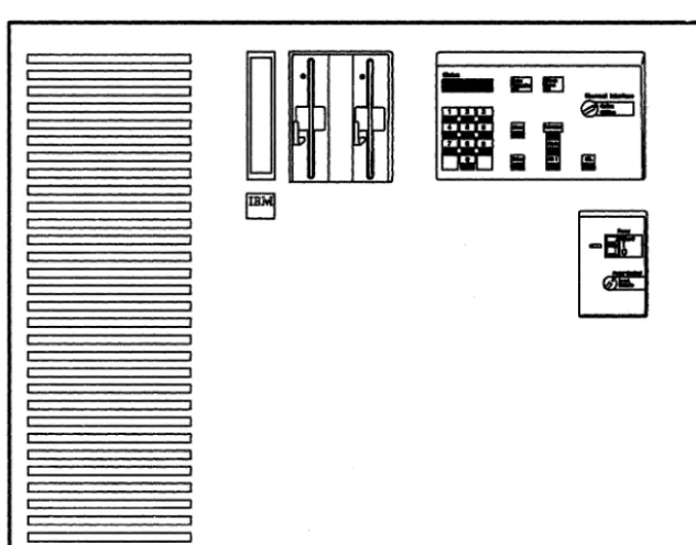
3174 Models lL, lR, 2R, and 3R (see Figure 1-1)
3174 Models 51R, 52R, and 53R (see Figure 1-2 on page 1-3) 3174 Models 81R and 82R (see Figure 1-3 on page 1-3).
The L in the model number indicates that the control unit is attached locally to the host computer by a channel. The R in the model number indicates that the control unit is attached remotely to the host com-puter by a telecommunications link.
Figure 1-1. 3174 Subsystem Control Unit Models lL, lR, 2R, and 3R
[image:17.630.53.369.241.488.2]Introduction
~ ~
rrrrrrrrrrrrrr
11111111111111111111111111111111111111
~ ~
rrrrrrrrrrrrrr
~ ~
rrrrrrrrrrrrrr
. sg ,
~
I
-ll~~1
' - - - -_ _ - - - - ' DODoc::::c:::J
Figure 1-2.3174 Subsystem Control Unit Models SIR, S2R, and S3R
Ir
II
("'J
I
I CJV
\J
Status . . . .
II
II
aa Ch.ck . . .~~' I~I ~ ~~
o
Ent.rI I I I I I I
Figure 1-3. 3174 Subsystem Control Unit Models 81 Rand 82R
[image:18.629.87.565.107.344.2]Introduction
3174 Description
The 3174 links 3270 display stations and printers (from now on, display stations and printers will be referred to as terminals) to a central computer (host). The 3270 terminals attach to the control unit directly through the terminal adapter or indirectly through an internal Terminal Multiplexer Adapter (TMA), or through an external terminal multiplexer (for example, a 3299 Terminal Multiplexer).
Some models of the 3174 allow attachment of ASCII hosts, terminals, or printers through an optional feature called the Asynchronous Emulation Adapter.
One 5-1/4 inch, high-capacity, 1.2-megabyte (Mb) diskette drive is standard for all models. A second diskette drive must be installed if distributed function terminals (such as a 3290 Information Panel) are to be used for downstream load, or if an Asynchronous Emulation Adapter is installed.
Note: The second diskette drive is not available on models 81R and 82R.
3174 Model Descriptions
The 3174 Models lL, IR, 2R, and 3R have an integrated four-port Terminal Adapter for attaching category A terminals either directly or by one to four Terminal Multiplexer Adapters (TMAs), or with a combination of external terminal multiplexers. These models support a maximum of 32 terminals.
The 3174 Models 51R, 52R, and 53R have an integrated nine-port Terminal Adapter for attaching category A terminals directly or indirectly through external terminal multiplexers. These models support a maximum of 16 terminals.
The 3174 Models SIR and 82R have an integrated four-port Terminal Adapter for attaching category A ter-minals directly or indirectly through one external terminal multiplexer. These models support a maximum of 8 terminals.
ModellL The Model 1L has an S/370-type channel adapter for Systems Network Architec-ture (SNA) and non-SNA for local attachment.
Models IR, 51R, and 8lR The Models IR, 5IR, and 8IR are designed for remote operation. They contain EIA RS-232C/CCITT V.24 and CCITT V.35 interfaces for SNA/SDLC, BSC, or X.25 remote link attachment of IBM host.
Models 2R, 52R, and 82R The Models 2R, 52R, and 82R are designed for remote operation. They contain an X.2I interface (CCITT V.ll) for SNA/SDLC or X.25 remote link attachment of IBM host.
Models 3R and 53R The Models 3R and 53R are designed for remote connection to a Token-Ring Network. They contain a Token-Ring Adapter and cable for connection to a Token-Ring Network.
3174 Models and Features
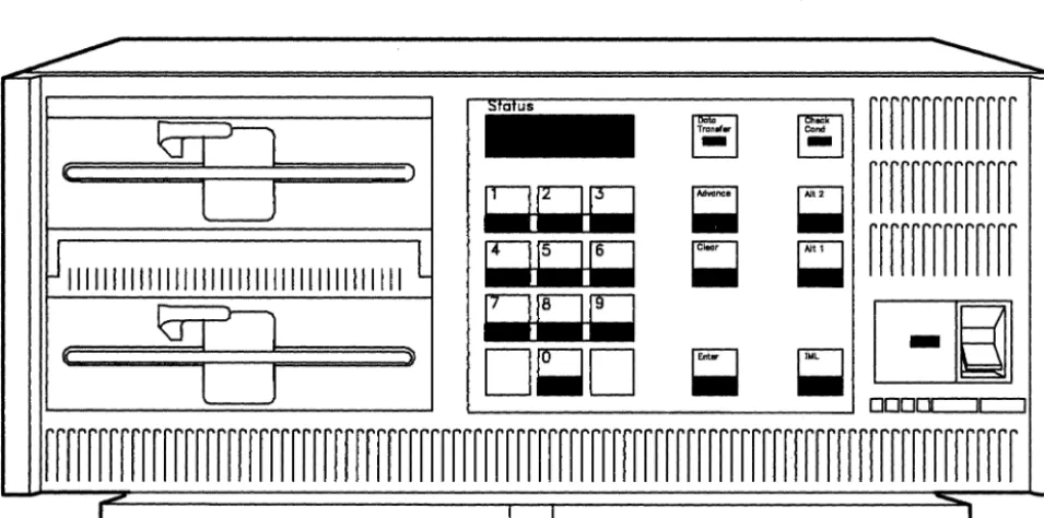
See Figure 1-4 on page 1-5 for additional 3174 subsystem features.
Introduction
3174
Feature
Models
Functions
1 L, 1 R, Attaches four 3270 display stations and printers directly or 2R,3R up to thirty-two 3270 display stations and printers through
four terminal multiplexer adapters, or four terminal multiplexers, such as a 3299.
51 R, 52R, Attaches nine 3270 display stations and printers directly or 53R up to sixteen display stations using one or two terminal
multiplexers, such as a 3299.
81 R, 82R Attaches four 3270 display stations and printers directly or eight 3270 display stations or printers through a terminal multiplexer, such as a 3299.
Terminal Multiplexer 1 L, 1 R, Attaches eight 3270 Display stations and printers. The Adapter (TMA) 2R, 3R TMA connects to the terminal adapter with coaxial cable.
Up to four TMAs can be installed.
Type 1 Communication 1 L, 1 R, Provides a telecommunication path to a host. Adapter (EIA/V.35) 3R,51R
Type 2 Communication 1 L, 2R, Provides a telecommunication path to a host. Adapter (X.21) 3R,52R
Token-Ring Network 1 L, 1 R, Connects an IBM Token-Ring to the 3174 and serves as the 3270 Gateway 2R, 51 R, gateway controller for the Token-Ring to the host. This
52R feature includes a Token-Ring Adapter and S level micro-code.
Token- Ring Adapter 3R,53R Connects the 3174 to an IBM Token-Ring Network.
Asynchronous Emu- 1 L, 1 R, Provides attachment of eight ASCII display stations, lation Adapter 2R,3R, printers, or hosts. The display station, printer, or host is
51 R, 52R attached directly, or through a nonswitched modem, or through a switched modem. Three AEAs, are the maximum for Models 1 L, 1 R, and 2R; one AEA for Models 51 Rand 52R.
The AEA allows ASCII devices to communicate with ASCII hosts, ASCII devices to emulate 3270 devices to communi-cate with 3270/IBM hosts, and 3270 terminals attached to the 3174 to emulate ASCII display stations Or printers to communicate with ASCII hosts.
Second Diskette Drive 1 L, 1 R, Is normally used for Downstream Load diskettes when dis-2R, 3R, tributed function terminals are attached to the control unit. 51 R, 52R, Is also required if an Asynchronous Emulation Adapter is 53R installed in the control unit.
Encrypt/ Decrypt 1 R, 2R, 3R Allows encryption of data sent to and from the host. Adapter
Storage Expansion 1 L, 1 R, Allows expansion to a maximum of 3 megabytes. 2R,3R
51R,52R Allows expansion to a maximum of 1 megabyte.
Figure 1-4. 3174 Subsystem Control Unit Features
[image:20.629.82.570.56.698.2]Introduction
This User's Guide and the 3174 Library
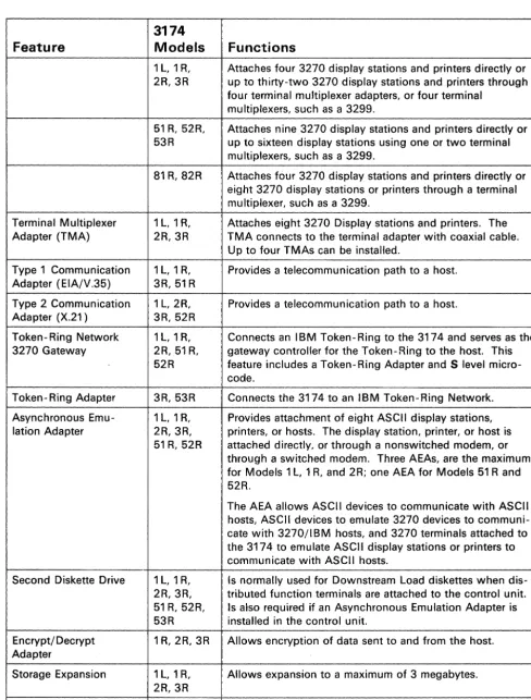
The User's Guide is complemented by other documents in the 3174 library:
• The 3174 Customer Extended Problem Determination is used by skilled customer personnel at the host site (see Figure 1-5) to help the User's Guide audience at the remote site.
• The 3174 Customizing Guide is used by skilled customer personnel to complete customization worksheet information.
• The 3174 Models 1L, 1R, 2R, and 3R Maintenance Information manual (MIM), used by the
IBM
service representative, is another level of skilled support for the remote user of this User's Guide.3174 Control Unit
Figure 1-5. Locations of 3174 Extended Problem Determination and User's Guide
[image:21.629.48.517.130.464.2]Introduction
The Purpose of This User's Guide
This guide is intended for use by an operator at a remote site (see Figure 1-5 on page 1-6). This user is expected to contact a help desk when an unusual problem or event occurs.
This guide may be different from other system documents you may be familiar with in that it consolidates within one document the information you will need for several tasks. The remote site user, for whom this book is intended, will use it for:
• Setting up or relocating this control unit (Chapter 5)
• Identifying the correct cables and connectors (Appendix B)
• Using diskettes when operating the control unit (Chapter 2)
• Interpreting the meaning of status codes (Chapter 4)
• Running offline and online tests (Chapter 3 and Appendix A)
• Helping to solve problems with the control units, terminal multiplexers, terminals, or the cables con-necting control unit, multiplexers, and terminals (Chapter 3).
Control Unit Setup and Relocation
You will need to know how to prepare the 3174 Subsystem Control Unit for operation after it is unpacked. Figure 1-6 on page 1-8 is an example of how to repack a control unit for relocation. The step-by-step proce-dures in Chapter 5 will direct you to set up or relocate this control unit and to use the Utility diskette to complete the installation of the control unit.
Introduction
•
•
...
h Ir-h
to I-'
~
I-'Figure 1-6. Packing the Control Unit for Relocation
[image:23.626.56.512.59.570.2]Introduction
Operations with Diskettes
A common problem among all users is inserting the wrong diskette for a particular operation. It does not take long to learn how to handle and care for your diskettes, but it does take concentration at all times to use the correct diskette and avert the obvious problems.
INSERT
o o
CORRECT
DISKETTE?
Directions for operating the 3174 Subsystem Control Unit are presented in Chapter 2 along with a description of each switch, connector, and indicator.
Status Codes
Your success with the 3174 Models 1L, 1R, 2R, and 3R is enhanced by the ease with which you can look up status codes in Chapter 4 and perform the actions. From the time you turn it on, the control unit will be communicating with status codes (see the following diagram): prompting you for responses, informing you about the progress of an operation, or indicating a problem that exists. Your ability to respond will depend on how familiar you are with the status code actions in Chapter 4.
Introduction
1-10
C de? (Refer to Status 0 .
~~
-@=
I
;;}
I
iii
~
Introduction
Online and Offline Tests
As with diskettes, it will not take you long to learn how to run online tests (see Appendix A, "Online Tests" on page A-I) and offline tests (see "Offline Tests" on page 3-108). When you are working with others (while solving a problem, for instance), knowing the results of pertinent tests will enable you to help your support groups, who, in turn, will help you solve a problem.
Online and offline tests, then, are important tools to help you become more effective at your work.
Problem Solving
Because your equipment is functioning with a variety of programs and other equipment, solving problems must be a team effort. And you play the most important role.
The 3174 Subsystem Control Unit and the attached terminals are usually part of a larger network, and a problem cannot be solved unless it is quickly isolated. The problem determination procedures in Chapter 3 will enable you to isolate problems quickly and effectively.
3299
Working Terminal
For example, many problems are the result of poor connections; so you will follow a step-by-step procedure (see "Initial Symptom/Action Table" on page 3-3) that may ask you to exchange cables or terminals to find the source of the problem.
You will be doing your part of your team's problem-solving effort when you have gathered all the informa-tion available to you before you call for assistance about a problem.
Chapter 2. Operation
3174 Panels, Switches, and Indicators 2-2 Power Panel and Power Supply 2-4 Operator Panel 2-6
3174 Ports and Cables 2-8
3270 Terminal Port Addresses 2-12
For Terminals Directly Connected to the Terminal Adapter For Terminals Indirectly Connected to the Terminal Adapter Diskettes and Diskette Drives 2-13
Description of 3174 Diskettes 2-13 How to Handle Diskettes 2-14
How to Insert and Remove Diskettes 2-15 Inserting Diskettes 2-15
Removing Diskettes 2-16
Diskette Shipping and Receiving 2-16 Long-Term Storage of Diskettes 2-16 Making the 3174 Operational 2-17
ForModel1L 2-17
How to IML When Power Is Off 2-17 How to IML When Power Is On 2-19 For Models 1 R, 2R, and 3R 2-20 Taking the 3174 Offline 2-21
For Model lL 2-21
For Models lR, 2R, and 3R 2-21 Displaying the Master Menu 2-22
Replacing the Encrypt/Decrypt Adapter Battery 2-24
2-12
2-12
Operation
3174 Panels, Switches, and Indicators
3174 Panels, Switches, and Indicators
The front panel on the IBM 3174 Subsystem Control Unit contains a power panel, an operator panel, a diskette drive(s), and a diskette storage pocket. Figure 2-1 shows a front view of the 3174 control unit. Notice that only Model IL has a Channel Interface switch and a Power Control switch. Figure 2-2 shows a rear view of the control unit.
Front Door Latch Release Pushbutton
Diskette Storage Pocket
Diskette Drive 1 Diskette Drive 2
(optional) , . . - - - Operator Panel
rr=;c.=====~---t-
Statusf- Display
iiii!I.
IE3 I!I.:1
@iEj
Channel Interface ... \ t - - - l l - Switch(Model 1 L only)
F=7'f)-,
Power Switch)--+- Power Panel Power Control
'---+- Switch
(Model 1 L only) Model Number
Figure 2-1. 3174 Control Unit Models IL, IR, 2R, and 3R - Front View
ASCII Adapter Connector Panels
/ '\
D
/
\
/
I
O© 1 2 3© O© 1 2 3© O© 1 2 3©
I I I I
I I I I I I I I
4 5 6 7 4 5 6 7 4 5 6 7
I I I I
I I I I
I I I I
21 22 23
~ c::::J
-
c::::J /I ~I I / '
~
Hardware Group (HG) Numbers
I
I
3174 Panels, Switches, and Indicators
'\
Figure 2-2. 3174 Control Unit Models 1L, 1R, 2R, and 3R ~ Rear View
Power Panel
Power Panel and Power Supply
Figure 2-3 shows the power panel for the 3174 control unit.
DC Power Indicator
Model 1 L
Power Control • Local
Remote I
Figure 2-3. 3174 Power Panel
Model 1 R/2R/3R
I
The functions of the power indicators and switches are as follows. Indicator
or Switch
DC Power
AC Power
Power
2-4
Description
This green indicator is lit when the control unit is on. It shows that the dc power supply voltages are at the correct levels.
This green indicator is located on the power supply (see Figure 2-4 on page 2-5) and indicates that ac power is supplied to the control unit.
For Models lR, 2R, and 3R:
You turn on the Model 1 R, 2R, and 3R control units by lifting the Power switch to I. An initial microcode load (lML) sequence starts when you turn on the control unit. You turn off the control unit by pressing the Power switch to O. To turn the control unit on and off, refer to "Making the 3174 Operational" on page 2-17 and "Taking the 3174 Offline" on page 2-21.
For Model lL:
Indicator or Switch
Power Control
Description
Model lL only:
Power Panel
When this switch is in the Local position, power to the 3174 is controlled by the Power switch.
When this switch is in the Remote position, power to the control unit is controlled by a power sequence from the host computer. Remote power control requires a Sequence and Control cable that is plugged into the control unit power supply (see Figure 2-4). Note: To use remote power control, the Power switch must be in the I (on) position. Warning: If your control unit does not have a Sequence and Control cable, do not tum the Power Control switch to Remote. To do so would tum off the 3174 .
..,.".. .... _ - - - . AC Power Indicator Control Unit
Power Supply
11 12 13 14 1 5 16 17 18 19 20 21 22 23 2
Figure 2-4. Sequence and Control Cable and Connector
Sequence and Control Cable
Operator Panel
Operator Panel
The operator panel for the 3174 control unit is shown in Figure 2-5.
Siolus
~ ~
eondChonnel Inlerface
Model 1 L
0=·
onlyOperator keypad
~
~
~
D~D
;;
~
~
Figure 2-5. 3174 Operator Panel
The functions of the indicators and controls on the operator panel are as follows.
Indicator or Control
Status
Check Cond
Data Transfer
Offline
IML
2-6
Description
These four indicators display numeric status codes or keypad input.
This indicator is lit when the control unit has a major hardware or microcode failure.
This indicator is lit or blinking when the control unit is transmitting data to the host or receiving data from the host.
Model 1L only:
This indicator is lit after the Channel Interface switch is turned to Offline, and indi-cates that the control unit is logically disconnected from the host.
When this key is pressed, all indicators on the operator panel are lit and 8888 is displayed in the Status indicators. When the key is released, IML tests run and, if no errors are found, operational microcode is loaded into control unit storage from a customized Control diskette in drive 1 or 2. A normal IML is completed when 501 appears in the Status display. A 3174 appears in the Status display when the host system brings the control unit online. If a failure occurs during any portion of the IML sequence, a status code appears in the Status display.
Indicator or Control
Alt 1
Alt 2
Enter
Clear
Keypad
Advance
Channel Interface
Operator Panel
Description
Alt 1 is pressed in conjunction with either IML or a power-on sequence to do any of the following:
• Customer Setup tests (see the Setup and Relocation Instructions for your control unit model)
• Customizing procedures • Specific tests.
The Utility diskette contains offline testing and customizing microcode.
An Alt 1 IML (see "Alt 1 IML Tests" on page 3-110) causes a 40 prompt to appear in the Status display. You then either press Enter to display a menu of procedures (Master Menu) at the terminal connected to port 0, or make a keypad entry and press Enter to request one of the specified functions.
Alt 2 (see "Alt 2 IML Tests" on page 3-108) is pressed in conjunction with either IML or a power-on sequence to check out the control unit. The Alt 2 IML is used at feature installation, or whenever hardware problem determination is required. Alt 2 IML will select only diskette drive 1 as the microcode loading device. The Utility diskette contains the offline testing microcode and must remain in the diskette drive. A 2082 status code indicates the successful completion of testing.
Pressing Enter signals microcode to do the function indicated in the Status display. Enter is also used when the control unit is operating to display any status codes that might be present.
Pressing Clear erases the characters in the Status display that were entered from the operator keypad.
The numeric keypad is used to input variables in response to subsystem prompts. Numbers appear in the Status display (from left to right) as the keys are pressed. This pushbutton is used to allow more keypad input (as many as four digits at a time) or to display additional status code fields in the Status display.
Model lL only:
When this switch is set to Offline and the offline indicator is lit, the control unit is logically disconnected from the host channel (offline). In this condition, power to the ModellL control unit can be turned off or an IML sequence can be started. When the switch is set to Online and the offline indicator is not lit, the control unit is logically connected to the host channel.
3174 Ports and Cables
3174 Ports and Cables
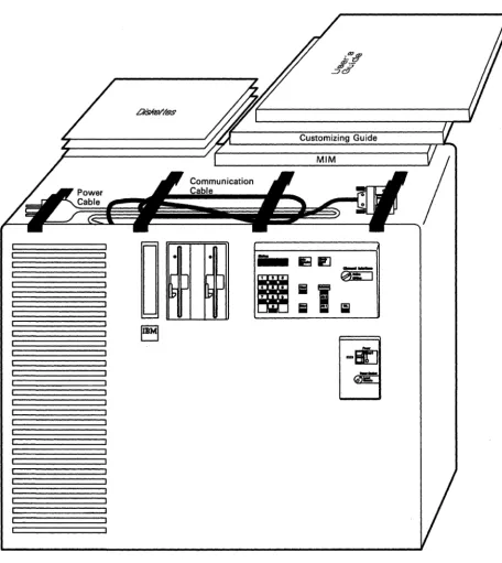
The next four figures identify ports and cables, and show sample cabling layouts, for Models IR and 2R (Figure 2-6), Model 3R (Figure 2-7 on page 2-9), Model lL (Figure 2-8 on page 2-10), and ASCII panels in the rear of the control unit (Figure 2-9 on page 2-11). For additional connector details, see "3174 Cables, Plugs, and Accessories" on page B-24.
Port 0
To Token-Ring Access Unit
Ports 0-7 (Terminal cables not shown) Ports 8-15
r - - - - Terminal Adapter/TMA Jumper Cables
To Modem
EIA, X.21, or V.35 connector
on Type 1 or 2 Communication Adapter (slot 22) Terminal Adapter Ports 0, 8, 16, 24 (slot 21 or 23 for Models 1 Rand 2R)
To Terminal or 3299 Terminal
Multiplexer (Ports 24-31)
3299 Terminal Multiplexer
Cable from
Terminal Adapter Port 16
Figure 2-6. Sample Cabling Layout for Models 1 Rand 2R
Ports 0-7 (Terminal cables not shown) Ports 8-15
3174 Ports and Cables
, - - - - Terminal Adapter/TMA Jumper Cables
To Token-Ring Access Unit
Port 0
Token-Ring Adapter (slot 11 )
Figure 2-7. Sample Cabling Layout for Model 3R
Terminal Adapter Ports 0, 8, 16, 24 (slot 21, 22, or 23 for Model 3R)
/
To Terminal or 3299 Terminal
Multiplexer (Ports 24-31)
3299 Terminal Multiplexer
Cable from
Terminal Adapter Port 16
3174 Ports and Cables
Bus and Tag receptacles (cables not shown)
To Token-Ring Access Unit
Token-Ring Adapter (slot 12)*
Ports 0- 7 (Terminal cables not shown) Ports 8-15
r - - - Terminal Adapter/TMA Jumper Cables
Terminal Adapter Ports 0, 8, 16, 24 (slot 21, 22, or 23 for Model 1 L)
/
To Terminal or 3299 Terminal
Multiplexer (Ports 24-31)
3299 Terminal Multiplexer
Cable from
Terminal Adapter Port 16
• Only in control units with the IBM Token- Ring Network 3270 Gateway feature.
Figure 2-8. Sample Cabling Layout for Model lL
To 3270
Host
3174 Models 1l, 1 R, 2R, 3R
D
o@ 1 2 if}) o@ 1 2
f?J
o@ 1 2I I I I I I I I I I I
4 5 6 7 4 5 6 7 4 5 6
I I I I I I I I
22 23
3164
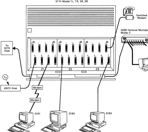
3174 Ports and Cables
Switched Modem
Note: This figure shows an overview of a 3174 with three Asynchronous Emulation Adapter features.
The terminals can be any of the ASCII terminals.
Figure 2-9. Sample ASCII Connection Diagram
3270 Terminal Port Addresses
3270 Terminal Port Addresses
This section explains how to determine a terminal's port address. To determine a terminal's port address (also known as port number), use the cabling worksheets and physical connection diagram for your subsystem to find how the terminal is connected to the 3174. (See Figure 3-3 on page 3-14 for an example of a cabling worksheet, and Figure 3-5 on page 3-17 for an example of a physical connection diagram.)
There are two ways that a terminal can be connected to the 3174:
• Directly, where the terminal is connected to a Terminal Adapter port (located in card location 22 or 23)
• Indirectly, where the terminal is connected to a Terminal Adapter port via a 3299 or a TMA.
For Terminals Directly Connected to the Terminal Adapter
If a terminal is directly connected to the Terminal Adapter, its port number, or terminal port address, is the same as the Terminal Adapter port number. For example, if the terminal is connected to Terminal Adapter port 16, its terminal port address is 16.
For Terminals Indirectly Connected to the Terminal Adapter
If a terminal is indirectly connected to a Terminal Adapter port via a 3299 or a TMA, its port number, or terminal port address, is determined by adding the number of the Terminal Adapter port to which the ter-minal multiplexer is connected to the number of the 3299 or TMA port to which the terter-minal is connected. For example:
Terminal Adapter Port
o
8 16 24
2-12
3299 or
+
TMA Port+
2+
4
+ 3
+
7Terminal Port Address
2 12
19
Diskettes and Diskette Drives
Diskettes and Diskette Drives
This section describes the different diskettes used with the 3174 control unit, how to handle diskettes, and how to insert diskettes into, and remove them from, the diskette drive. In addition, this section provides information on diskette shipping, receiving, and long-term storage.
Description of 3174 Diskettes
A diskette (shown below) is a thin, flexible magnetic disk and a protective jacket, in which the disk is perma-nently enclosed.
Disk
Label Protective Jacket
Warning: Do NOT try to remove the flexible magnetic disk from its protective jacket (black).
The function of the diskette is to store information that the 3174 Subsystem Control Unit and attached 3l79G or 3290 display stations need for operation. The types of diskettes associated with the 3174 are the Control diskette, the Utility diskette, the Downstream Load (DSL) diskette, the RPQ diskette, and the Encrypt/Decrypt diskette.
The Control diskette is used for the daily operation of the 3174. This diskette contains operational microcode and configuration information that is unique to your organization. For example, the Control diskette con-tains information that describes all terminals attached to the 3174.
The Utility diskette contains the microcode necessary to run various control unit utilities, including customization and offline tests (diagnostics).
The DSL diskette is used with the Control diskette for the daily operation of the 3174 when 3l79G or 3290 display stations are attached or when the AEA feature is installed. This diskette contains test and configura-tion informaconfigura-tion that is unique to your organizaconfigura-tion.
The AEA diskette contains Asynchronous Emulation Adapter code, which is to be merged onto the DSL diskette when the AEA feature is installed in the control unit. 3290 display stations are attached. This diskette contains test and configuration information that is unique to your organization.
The RPQ diskette contains the changes or additions to the functional capabilities of the 3174 to fulfill your unique data processing requirements.
The Encrypt/Decrypt diskette is used to enter and verify the Master Key Value in 3174 Models lR, 2R, and 3R.
Diskettes and Diskette Drives
How to Handle Diskettes
Follow the required diskette-handling procedures as shown here. Remember that a telephone is a source of a magnetic field.
Felt- Tip Pen
Do not bend
2-14
L
~
0,
o
Correct
Grip by the corner
Incorrect
No Pencils, No Clips, No Ball-Point Pens,
Not Much r;:::==+;:=~
Pressure
No Magnets
When Not in Use
Do not touch the disk
Diskettes and Diskette Drives
How to Insert and Remove Diskettes
These procedures describe how to insert diskettes into, and remove them from, the diskette drives. Diskette drive 1 is shown throughout these procedures. The diskette being inserted may be any valid control unit diskette.
Diskettes for the control unit are kept in the storage pocket next to the diskette drive(s).
Inserting Diskettes
1
Remove the diskette from the protective envelope.2
Make sure that the drive lever is up.Holding the diskette by the label with the label facing left, insert the diskette into drive I (left drive). Close the drive lever.
I
Insert
•
•
Close
•
Diskettes and Diskette Drives
Removing Diskettes
Warning: Do not remove a diskette while the diskette drive is turning. Make sure that the red indicator on the diskette drive is not lit before you remove diskettes.
1
Open the lever to diskette drive I (left drive). Grip the diskette by the label, and remove the diskette from the drive.2
Place the diskette in the protective envelope.DiskeHe Shipping and Receiving
•
•
•
{
Diskettes should always be shipped inside the original shipping container; an ordinary envelope does not provide enough protection. Label the package DO NOT EXPOSE TO EXCESSIVE HEAT (temperatures above 5IS C or 125° F) OR DIRECT SUNLIGHT.
Upon receiving diskettes, check for damage to the shipping container or to the diskettes. Save the shipping container for storing the diskettes for later shipment.
Long-Term Storage of Diskettes
Place diskettes in their protective envelopes, and store them in the following environment: • Temperature: 10° to 51SC (50° to 125°F)
• Relative humidity: 8% to 80%.
Before using a diskette that has been exposed to temperatures outside the above environment range, allow the diskette to adjust to room temperature for 5 minutes. The diskette can be removed from its shipping con-tainer while adjusting to room temperature, but should be kept in its protective envelope.
Making the 3174 Operational
Making the 3174 Operational
An Initial Microcode Load (IML) sequence causes some basic control unit tests to run. If these tests run without error, microcode is loaded from the diskette drive that has a customized Control diskette correctly installed and the drive lever closed. If you have two diskette drives, the Control diskette should be in drive 1. If you have a Downstream Load (DSL) diskette, it should be in drive 2.
You can start a normal IML in one of two ways:
• Press IML while power is on (for Model 1L, the Offline indicator must be lit) . • Turn on the 3174 (also called a
power-on
IML).To IML the 3174, do the steps listed for your 3174 model number.
If you get unexpected results at any time, refer to Figure 3-1 on page 3-3.
For Model1L
The following procedures describe how to IML the Model 1L when power is off (green dc indicator not lit -see "How to IML When Power Is Off"), and when power is on (green dc indicator lit - -see "How to IML When Power Is On" on page 2-19).
How to IML When Power Is Off
1
Make sure that a customized Control diskette is correctly installed in diskette drive 1 (refer to "How to Insert and Remove Diskettes" on page 2-15).If you have a DSL diskette, make sure that it is in drive 2.
Control
diskette
DSL
diskette
Making the 3174 Operational
2
3
4
Turn the Channel Interface to Online.
Turn the Power Control switch to Local.
Lift the Power switch to Start, and release it (it returns to the I position). This starts a normal IML. IML progress codes should appear in the Status display. IML takes about 4 minutes, and is completed when 501 appears in the Status display.
If required, notify the host operator to bring the 3174 online, at which time 3174 will be dis-played.
5
If your control unit has a Sequence and Control cable for remote power control of the control unit (see Figure 2-4 on page 2-5 for cable location), set the Power Control switch to Remote.2-18
Channel Interface
~
Power Control
~
How to IML When Power Is On
1
Make sure that a customized Control Diskette is correctly installed in diskette drive 1 (refer to "How to Insert and Remove Diskettes" on page 2-15).If you have a DSL Diskette, make sure that it is in drive 2.
2
Is the Offline indicator lit? Yes - Go to step 3.No - Turn the Channel Interface switch to Offline, and wait up to 30 seconds. If the omine indicator lights, go to step 3. If the omine indicator does not light, refer to "Forcing the Control Unit Omine" on page 3-11.
3
Press and release IML. This starts a normal IML. IML progress codes should appear in the Status display. Continue with step 4.4
Set the Channel Interface switch to Online (the omine indicator may turn off). IML takes about 4 minutes, and is completed when 501 appears in the Status display.If required, notify the host operator to bring the 3174 online, at which time 3174 will be dis-played.
Control
diskette
Channel Interface
Making the 3174 Operational
DSL
diskette
'<s\Online
1
\ . : ... -,:J...;O;..;f.;.;.fl
i~n.;;..e
_Cl--l+---
Lit?
Channel Interface
~
Making the 3174 Operational
For Models 1
R, 2R,
and 3R
If you get unexpected results at any time, refer to Figure 3-1 on page 3-3.
1
Make sure that a customized Control Diskette is correctly installed in diskette drive I (refer to "How to Insert and Remove Diskettes" on page 2-15). If you have a DSL Diskette, it should be in drive 2.2
Is the green dc power indicator lit?No - Lift the Power switch to the I posi-tion. This starts a normal IML.
Yes - Press and release IML. This starts a normalIML.
2-20
IML progress codes should appear in the Status display. IML takes about 4 minutes, and is completed when 501 appears in the Status display.
If required, notify the host operator to bring the 3174 online, at which time 3174 will be displayed.
Control
diskette
de indicator
~
I
o
DSL
Taking the 3174 Offline
Taking the 3174 Offline
To take the 3174 offiine, do the steps listed for your 3174 model number.
For Model1L
1
Notify the host operator to take the control unit offline.Set the Channel Interface switch to Offline, and wait up to 30 seconds for the offline indicator to light.
2
Did the offline indicator light?No - Refer to "Forcing the Control Unit Offline" on page 3-1l.
Yes - The system is now offline.
You can now do either a or b:
Channel Interface
'<s\~nline
1
~",,-*,:)_O;..ff~l_in_e _ _ CJ ___
+---
Lit?
a. Turn off the control unit by setting the Power switch to
O.
b. Leave power on and do either customizing or offline testing (see "Offline Tests" on page 3-108).
To make the system operational again, refer to "Making the 3174 Operational" on page 2-17.
For Models 1 R, 2R, and 3R
1
Notify the host operator to take the control unit offline.2
You can now do either a or b:a. Turn off the control unit by setting the Power switch to
O.
b. Leave power on and do either customizing or offline testing (see "Offline Tests" on page 3-108).
To make the system operational again, refer to "Making the 3174 Operational" on page 2-17.
Displaying the Master Menu
Displaying the Master Menu
The Master Menu presents all the utility functions available on the Utility diskette. This menu is used prima-rily for customizing.
Notes:
1. A 3278 or similar terminal must be attached to port 0 and turned on. 2. This procedure interrupts all host services. Notify users if necessary.
To display the Master Menu, do the following steps:
1
Ask the host operator to take the control unit offline.Insert a Utility Diskette into diskette drive l.
For Model IL, go to step 2.
For Models IR, 2R, and 3R, go to step 3.
2
Set the Channel Interface switch to Offline, and wait for the offline indicator to light.Note: If the offline indicator does not come on, refer to "Forcing the Control Unit Offline" on page 3-11.
3
Press and hold down Ait 1 while you press and release IML. Then release Ait 1.Notes:
2-22
I. If power is off, lift and release the Power switch instead of pressing IML.
2. If 40 does not appear in the Status display within 5 seconds, repeat this step.
Utility
diskette
Operator Panel
Stah.l8
I I I
4
When 40 appears in the Status display, press and release Enter.5
When 7000 appears in the Status display, the Master Menu is displayed at the terminal attached to port O. Refer to the 3174Custom-izing Guide for more operating information.
Displaying the Master Menu
Operator Panel
When you s
$ _
~EJ
ee
:I",p-lrm
,
2 34 5 6
Ii
7 8 9
i
-
LJii
-~ ~...
~
Press Enter
______ Master Menu ____ __
Microcode COPYRIGHT IBM CORP
Select Option: press Enter
1 Customize the Control Diskette 2 Merge DSL
3 Copy files 4 Diagnostics
5 Microcode Upgrade
6 Encrypt/Decrypt Master Key K Identify Customizing Keyboard
Select==> _
encrypt/decrypt Battery
Replacing the Encrypt/Decrypt Adapter BaHery
Sometimes, you may have to replace the battery for the Encrypt/Decrypt feature. The following instructions show you where the battery is located and how to replace it.
Notes:
1. You DO NOT need to tum off the control unit to replace the battery. If, however, you do tum off the control unit to replace the battery, you must reenter the master key value.
2. When throwing away the replaced battery, observe the disposal instructions on the battery label.
1
Open the front door of the 3174.The battery for the Encrypt/Decrypt feature is located on the front of the Encrypt/Decrypt adapter card (location 24).
2
Disconnect the battery connector from the card.2-24
Power
-B[]
11121314151117.18192021., 24 \ _ _ _ ....
3
Remove the old battery from the clip on the card.4
Insert the new battery into the clip, connect the new battery connector to the card, and close the front access door.Grip here
encrypt/decrypt Battery
Control Unit Problem Determination
Offline Tests 3-108 Test Operations 3-108 Alt 2
IML
Tests 3-108 Alt IIML
Tests 3-110Communication Adapter and Communication Cable Test 3-110 Token-Ring Adapter and Cable Test 3-114
Start Problem Determination Here
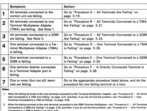
Initial Symptoml Action Table
The problem symptoms in the Initial Symptom/Action Table (Figure 3-1) are arranged in the order that they should be examined. Read down the list of symptoms until you find the first one that compares with an error condition in your system. Then do the recommended actions.
SYlllptom Action
1
Control unit does not power-on (green dc power indicator is not Go to "Checking Control Unit Power" on page 3-7.lit) .
2
other than a number, 0-9) in Nonnumeric character (something Request service for the control unit.Status display.
3
Status code in Status display, or at the terminals. code, and do the recommended actions. If the status Go to "Status Code Chart" on page 4-4, find the statuscode is not listed, request service for the control unit.
4
status code displayed). Check Cond indicator is lit (no Go to "Check Cond Indicator Lit and No Status Code" on page 3-10.5
The operator panel is not working correctly. For example: Request service for the control unit.• A Normal IML occurs when Ait 1 or Alt 2 IML is done • The 40 prompt after an Alt 1
IML does not display
·
Status code 1 30 is displayed when an Alt 1 or Alt 2 IML is done.6
Terminal or host connection problems. This includes: Go to "Symptom/Decision Chart" on page 3-4.·
Communication or link prob-lems to or from the 3174 control unit·
Direct-connect or cable prob-lems between the 3174 control unit and a terminal, station, or host.7
Symptom undefined. tests (refer to "Alt 2 IML Tests" on page 3-108). If the control unit is not working correctly, run Ait 2 1M LWarning: An IML disrupts all operating terminals.
If needed, request help from your technical support group or help desk.
Figure 3-1. Initial Symptom/Action Table
Make Problem Decision Here
Symptom/Decision Chart
The problem symptoms in the Symptom/Decision Chart (Figure 3-2) are arranged in the order that they should be examined. Read down the list of symptoms until you determine the first one that compares with the error condition in your system. Then GO TO the appropriate Symptom/Action Table or ask for help, as indicated.
TERMINAL CONNECTION PROBLEMS
1
3270-Type Terminal Connection ProblemThe connection between the control unit and a 3270-type terminal is failing.
Control Unit
Adapter 3270
HG 26 Terminal
A bad connection is indicated at a display station by a missing S, 4, or 6 in the lower left corner of the operator information area, and at a printer by a status code 27 or 28 or by the control unit signal's being off (refer to your printer manual).
GO TO "3270 Terminal Connection Problems" on page 3-13.
2
ASCII-Type Terminal Connection ProblemThe connection between the control unit and an ASCII-type terminal is failing.
Control Unit
ASCII ASCII
Adapter Terminal
HG 2X
2X = 21,22, or 23
A bad connection is indicated at an ASCII display station by a missing Connection Menu, or other messages, such as log on, sign on, or ready. For a display or printer, check your local operating instructions for the desired indication of a successful or failing connection.
GO TO "ASCII Terminal Connection Problems" on page 3-49.
Figure 3-2 (Part 1 of 3). Symptom/Decision Chart
Make Problem Decision Here
HOST CONNECTION PROBLEMS
3
Remote IBM Host Connection ProblemThe connection between the control unit and the remote IBM host is failing:
Control Unit
IBM Adapter
Host HG 11
A bad connection is indicated at the control unit by a 3XX or 5XX code in the Status display.
GO TO "Procedure G - A Remote Host Connection Is Failing" on page 3-43.
4
Local IBM Host Connection ProblemThe connection between the control unit and the local IBM host is failing.
Control Unit
IBM Adapter
Host HG16
A bad connection is indicated at the control unit by a 3XX or 5XX code in the Status display.
Request service for the control unit.
5
ASCII Host Connection ProblemThe connection between the control unit and an ASCII host is failing.
Control Unit
ASCII ASCII
Host Adapter
HG 2X
2X = 21, 22, or 23
GO TO "Selecting an ASCII Host System Symptom" on page 3-90.
Figure 3-2 (Part 2 of 3). Symptom/Decision Chart
Make Problem Decision Here
TOKEN-RING PROBLEMS
6
Token-Ring Connection ProblemThe connection to the Token- Ring is failing. This is indicated by a 3XX or 8XX Status code (at the display station; for Gateway, however, the Status code is shown in the control unit operator panel only).
GO TO HToken- Ring Adapter and Cable TestU on page 3-114.
Figure 3-2 (part 3 of 3). Symptom/Decision Chart
Checking Control Unit Power
Checking Control Unit Power
You are here because the green dc power indicator is off.
For Model lL, do the steps listed below. For Models lR, 2R, and 3R, go to page 3·8.
For Model1L
1
2
3
Turn the Power Control switch to Local.
Lift the Power switch to Start, and release it (it returns to the I position).
Is the green dc power indicator lit?
No - Go to "Checking AC Power" on page 3-9.
Yes - Is there a Sequence and Control cable?
No - Close the front door and con-tinue normal operation.
Yes - Turn the Power Control switch to Remote, and close the front door. Go to step 4.
Power Control
~
G25
LocalRemote
dc indicator
~~
Power Control
,.
; Remote
~J
Local4
Did the green dc power indicator remain lit?No - Make sure that the Sequence and Control cable is installed correctly, and that the host is operating normally. Then go back to step I and try this procedure again. If you do not find the problem, request help from your technical support group or help desk.
Note: As a temporary measure, you can set the Power Control switch to Local and turn on power.
Yes - Continue normal operation.
Checking Control Unit Power
For Models 1 R, 2R, and 3R
1
Is the Power switch set to 1 ? No - Lift the Power switch to I.Yes - Go to step 2.
2
Is the green dc power indicator lit?3-8
No - Go to "Checking AC Power" on page 3-9.
Yes - Continue normal operation.
dc indicator
Cbecking Control Unit Power
Checking AC Power
You are here because the Power switch is set to I, but the dc power indicator is not lit.
1
Press the latch-release pushbutton on the left-center edge of the front door, open the door, and check the green ac power indicator. Go to