N A N O E X P R E S S
Open Access
Scan speed control for tapping mode SPM
Aleksey V Meshtcheryakov
1*†and Vjacheslav V Meshtcheryakov
2*Abstract
In order to increase the imaging speed of a scanning probe microscope in tapping mode, we propose to use a dynamic controller on‘parachuting’ regions. Furthermore, we propose to use variable scan speed on‘upward step’ regions, with the speed determined by the error signal of the closed-loop control. We offer line traces obtained on a calibration grating with 25-nm step height, using both standard scanning and our scanning method, as
experimental evidence.
Keywords:tapping-mode SPM, scan speed, closed-loop control
Background
Tapping mode is considered to be the most precise mode of the scanning probe microscope [SPM] [1-4]. The main disadvantage of this SPM mode is low perfor-mance; it takes a long time to obtain the topographic image of the sample surface. The main limiting para-meter of increasing imaging speed in tapping mode is the time constant [τc] of the cantilever. In contact mode,
this limitation is absent. This fact allows the imaging speed to be higher when using, for instance, a high-speed piezoelectric stack actuator [5,6]. However, it’s desirable to use tapping mode in many instances since it reduces the lateral forces exerted by the tip on the sam-ple, thereby reducing tip-sample wear [1,4].
The following methods are known to reduce scanning time:
1) The cantilever resonant frequency [ω0] is increased by reducing cantilever size (and mass) and increasing its stiffness. However, this can be done only by completely changing the probe construction [1].
2) The cantilever quality factor [Q] is reduced by means of cantilever external excitation. In this instance, the total signal consists not only of the excitation signal but also of an extra component proportional to the speed of the can-tilever deflection. Reducing the cancan-tileverQfactor, how-ever, will result in a reduction in the image resolution [3].
3) A dynamic controller (a switching gain propor-tional-integral [PI] controller) is used on the base of the error signal which increases in a ‘parachuting’ region [2,4].
The scan speed is assumed constant in each of the above instances. A variable-speed scanning method [7] allows the determination of the scan speed value accord-ing to a particular transient response of the PI controller output signal.
In the present paper, we used both the dynamic con-troller method and variable-speed scanning to obtain the topographic image of the sample surface. In contrast to Zhang et al. [7], the scanning speed was determined by the behavior of the error signal controls (which was the input signal for the PI controller). The PI controller output bandwidth can be determined from the time constant of the loop control. The error signal bandwidth can be determined from the time constant of an AM (or FM) detector of the probe deflection signal. This time constant is an order of magnitude smaller than the time constant of the loop control [1-4]. This allows faster adaptation of the scan speed to a particular sample sur-face topography.
Methods
The cantilever oscillation amplitudeA(t), while scanning a step of heightΔz, is expressed as [1]
A(t)=Asp+z·
1−exp−ω0t/2Q
, (1)
whereω0is the cantilever resonant frequency,Qis the cantilever quality factor, andAsp is the set point ampli-tude. Thus, the cantilever transfer functionC(s) takes
* Correspondence: [email protected]; [email protected]
†Contributed equally
1Faculty of Automation and Electronics of the National Nuclear Research
University (MEPhI), Moscow, 115409, Russia
2Department of Physical and Mechanical Properties Research of Federal State
Institution, Technological Institute for Superhard and Novel Carbon Materials, Troitsk, 142190, Russia
Full list of author information is available at the end of the article
the form C(s)= 1
(1 +sτc)
, whereτc is the time constant
of the cantilever and is equal to τc= 2Q ω0
. The frequency
response of the actuatorG(s) and the cantilever deflec-tion signal detectorK(s) has a constant gain equal to DC gain and don’t add extra phase lag (it can be assumed thatG(s)·K(s)· =G0·K0 ≈1) in the bandwidth of interest. Indeed, the pole frequency of the detector transfer function [ωdet] should be at least ten times less than the cantilever resonant frequency ωdet=ω0
10.
The pole frequency of the transfer functionC(s) is equal to τc−1=ω0
2Qωdet (if Q∼100).
Suppose the feedback controller is an integral control-ler with time constantτiwhose transfer functionR(s) is
R(s) =− 1
sτi
. Then, the frequency-dependent open-loop
gain becomes
−sτ1
i ·
G0·K0· 1 (1 +sτc)
. Thus, the
characteristic polynomial of the loop control’s frequency responseD(s) can be written as
D(s) =s2+ 1
τc
s+G0K0
τcτi ≈
s+ 1
τc
s+G0K0
τi
. (2)
For stability of the loop control, we need to have sig-nificantly different frequencies for the real poles of the transfer function:
G0K0
τi 1
τc
. (3)
In the case of such characteristic polynomials, the transient response is described by two exponential func-tion, the fast function having time constant τc and the
slow function, τi
G0K0. As a result, the speed of a closed-loop control system (that is, without loss of surface) is
determined by the time constant τi
G0K0. Feedback speed, the speed of the actuator, is limited in tapping mode by the stability condition of the loop control (Equation 3). Thus, the feedback speed is limited by the cantilever time constantτc.
Increasing scan speed leads to a loss of surface when a
‘downward step’is scanned or a parachuting effect. If an
‘upward step’ is scanned, it leads to instability of the loop control [1,2].
Let us find the maximum scan speed without loss of surface. The transient response of the loop control to a capacitive displacement sensor output (if the high-fre-quency pole (frehigh-fre-quencyτ−1
c , Equation 2) is ignored) can
be written as
Y(s)
Z(s) =
1
1 +sτi
G0K0
. (4)
Then, the transient response of the loop control for a downward step of heightΔztakes the form
y(t)=z·
1−e−G0K0t
τi
. (5)
In the latter case the initial vertical actuator speed is
υv=
y(0)
t =
z·G0K0
τi
. (6)
Assuming that there is no loss of surface by the probe, the horizontal scan speed υH is related to the vertical
actuator speedυvby
υH=υv·tg
a
2
= z·G0K0·tg
a
2
τi
, (7)
whereais the apex angle of the diamond tip.
From Equation 3, it follows τi G0K0 ≈
10τc= 20·Q
ω0 yielding
υH=
z·ω0·tg
a
2
20·Q (8)
An increase in the actuator speed is caused by an increase in the error signale(t) =A(t) - Asp. For a step of heightΔz<Afr-Asp, whereAfris the free-air amplitude (the amplitude of the cantilever oscillation without touching the surface), the error signal is e(0) = Δz. That’s why the velocity υH depends on the step height Δz. ForΔz= (Afr-Asp), the scan speed becomes
(υH)lim=
Afr−Asp
·ω0·tg
a
2
20·Q . (9)
For higher steps, the initial probe speed doesn’t increase as the error signal is saturated atemax = Afr-Asp. For scan speedυH > (υH)lim, the tip doesn’t touch
the surface and loses sample surface.
For example, let us find the scan speed limit for the SPM NanoScan-3D [8] where the probe is a piezocera-mic cantilever with a diamond tip. This device allows you to scan the surface topography and to produce indentation and sclerometry simultaneously. If the set point amplitude is Asp= 0.8·Afr (where the cantilever free-air amplitude isAfr = 100 nm), the cantilever reso-nance frequency is f0 = 11.5 kHz, the quality factor is 100, and the apex angle of a diamond tip is 120° [8], then the scan speed limit is approximately (υH)lim≈ 12.5
The loop control is a high-pass filter for the error sig-nal which is related to the height step Δz by
e(t)=z·K0·e −tG0K0
τi . In the case of parachuting, the
[image:3.595.57.547.90.639.2]loop control is opened by the loss of sample surface by the probe. The error signal is saturated atemax= (Afr-Asp)≈0.2Afr. To avoid, or at least reduce, the parachut-ing region, the dynamic controller should increase the
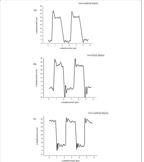
Figure 1The line traces of the calibration grating with the step height equal to 25 nm. At a constant speed of 30μm/s (a), with a
error signal emax [2] or reduce the integral controller time constantτi.
According to the algorithm implemented on FPGA, if the error signal is more than a thresholdeth, the integra-tor time constant is reduced according to
τi(t)=τi−g·(e(t)−eth), (10) wheregis the‘gain’of the dynamic controller.
As the tip scans over an upward step, the probe oscil-lation amplitude is reduced. It can be reduced to zero for the height stepΔz>Asp and scan speedυH> (υH)lim (Equation 9). A higher scanning speed can damage both the sample and the tip. A decrease of the time constant τi can cause instability of the closed-loop. According to
the found algorithm, the scanning speed is reduced for the threshold of the amplitude Alow<Asp. Scanning at the lower speed is continued as long as the error signal is reduced and the oscillation amplitude is restored.
Results and discussion
A calibration grating with a step height of 25 nm was used as the sample. A line trace with constant scan speed of 30μm/s is shown in Figure 1a. A typical scan has a parachuting over a downward step and a peak over an upward step.
The time constant of the implemented dynamic con-troller is four times decreased in the parachuting region. Figure 1b shows a scan line trace using the algorithm of the dynamic controller. There is practically no parachut-ing, as shown in the figure. However, the peak over the
upward step stayed. In addition, there formed another peak due to a significant increase in the error signal of the loop control after the probe reached the bottom after a downward step. It was decided to reduce the scanning speed in this region.
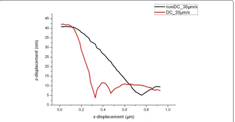
Figure 1c shows the line over a downward step trace in the case of a dynamic control and over an upward step for a variable scanning velocity. For a detailed comparison, Figure 2 shows a part of the line traces (parachuting region) in the case of the usual scanning with a constant speed of 30μm/s and in the case of using dynamic control with variable scanning velocity. For dynamic control, the length of parachuting is reduced by three times.
Conclusions
The novelty of the presented scanning method consists of using a dynamic controller on a downward step and variable scan speed on an upward step, with scan speed determined by the magnitude of the error signal. As the experimental data on a calibration grating show, assum-ing equivalent image quality, our method has an advan-tage of up to three times in imaging speed.
Acknowledgements
The authors would like to thank the Federal target programme Research and Pedagogical Cadre for Innovative Russia for 2009-2013 (grant no 14.740.11.1449) for providing financial support to this project.
Author details
1Faculty of Automation and Electronics of the National Nuclear Research
[image:4.595.58.542.89.340.2]University (MEPhI), Moscow, 115409, Russia2Department of Physical and
Mechanical Properties Research of Federal State Institution, Technological Institute for Superhard and Novel Carbon Materials, Troitsk, 142190, Russia
Authors’contributions
AVM and VVM contributed equally to this work. All authors read and approved the final manuscript.
Competing interests
The authors declare that they have no competing interests.
Received: 30 September 2011 Accepted: 14 February 2012 Published: 14 February 2012
References
1. Sulchek T, Yaralioglu GG, Quate CF:Characterization and optimization of scan speed for tapping-mode atomic force microscopy.Rev Sci Instrum 2002,73(8):2928-2936.
2. Kodera N, Sakashita M:Dynamic proportional-integral-differential controller for high-speed atomic force microscopy.Rev Sci Instrum2006, 77:083704.
3. Orun B, Necipoglu S, Basdogan C, Guvenc L:State feedback control for adjusting the dynamic behavior of a piezoactuated bimorph atomic force microscopy probe.Rev Sci Instrum2009,80:063701.
4. Agarwal P, De T, Salapaka MV:Real time of probe-loss using switching gain controller for high speed atomic force microscopy.Rev Sci Instrum 2009,80:103701.
5. Zhao B, Howard-Knight JP, Humphris ADL, Kailas L, Ratcliffe EC, Foster SJ, Hobbs JK:Large scan area high-speed atomic force microscopy using a resonant scanner.Rev Sci Instrum2009,80:093707.
6. Fleming AJ, Kenton BJ, Leang KK:Bridging the gap between conventional and video-speed scanning probe microscopes.Ultramicroscopy2010, 110(9):1205-1214.
7. Zhang Y, Fang Y, Yu J, Dong X:Note: a novel atomic force microscope fast imaging approach: variable-speed scanning.Rev Sci Instrum2011, 82:056103.
8. Useinov A, Gogolinskiy K, Reshetov V:Mutual consistency of hardness testing at micro- and nanometer scales.Int J Mater Res2009,7:968.
doi:10.1186/1556-276X-7-121
Cite this article as:Meshtcheryakov and Meshtcheryakov:Scan speed
control for tapping mode SPM.Nanoscale Research Letters20127:121.
Submit your manuscript to a
journal and benefi t from:
7 Convenient online submission
7 Rigorous peer review
7 Immediate publication on acceptance
7 Open access: articles freely available online
7 High visibility within the fi eld
7 Retaining the copyright to your article