Image Stitching using Harris Feature Detection and
Random Sampling
Rupali Chandratre
Research Scholar, Department of Computer Science,
Government College of Engineering, Aurangabad, India.
Vrishali Chakkarwar
Asst. Professor, Department of Computer Science, Government College of Engineering, Aurangabad,
India.
ABSTRACT
In this paper the problem of fully automated panoramic image stitching for 2D image is introduced. In this work, stitching two images using invariant local features is used. This algorithm recognises multiple panoramas in an unordered image dataset and uses Harris Corner Detection for detecting the key point i.e. features. RANSAC method is used to choose the closest match between the two images by separating inliers and outliers. For the Image stitching using the inliers, homography matrix is used which requires least 8 feature points . Once the homography matrix is calculated between the two images, a panoramic view by wrapping the two images is generated. To get the efficient homography matrix, the feature points which fall onto the corresponding epipolar lines are selected. In this rectilinear projections are used to project the resulting image. In rectilinear projections images are viewed on two dimensional planes. Harris Corner Detection method is more robust for detecting the corners in the images than other methods. Hence, Harris Corner Detection with RANSAC which gives efficient image stitching.
KEYWORDS
Harris Corner detector, Panoramic view, Perspective transform, rectilinear projection, Feature points, Key points
1.
INTRODUCTION
Image stitching is the process generating single image from a series of smaller, overlapping images. Image stitching is used in application areas such as interactive panoramic viewing of images, architectural walk-through, multi-node movies and other applications associated with modelling the 3D environment using images acquired from the real world[1].
The basic geometry of the problem consists of estimating a 3 × 3 matrix or homography for the input images. Homography estimation process requires an initialisation, which is provided by user input to calculate approximately align the images, or a fixed image ordering.
In the research literature methods for automatic image alignment and stitching is categorised into two types [1],
The one is direct based and the second is feature based. Direct methods gives very accurate registration because they have key use for all of the input image data, but if they don't have a close initialisation then it will fail[4]. Other case is in the Feature based, in this registration does not need any type of initialisation [3]. But it includes the traditional ways for feature matching methods which doesn't have the invariance properties. Those are necessary for enabling reliable matching for the input images for Panorama [11][13].
In this work it has described feature based approach to automatic panoramic image stitching is described. Firstly, the paper included Harris Corner Detector method for invariant
features detection in the input images. Secondly, by viewing the feature points detected by Harris Corner method, it apply the RANSAC method for detecting the Inliers and Outliers in the images for stitching purpose, after that it apply the Homography Estimation taking the inliers and using the 3x3 matrix and then finally wrapped the two images into one to another one for stitching purpose. Thirdly, it generate high-quality results using multi-band blending to render seamless output panoramas. Paper also mentioned the bundle adjustment implementation.
The remainder of the paper is structured as mentioned next Section 2 implement the actual calculation methods of the Panorama problem and describes choices for invariant features. Section 3 describes image key points separation from Inliers to Outliers i.e. RANSAC method and a model for image match verification. In section 4 it present results, conclusions , acknowledgment and the future work.
2.
IMAGE STITCHING FOR
PANORAMA
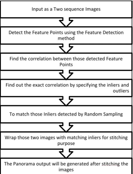
Fig 1: Flow chart of the Image stitching process
2.1
Harris Corner Detection
In Image processing, the feature points also called key points. It is the basic concept in the image processing, which is used in many techniques like object recognition, image registration, visual Object tracking and corner detection [19]. The Harris feature detector is the widely accepted and used method to detect feature points and to detect the corners from the input images. There are other methods also like Harris, SIFT [19]. But considering the speed the Harris Corner is the fastest than the SIFT.
To find the corners in the input image Harris method take look at the average intensity which is directional. The intensity change in the small specific area called window around an interested point. First it takes the displacement vector based on the (x, y) factor then calculate it with the average intensity change which is as shown in following Eq (1):
R=∑ (I (u+ x, v+ y)-I (u, y))2
---(1)
The average intensity change is calculated using the above expression. And the calculation will be in all directions of the input image. The point where the average intensity strongly high change as compared to the previous one direction is called as 'Corner'. Harris Detector method perform the corner detection using the next expression as shown in the Eq (2), which is obtained the direction of maximal average change of intensity. If the intensity change is strongly high in both the directions then the particular point is a Corner. This representation can be the average intensity change using Taylor expansion as below:
𝑅 ≈ (𝐼 𝑢, 𝑣 + 𝜕𝐼 𝜕𝑢𝑥 +
𝜕𝐼
𝜕𝑣𝑥 − 𝐼(𝑢, 𝑣) = ((𝜕𝐼
𝜕𝑢𝑥)2 + 2 𝜕𝐼 𝜕𝑢
𝜕𝐼 𝜕𝑣𝑥𝑦)
R ≈ [x, y] (
δI
δu)2
δI
δu
δI
δv
δI
δu
δI
δv (
δI
δv)2
---(2)
There is also another way to show the Taylor expansion in matrix form that one is the covariance matrix which specifies the rate of change of intensity.
From this matrix it can be very easy to find the average intensity change in the specific direction and the specific direction orthogonal to the previous specific direction using the Eigen values which are calculated from the matrix. These values also can be applicable to detect the position of the point which is the point on the edge, region for homogeneous, corner. If one Eigen vector value is high and other Eigen vector value is low the point located on the edge line. If the both values of Eigen vector are having low intensity then the point is in the homogeneous region. If both values are high in the region then that point is corner.
There is no explicit calculation of the Eigen values in the Harris corner detection method, sum of those values squared differences matrix by solving for the below corner metric matrix, R as shown in the Eq (3):
R = AB − C2− 𝓀(A + B)2 ---(3)
The variable k related to the sensitivity factor. There is flexibility to specify its value using the Sensitivity factor (0<k<0.25) parameter. If the value of k is smaller, then it is more likely that the algorithm will detect sharp corners. It use the Coefficients for smoothing filter parameter used for defining a vector of filter coefficients. This block multiplies the vector of coefficients by taking its transpose to create a matrix of filter coefficients, w.
It require O(n log n) time by using a k-d tree to find approximate nearest neighbours. This k-d tree is an axis which is aligned binary space partition, and recursively partitions the feature space at the mean in the dimension with highest variance.
2.2
To set Relation of Feature Points in input
images
At this stage the main objective is to select all feature points which are matching on both the input images [16]. So that it will be helpful to overlap the images. Feature points are the nearest features i.e. Key points. By connecting those set of key points for the two images matches will later be the output in panoramic Image. When there are number of images for the Panorama, then the problem can occur about the potentially matching the input images. But still, there is necessary to match each and every image to overlap them using a small set of key points for a good solution in case of image geometry.
In this feature matching step, it takes the two input images that have a large number of matches between each other. Here one can use only two images, but when considering a constant number m images, those have the large number of feature points which matches to the current image, for potential or The Panorama output will be generated after stitching the
images
Wrap those two images with matching inliers for stitching purpose
To match those Inliers detected by Random Sampling Find out the exact correlation by specifying the inliers and
outliers Find the correlation between those detected Feature
Points
Detect the Feature Points using the Feature Detection method
thick image matches it should be m =6. In this paper it uses RANSAC to identify a set of inliers that makes compatibility with a homography between the input images. Next stage is to apply a probabilistic model to verify the match.
2.3
Homography
Estimation
using
RANSAC
RANSAC (Random Sample Consensus) method is a robust and widely used that calculate a minimal set of inliers which are correspondences to estimate image transformation parameters, and find a solution that has the very good consensus with the data. In the case of panorama functionality we select sets of four means r = 4 which are feature correspondences and compute the homography i.e. H between those inliers calculate it using Direct Linear Transformation (DLT) procedure .Then repeat this with 500 times i.e. n = 500 trials and then select the particular solution that has the maximum number of inliers i.e. for those projections are consistent with H within a tolerance E pixels. The probability will be given that a feature match will be correct between a pair of matching images that's called the inliers probability, is pi, and the probability of finding the correct transformation after n trials is p(H is correct)=1 − (1 − (pi)r)n .
After a 500 trials the probability for finding the correct homography will be very high. For example, pi = 0.5 is a an inliers probability and the 1 × 10⁻¹⁴ is a approximate probability that the correct homography is not found after 500 trials.
RANSAC method is essentially a sampling approach for calculation of estimating H.
2.4
Ideal Model for verification of Image
Match
For each pair of potentially matching images it has a set of inliers which are feature point matches those are geometrically consistent calculated by RANSAC and a set of Outliers which are features that are inside the area of overlap but not consistent also calculated by RANSAC. The main idea of the verification model is, it should compare the correct probabilities that set of inliers was generated by a correct image match or the set of outliers was generated by a false image match.
For a given input image it denote the total number of feature points in the overlapping area of two images, the Outliers i.e. nf and the Inliers i.e. ni. The specific event that those image matches correctly or incorrectly, the representation is done by the binary variable mE {0, 1}. The event that the ithfeature match f
(i)
E {0, 1} is an inliers or outlier is assumed to be independent B, so that the total number of inliers will be Binomial shown in the Eq (4).
p(f(1:nf )|m = 1) = B(ni; nf,p1)
p(f(1:nf )
|m = 0) = B(ni; nf,p0) ---(4)
where p1 is the probability of feature points which match correctly which is an inliers, and p0 is the probability a feature points is an outlier given a false image match. The set of feature match variables {f
(i)
,i =1, 2,...,nf } is denoted f(1:nf ). The
.n f
number of inliers ni = f(i) and B(.) is the Binomial i=1
distribution n! like in Eq (5).
B(x; n, p)= p x
(1 − p)n−x x!(n − x)! ---(5)
We choose values p1 =0.6 and p0 =0.1. So now it can evaluate the posterior probability for an image match is correct Once between the images pair wise correct matches have been established , it can easily find panoramic sequences using connected sets of feature points of images. This allows us to recognise multiple panoramas in a set of images, and reject noise images which match to no other images.
2.5
RANSAC for Inliers/Outliers
RANSAC (random sample consensus) uses a random sampling techniques, which generates the approach of parameter estimation to handle with a proportion of not matches feature points i.e. Outliers in the input image [12].
The basic Algorithm for the RANSAC is as follows [11]:
1) First select the minimal number of feature points randomly for the purpose of model parameters.
2) Solve those selected model parameters
3) Then it determines matches and non-matches between the selected parameters i.e. set of all the points which fi with a predefined tolerance E.
4) If the number of inliers fraction on the total number points in the given set goes higher than the threshold T, which is predefined, it estimate the model parameters using all the identified inliers and terminate.
5) If required then repeat step 1 to 4 maximum number of N = 500.
2.6
Homography Matrix
The homography matrix dimension is 3x3 which is related to the pixel which called coordinates from the two images. Suppose a one coordinate x1= (u1, v1, 1) from one image and x2= (u2, v2, 1) from second image then those both pixels are related with a matrix M. M matrix specifies the relation which is linear, this relation is between the image points from the two images. The matrix is shown as below Eq (6).
𝑢1 𝑣1
1 =
𝑚1 𝑚2 𝑚3 𝑚4 𝑚5 𝑚6 𝑚7 𝑚8 𝑚9
𝑢2 𝑣2 1
---(6)
2.7
Bundle Adjustment
If there is a set of matches which matched with geometrically consistent between the two images. Then use bundle adjustment for solving all of the parameters jointly. This is an basic and essential step for concatenation of pair wise homography, which would may cause error of accumulation and disregard multiple constraints between the two images, For instance, the ends of a Image Stitching should combine up. These two images are added to the bundle adjuster one by one, with the best matching image i.e. max number of consistent matches which then will be added at each and every step. The new image is initialised as the output single image to which it best matches. Then the parameters will be updated by using the Leven berg-Marquardt[10].
The objective function that it uses here is a robust for summing squared projection error. That is, each feature is focused into all the input images in which it matches, and then sum of squared image distances is minimised with respect to the parameters.
There is also possibility to represent the unknown ray directions which is X externally, and to calculate them jointly with the parameters. This will not be increase the complexity of the method if there is a sparse bundle adjustment method was used.
2.8
Panorama Output Straightening
After stitching the both image the output will be in the wavy. We can correct such wavy output and straighten the stitching panorama output by taking use of a heuristic, which is typical the way to shoot a purposefully panoramic [5]. The idea behind it is that, it's very rarely used from people to twist the camera relative to the horizon, so the X vectors which is horizontal axis typically lie down in a plane . By finding the vector of the covariance matrix which is null X vectors, we can also find the “up-vector” u means normal to the plane which contains the camera centre and its horizon as shown below Eq (7).
nXiXT u = 0. i=1 ---(7)
Applying a global rotation such that up-vector u is vertical (in the rendering frame) effectively removes the wavy effect from output panoramas.
2.9
Multi-Band Blending
Ideally each pixel from the input image along with a ray that would have the exactly same intensity in every image which it intersects, but in the reality this will not be the case[9]. Even after gain compensation there is possibility that some image edges will still visible due to a not well structured effects, for instance less intensity at the edge of the input image, parallax effects due to unwanted motion of the optical centre and non-registration errors due to wrong or non-modelling of the camera and radial distortion and so on. Because of this a good blending strategy is very important in Image stitching in Panorama.
3.
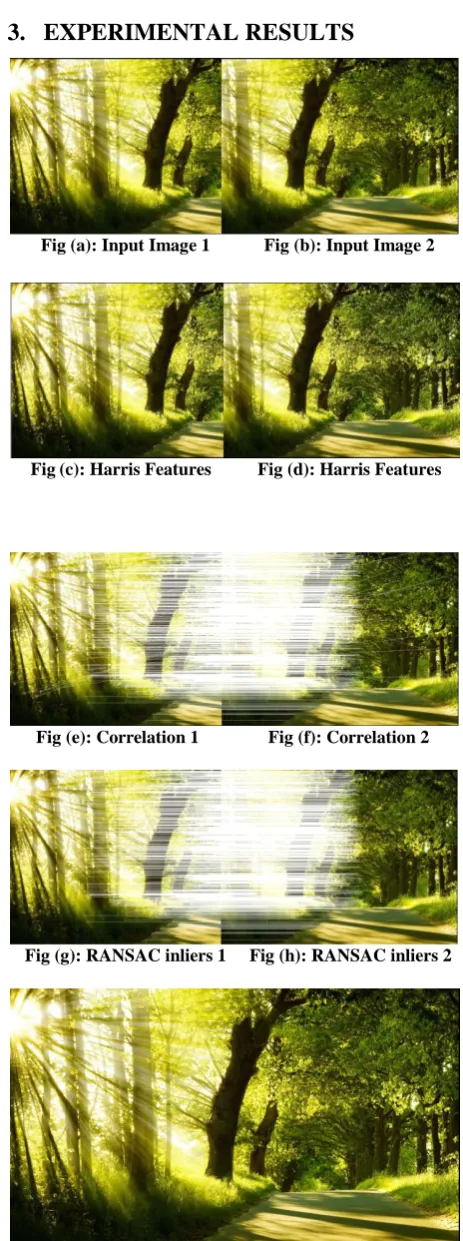
EXPERIMENTAL RESULTS
Fig (a): Input Image 1 Fig (b): Input Image 2
Fig(c): Harris Features Fig (d): Harris Features
Fig (e): Correlation 1 Fig (f): Correlation 2
Fig (g): RANSAC inliers 1 Fig (h): RANSAC inliers 2
Fig (i): Images stitched according to a homography
[image:4.595.312.544.63.684.2] [image:4.595.317.545.75.350.2]two images Fig (e) and Fig (f) is shows the correlation. Then we apply RANSAC method which differentiates the inliers and outlier, Fig (g) and Fig (h) shows the output for RANSAC.
And then Fig (i) shows the output after aligned the image according to the Homography. A set of images containing 1 panorama and 2 noise images was input. The algorithm detected connected components of image matches and unmatched images, and output 1 blended panorama.
4.
PERFORMANCE ANALYSIS
In Panorama image stitching, there is requirement for a good feature detector. Generally in panorama Harris and SIFT methods are used for detecting the features. Harris Corner detector is more efficient than SIFT because it detects isolated points. Also Harris feature detector is faster than SIFT method; the comparison of the speed is as shown in the Table 1.
Table 1: Speed Comparison of the Corner Detectors Lena Harris SIFT
ms 1024 3743
These isolated points are reasonably invariant to rotation, various sampling and quantization. The uses of the detector will be in tracking and finding correspondence between features. Hence Harris Corner Detector is chosen for this Panorama Stitching. After this RANSAC method is used to match the exact inliers. This uses to identify the nearest match features the inliers and outliers.
Combining the Harris and RANSAC together, the 2D image stitching becomes the powerful and robust tool to make the Image Panorama.
5.
CONCLUSION
This paper has presented a method of Image Stitching combining the Harris and RANSAC together which become the powerful tool to make the Panorama for 2D images.
Our use of invariant local features in Harris Feature Detection and a probabilistic model in RANSAC to verify image matches gives fast and fine technique as compare to SIFT. This work can allows us to recognise multiple panoramas in unordered image sets, and stitch them. A multi-band blending scheme ensures smooth transitions between images despite illumi-nation differences, while preserving high frequency details.
6.
FUTURE WORK
Future work includes work for straitening in the Output stitched image.
Image Straightening In Panorama Output [9] After stitching the 2D images there is necessity to straight or to align the output with the proper format as the output image is having wavy display view. For that it requires registration that uses the steps of the relative rotations, but it is having an unknown 3D rotation to choose coordinate frame. If we suppose assume that R = I for one of the input image, we then typically a wavy effect in the output panoramic image is found. Motion Panoramas often having problem from parallax errors due to tiny motions of the optical. These can be removed by doing for image translations and depths in the scene, before re-rendering from a central point. There is a good representation to use may be plane at infinity plus parallax.
7.
ACKNOWLEDGMENT
I thankful to my guide Prof. V. A. Chakkarwar, who has given me the great support and guidance for the paper Panorama. Her knowledge is really helpful for me in this work. I also thanks to my husband, my parents and my friends for their supports.
8.
REFERENCES
[1] P. Burt and E. Adelson. A multiresolution spline with application to image mosaics. ACM Transactions on Graphics, 2(4):217–236, 1983.
[2] J. Beis and D. Lowe. Shape indexing using approximate nearest-neighbor search in high-dimensional spaces. In Proceedings of the Interational Conference on Computer Vision and Pattern Recognition (CVPR97), pages 1000– 1006, 1997.
[3] M. Brown and D. Lowe. Recognising panoramas. In Proceedings of the 9th International Conference on Computer Vision (ICCV03), volume 2, pages 1218–1225, Nice, October 2003.
[4] D. Brown. Close-range camera calibration. Photogrammetric Engineering, 37(8):855– 866, 1971. [5] M. Brown, R. Szeliski, and S. Winder. Multi-image
matching using multi-scale oriented patches. In Proceedings of the Interational Conference on Computer Vision and Pattern Recognition (CVPR05), San Diego, June 2005.
[6] S. Chen. QuickTime VR – An image-based approach to virtual environment navigation. In SIGGRAPH’95, volume 29, pages 29–38, 1995.
[7] D. Capel and A. Zisserman. Automated mosaicing with super-resolution zoom. In Proceedings of the International Conference on Computer Vision and Pattern Recognition (CVPR98), pages 885–891, June 1998.
[8] J. Davis. Mosaics of scenes with moving objects. In Proceedings of the International Conference on Computer Vision and Pattern Recognition (CVPR98), pages 354–360, 1998.
[9] P. Debevec and J. Malik. Recovering high dynamic range radiance maps from photographs. Computer Graphics, 31:369–378, 1997.
[10]M. Fischler and R. Bolles. Random sample consensus: A paradigm for model fitting with application to image analysis and automated cartography. Communications of the ACM, 24:381–395, 1981.
[12] M. A. Fischler and R. C. Bolles. Random sample consensus: paradigms for model fitting with applications to image analysis and automated cartography. Commun. ACM, 24:381–395, June 1981
[13] D. Milgram. Computer methods for creating photomosaics. IEEETransactions on Computers,
C-24(11):1113 – 1119,1975
[14] R. Hartley and A. Zisserman. Multiview Geometry in ComputerVision. Cambridge University Press, 2004. H.-Y. Shum and R. Szeliski. Construction of panoramic imagemosaics with global and local alignment. Internal Journal of Computer Vision, 36(2):101–130, 2000
[16] M. Brown and D. Lowe. Automatic panoramic image stitching using invariant features. International Journal of Computer Vision,74(1):59–73, 2007
[17] M. Brown and D. Lowe. Recognising panoramas. In ICCV,2003 J. Jia and C.-K. Tang. Image registration with global and localluminance alignment. In ICCV,
2003
[18] W. Triggs, P. McLauchlan, R. Hartley, and A. Fitzgibbon. Bundle adjustment: A modern synthesis. In Vision Algorithms: Theory and Practice, number 1883 in LNCS, pages 298–373. Springer-Verlag, Corfu, Greece, September1999.