Pairing based Encoding Schemes (PBES) for Secure
Wireless Sensor Networks
Rohit Vaid
CSE Department M. M. Engineering College,
M. M. University,
Mullana, Ambala, Haryana, India-133207
Vijay Katiyar (Member, IEEE)
CSE Department M. M. Engineering College,
M. M. University,
Mullana, Ambala, Haryana, India-133207
ABSTRACT
Due to significant advancement in network technology, wireless information gathering communication system has attracted a great attention in recent years. Wireless sensor network (WSN) is also such type of information collecting system which works autonomously with the help of tiny sensors. These tiny sensors form a network in such a way that they not only sense the information but also store this collected information at one place to the super node. This super node is also known as base station. WSNs are easily compromised due to wireless activity and unattended environment. Many secure symmetric key cryptography algorithms such as DES, AES and IDEA are used to achieve information security in the traditional network are not suitable in WSNs due to limited resource and computing constraints sensor nodes. There is currently enormous research potential in the field of wireless sensor network security. In this paper, we have presented a pairing based encoding scheme (PBES). This scheme is based on the pairing method. PBES scheme uses multiple encoding schemes which are very useful in WSNs to achieve security. The use of multiple encoding schemes along with light weight encryption scheme is economical in WSNs than using a heavy cryptography algorithm. The key size used in this method to secure the WSNs is very small. Simulation results show that this scheme is very efficient than any other types of heavy symmetric key cryptography algorithms.
Keywords:
PS, CPS, SPS, PBES, WSNs.1.
INTRODUCTION TO WSNs
A wireless sensor network (WSN) consists of large number of wireless sensors that are able to take environmental measurements (temperature, light, sound and humidity), battlefield surveillance, industrial process control and patient monitoring. These sensors are very small in size but are very large in numbers. All the sensors are battery operated. In most situations, they are deployed in a harsh or hostile environment, where it is very difficult or even impossible to change or recharge the batteries. They have built-in processor which is used to process the sensed information or phenomena. This processor will also perform logical operations which are helpful in decision making. The sensors have built in antenna that will help them in communication to other sensors in their limited communication range. Sensor nodes are usually densely deployed in the field of interest. Sensor nodes are highly limited in energy, computation, and storage capacities. Sensor nodes are usually randomly deployed without careful planning and engineering. Once deployed, sensor nodes have to autonomously configure themselves into a communication network. Sensor networks are application specific. A network is usually designed and deployed for a specific application. The design requirements
of a network change with its application. Sensor nodes are usually deployed in harsh or hostile environments and operate without attendance so they are prone to physical damages or failures. Network topology changes frequently due to node failure, damage, addition, energy depletion, or channel fading. Due to the large number of sensor nodes, it is usually not possible to build a global addressing scheme for every sensor because it would introduce a high overhead for the identification maintenance. In most sensor network applications, the data sensed by sensor nodes flow from multiple source sensor nodes to a particular sink, exhibiting a many-to-one traffic pattern. In most of the sensor network applications, sensor nodes are densely deployed in a region of interest and collaborate to accomplish a common sensing task. Thus, the data sensed by multiple sensor nodes typically have a certain level of correlation or redundancy.
1.1
Security Requirements in WSNs
The basic goal of security in WSNs is to protect the information stored in the memory of sensor and also to keep track of the information and resources from attacks and misbehavior. The security requirements in WSNs include:
A. Availability: This ensures that the desired network services are available even in the presence of denial-of-service attacks.
B. Authorization: Which ensures that only authorized sensors can be involved in providing information to the base station.
C. Authentication: This ensures that a message is from the claimed source.
D. Confidentiality: This ensures that the classified data cannot be understood by anyone other than the desired recipients.
E. Integrity: This ensures that a message is not modified during transmission by malicious intermediate nodes.
F. Non-repudiation: which ensures that a node cannot deny sending a message it has previously sent.
G. Freshness: This ensures that the data is recent and ensures that no adversary can replay old messages.
H. Forward secrecy: This ensures that a sensor should not be able to read any future messages after it leaves the network.
I. Backward secrecy: This ensures that a joining sensor should not be able to read any previously transmitted message.
J. Location awareness: This ensures that the damage cannot be spread from the victimized area to the entire network by security attack even if the sensor node is compromised.
WSNs. So we need a lightweight mechanism to provide security in WSNs.
2.
Literature Review
Recently, many schemes were proposed to secure the communication in WSNs. This section classifies WSNs security based on the application scenarios.
A survey of WSNs security threats affecting different layers along with their defense mechanism is presented in [1]. The major topics in wireless sensor network security architecture framework includes the requirements in the sensor security, classify many of the attacks, listing out their corresponding defensive measures that can be applied, and finally the classification of secure routing protocols, its design issues and their comparison.
S. Prasanna et al. [3] presents an overview of the different applications of the wireless sensor networks and various security related issues in WSNs.
Xiaokang Xiong et al. [4] propose fully functional pairing-based cryptographic library for WSNs. The library is fast and lightweight, and has an additional of one identity-based encryption scheme and two short signature schemes included. Author has proposed several new algorithms and techniques, and shows that the proposed scheme significantly improves the speed and reduces the memory usage of the library. The simulation results of implementing the three pairing-based cryptographic schemes show that pairing based cryptosystems are feasible and applicable in WSNs.
Wander et al. [5] presents a comparison of two public-key algorithms, RSA and Elliptic Curve Cryptography (ECC). The requirement for energy efficiency suggests that in most cases computation is favored over communication, as communication is three orders of magnitude more expensive than computation. The requirement also suggests that security should never be overdone. More computationally intensive algorithms cannot be used to incorporate security due to energy considerations.
A generalization of this is the “Q-composite key” scheme [6] which improves the resilience of the network (for the same amount of key storage) and requires an attacker to compromise many more nodes in order to compromise additional communication links. The difference between this scheme and the previous one is that the q-composite scheme requires two nodes to find q (with q > 1) keys in common before deriving a shared key and establishing a secure communication link. It is shown that, by increasing the value of q, network resilience against node capture is improved for certain ranges of other parameters.
Author in [7] presents a Key-Management Scheme for distributed sensor. In this scheme they include selective distribution and revocation of keys to sensor nodes as well as node re-keying without substantial computation and communication capabilities. Before deployment, each sensor node receives a random subset of keys from a large key pool; to agree on a key for communication, two nodes find a common key (if any) within their subsets and use that key as their shared secret key. Now, the existence of a shared key between a particular pair of nodes is not certain but is instead guaranteed only probabilistically (this probability can be tuned by adjusting the parameters of the scheme).
In [8] the author presents a technique to lower the energy consumption in wireless sensor network by making the frame
header more robust to errors. Simulation result shows that if the accuracy (update frequency at the Sink) is to be maintained in the network the sensor nodes can transmit a frame at a lower signal-to-noise-ratio and thus the power consumed by the transmit amplifier is reduced.
S. P. fletschinger et al. [9] consider the application of a network coding scheme in wireless sensor networks for robustness. In the research network coding in WSN is evaluated in terms of reliability improvement, energy efficiency and resilience to network protocol failures. The proposed model will concentrated on the evaluation of coding schemes that take advantage of the spatial diversity inherent in different layers of the communication protocol.
In [10] the author presents a scheme to compress the data without any loss using multiple code options. The data sequence to be compressed is partitioned into blocks, and then optimal compression scheme is applied for each block. The author demonstrates the merits of the proposed compression algorithm in comparison with other compression algorithms for WSNs.Jin Wang et al. [11] address the modeling and design of linear network coding for reliable communication against multiple failures in wireless sensor networks. The proposed work design a deterministic linear network coding scheme based on the average number of path failures simultaneously happening in the network other than the maximum number of path failures. The scheme can significantly improve the network throughput comparing with the traditional approaches. Simulation results demonstrate the effectiveness of the proposed schemes.
Research in [13] considers the distributed classification problem in wireless sensor networks. Based upon local decisions made by the sensors, possibly in the presence of faults, are transmitted to a fusion center through fading channels. Proposed scheme classify the performance which could be degraded due to the errors caused by both sensor faults and fading channels. The proposed scheme shows a new fusion rule that combines both soft-decision decoding and local decision rules without introducing any redundancy. The soft decoding scheme is utilized to combat channel fading, while the distributed classification fusion structure using error correcting codes provides good sensor fault-tolerance capability.
Nora Ali et al. [14] improve network throughput by using efficient coding techniques and different coding schemes without affecting the lifetime. Simulation results prove that throughput increases with the increase of the coding rate. Different rates/codes are studied between sensor nodes and the network master and between the network master and the sink.
3.
Proposed Model
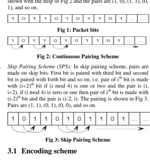
Our model is based on Pairing Scheme (PS). In PS technique the digital data is organized into grouping. The scheme divides the binary data stored in a packet into an equal size pairs and the size of each pair is two bits, i.e. 6 bit packet is divided into a group of three pairs and the size of each pair is two bit long. There are two types of PS that are used in our secure model. The pairing scheme includes:
A. Continuous Pairing Scheme (CPS): In continuous pairing scheme, pairs are made on continuous bits. First bit is paired with second bit and third bit is paired with forth bit and so on, i.e. pair of ith bit is made with (i+1)th bit if ith is the odd bit and the pair is (i, i+1). If ith bit is even bit, then pair of ith bit is
shown in Fig 1. Continuous Pairing of packet in Fig 1 is shown with the help of Fig 2 and the pairs are (1, 0), (1, 1), (0, 1), and so on.
Fig 1: Packet bits
Fig 2: Continuous Pairing Scheme
[image:3.595.42.282.86.343.2]B. Skip Pairing Scheme (SPS): In skip pairing scheme, pairs are made on skip bits. First bit is paired with third bit and second bit is paired with forth bit and so on, i.e. pair of ith bit is made with (i+2)th bit if (i mod 4) is one or two and the pair is (i, i+2), if (i mod 4) is zero or one then pair of ith bit is made with (i-2)th bit and the pair is (i-2, i). The pairing is shown in Fig 3. Pairs are (1, 1), (0, 1), (0, 0), and so on.
Fig 3: Skip Pairing Scheme
3.1
Encoding scheme
Due to the resource constraints sensor nodes, traditional expensive symmetric key cryptography algorithm is not a smart option. The selected scheme must be simple, yet efficient. In this section we discuss a very simple encoding scheme that can be used to ensure confidentiality of sensed data without increasing any kind of transmission overheads.
Each node chooses one of the eight specified encoding schemes, i.e. Scheme A to Scheme H. The encoding scheme is based on simple transposition and substitution techniques to achieve security at the node level. The scheme works on the pairing method that is applied on the digital data which is converted from analog signal to digital signal. These analog signals are generated on the basis of sensing the event in the environment. The encoding process works on digital data stored in the packet. The digital data stored into the packet is divided into pair of two bits, i.e. 6 bit packet is divided into a group of three pairs and the size of each pair is two bit long. There are eight encoding schemes, i.e. Scheme A to H. All the schemes are described below:-
A. Scheme A: First output bit is 0 if both pairing bits are same otherwise 1 and second output bit is same as given in the pairing bits.
Input bits Output bits
00 00
11 01
01 11
10 10
B. Scheme B: First output bit is 1 if both pairing bits are same otherwise 0 and second output bit is same as given in the pairing bits.
Input bits Output bits
00 10
11 11
01 01
10 00
C. Scheme C: First output bit is 0 if both pairing bits are same otherwise 1 and second output bit is the complement of second pairing bits.
Input bits Output bits
00 01
11 00
01 10
10 11
D. Scheme D: First output bit is 1 if both pairing bits are same otherwise 0 and second output bit is the complement of second pairing bits.
Input bits Output bits
00 11
11 10
01 00
10 01
E. Scheme E: First output bit is 0 if both pairing bits are same otherwise 1 and second output bit is same as second pairing bit if both pairing bits are same otherwise it is the complement of second pairing input bit.
Input bits Output bits
00 00
11 01
01 10
10 11
F. Scheme F: First output bit is 1 if both pairing bits are same otherwise 0 and second output bit is same as second pairing bit if both pairing bits are same otherwise it is the complement of second pairing input bit.
Input bits Output bits
00 10
11 11
01 00
10 01
G. Scheme G: First output bit is 0 if both pairing bits are same otherwise 1 and second output bit is complement of second pairing input bit if both input pairing bits are same otherwise it is same as second input pairing bit.
Input bits Output bits
00 01
11 00
01 11
10 10
Input bits Output bits
00 11
11 10
01 01
10 00
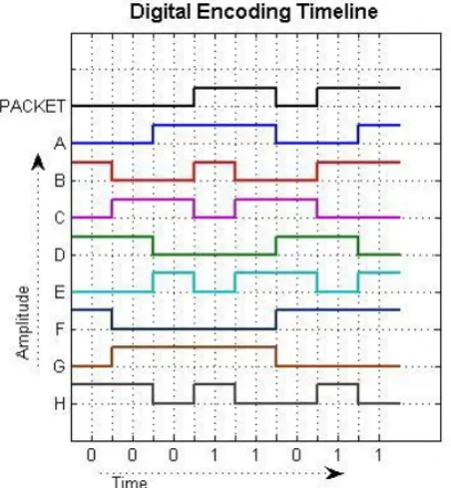
In the above specified eight encoding schemes, two input pairs are same as output pairs in Scheme A and B, i.e. in scheme A if the input pair is „0 0‟ or „1 0‟, the output pairing bits are same as input pair. Similarly in scheme B if the input pair is „1 1‟ or „0 1‟, the output pairing bits are same as input pair. On the other hand in scheme E, F, G and H only one output pair is same as input pair but in scheme C and D, all the output pairs are different from all the input pairs. In all the schemes output of every pair is independent of any other pair in any scheme. There are total 32 possible combinations make with the help of the entire encoding chart (four in each scheme out of eight schemes). Because only eight schemes are used so total three bits are enough to represent the encoding scheme selected by any sensor. All the encoding schemes are shown in Fig 4 where the digital data of the packet is „0 0 0 1 1 0 1 1‟ and CPS is used in all the schemes.
3.2
Relationship B/W Encoding Schemes
In the given timeline, it has been shown that scheme D is complement of scheme A and similarly scheme C is complement of scheme B. Relationship among all the schemes with other schemes are given below:-
A. Relation of Scheme A and Scheme B: Relationship between Scheme A and B is that 1st output pairing bit of Scheme B is complement of 1st output pairing bit of Scheme A, i.e. all the odd output pairing bits of Scheme B are complement of all odd output pairing bits of Scheme A and rest of the even output pairing bits in both the schemes are same.
B. Relation of Scheme A and Scheme C: Relationship between Scheme A and C is that 2nd output pairing bit of Scheme C is complement of 2nd output pairing bit of Scheme A, i.e. all the even output pairing bits of Scheme C are complement of all even output pairing bits of Scheme A and rest of the odd output pairing bits in both the schemes are same.
C. Relation of Scheme A and Scheme D: Relationship between Scheme A and Scheme D is that in Scheme D all the output pairing bits are complement of all the output pairing bits in Scheme A, i.e. Scheme D is complement of Scheme A.
[image:4.595.316.520.74.295.2]D. Relation of Scheme A and Scheme E: Relationship between Scheme A and E is that all the odd bits in both the scheme are same whereas even output pairing bits in Scheme E is complement of even output pairing bit of Scheme A if the proceeding odd output pairing bit is 0 in any of the scheme otherwise this bit is same in both the schemes.
Fig 4: Relationship between Encoding Schemes
E. Relation of Scheme A and Scheme F: Relationship between Scheme A and F is that all the odd output pairing bits in Scheme F are complement to all the odd output pairing bit of Scheme A whereas even output pairing bits in Scheme F is complement of even output pairing bit of Scheme A if the proceeding odd output pairing bit is 0 in any of the scheme otherwise this bit is same in both the schemes.
F. Relation of Scheme A and Scheme G: Relationship between Scheme A and G is that all the odd output pairing bits in both the Schemes are same whereas the even output pairing bits in Scheme G are complement of even output pairing bits in Scheme A if the proceeding odd output pairing bit is 1 in any of the scheme otherwise this bit is same in both the schemes.
G. Relation of Scheme A and Scheme H: Relationship between Scheme A and H is that all the odd output pairing bits in Scheme H are complement to all the odd output pairing bits in Scheme A whereas even output pairing bits in Scheme H is complement of even output pairing bit of Scheme A if the proceeding odd output pairing bit is 1 in scheme A otherwise this bit is same in both the schemes.
H. Relation of Scheme B and Scheme C: Relationship between Scheme B and Scheme C is that in Scheme C all the output pairing bits are complement of all the output pairing bits in Scheme B, i.e. Scheme C is complement of Scheme B.
I. Relation of Scheme B and Scheme D: Relationship between Scheme B and D is that 2nd output pairing bit of Scheme D is complement of 2nd output pairing bit of Scheme B, i.e. all the even output pairing bits of Scheme D are complement of all even output pairing bits of Scheme B and rest of the odd output pairing bits in both the schemes are same.
J. Relation of Scheme B and Scheme E: Relationship between Scheme B and E is that all the odd output pairing bits in Scheme E are complement to all the odd output pairing bits in Scheme B whereas even output pairing bits in Scheme E is complement of even output pairing bit of Scheme B if the proceeding odd output pairing bit is 1 in scheme B otherwise this bit is same in both the schemes.
the Schemes are same whereas the even output pairing bits in Scheme F are complement of even output pairing bits in Scheme B if the proceeding odd output pairing bit is 1 in any of the scheme otherwise this bit is same in both the schemes.
L. Relation of Scheme B and Scheme G: Relationship between Scheme B and G is that all the odd output pairing bits in Scheme G are complement to all the odd output pairing bit of Scheme B whereas even output pairing bits in Scheme G is complement of even output pairing bit of Scheme B if the proceeding odd output pairing bit is 0 in any of the scheme otherwise this bit is same in both the schemes.
M. Relation of Scheme B and Scheme H: Relationship between Scheme B and H is that all the odd bits in both the scheme are same whereas even output pairing bits in Scheme H is complement of even output pairing bit of Scheme B if the proceeding odd output pairing bit is 0 in any of the scheme otherwise this bit is same in both the schemes.
N. Relation of Scheme C and Scheme D: Relationship between Scheme C and D is that 1st output pairing bit of Scheme D is complement of 1st output pairing bit of Scheme C, i.e. all the odd output pairing bits of Scheme D are complement of all odd output pairing bits of Scheme C and rest of the even output pairing bits in both the schemes are same.
O. Relation of Scheme C and Scheme E: Relationship between Scheme C and E is that all the odd output pairing bits in both the Schemes are same whereas the even output pairing bits in Scheme E are complement of even output pairing bits in Scheme C if the proceeding odd output pairing bit is 1 in any of the scheme otherwise this bit is same in both the schemes.
P. Relation of Scheme C and Scheme F: Relationship between Scheme C and F is that all the odd output pairing bits in Scheme F are complement to all the odd output pairing bits in Scheme C whereas even output pairing bits in Scheme F is complement of even output pairing bit of Scheme C if the proceeding odd output pairing bit is 1 in scheme C otherwise this bit is same in both the schemes.
Q. Relation of Scheme C and Scheme G: Relationship between Scheme C and G is that all the odd bits in both the scheme are same whereas even output pairing bits in Scheme G is complement of even output pairing bit of Scheme C if the proceeding odd output pairing bit is 0 in any of the scheme otherwise this bit is same in both the schemes.
R. Relation of Scheme C and Scheme H: Relationship between Scheme C and H is that all the odd output pairing bits in Scheme H are complement to all the odd output pairing bit of Scheme C whereas even output pairing bits in Scheme H is complement of even output pairing bit of Scheme C if the proceeding odd output pairing bit is 0 in any of the scheme otherwise this bit is same in both the schemes.
S. Relation of Scheme D and Scheme E: Relationship between Scheme D and E is that all the odd output pairing bits in Scheme E are complement to all the odd output pairing bit of Scheme D whereas even output pairing bits in Scheme E is complement of even output pairing bit of Scheme D if the proceeding odd output pairing bit is 0 in any of the scheme otherwise this bit is same in both the schemes.
T. Relation of Scheme D and Scheme F: Relationship between Scheme D and F is that all the odd bits in both the scheme are same whereas even output pairing bits in Scheme F is complement of even output pairing bit of Scheme D if the proceeding odd output pairing bit is 0 in any of the scheme otherwise this bit is same in both the schemes.
U. Relation of Scheme D and Scheme G: Relationship between Scheme D and G is that all the odd output pairing bits in Scheme G are complement to all the odd output pairing bits in Scheme D whereas even output pairing bits in Scheme G is complement of even output pairing bit of Scheme D if the proceeding odd output pairing bit is 1 in scheme D otherwise this bit is same in both the schemes.
V. Relation of Scheme D and Scheme H: Relationship between Scheme D and H is that all the odd output pairing bits in both the Schemes are same whereas the even output pairing bits in Scheme H are complement of even output pairing bits in Scheme D if the proceeding odd output pairing bit is 1 in any of the scheme otherwise this bit is same in both the schemes.
W. Relation of Scheme E and Scheme F: Relationship between Scheme E and F is that 1st output pairing bit of Scheme F is complement of 1st output pairing bit of Scheme E, i.e. all the odd output pairing bits of Scheme F are complement of all odd output pairing bits of Scheme E and rest of the even output pairing bits in both the schemes are same.
X. Relation of Scheme E and Scheme G: Relationship between Scheme E and G is that 2nd output pairing bit of Scheme G is complement of 2nd output pairing bit of Scheme E, i.e. all the even output pairing bits of Scheme G are complement of all even output pairing bits of Scheme E and rest of the odd output pairing bits in both the schemes are same.
Y. Relation of Scheme E and Scheme H: Relationship between Scheme E and Scheme H is that in Scheme H all the output pairing bits are complement of all the output pairing bits in Scheme E, i.e. Scheme H is complement of Scheme E.
Z. Relation of Scheme F and Scheme G: Relationship between Scheme F and Scheme G is that in Scheme G all the output pairing bits are complement of all the output pairing bits in Scheme F, i.e. Scheme G is complement of Scheme F.
AA.Relation of Scheme F and Scheme H: Relationship between Scheme F and H is that 2nd output pairing bit of Scheme H is complement of 2nd output pairing bit of Scheme F, i.e. all the even output pairing bits of Scheme H are complement of all even output pairing bits of Scheme A and rest of the odd output pairing bits in both the schemes are same.
BB. Relation of Scheme G and Scheme H: Relationship between Scheme G and H is that 1st output pairing bit of Scheme H is complement of 1st output pairing bit of Scheme G, i.e. all the odd output pairing bits of Scheme H are complement of all odd output pairing bits of Scheme G and rest of the even output pairing bits in both the schemes are same.
4.
Simulation Environment
To understand the behavior of the encoding scheme, we conducted an extensive study to evaluate its effect on wireless sensor networks in terms of neighbor‟s connectivity. In our experiments, we consider a two dimensional coverage area „A‟ that is 100 meter square. This network consists of a set of sensor nodes S = {s1, s2,…,sn). Each sensor Si, i=1..n located
at random coordinate (xi,yi) inside „A‟. Each sensor has a
sensing range of ri, i.e. 15 meters. We then calculate the
results on connectivity when a random encoding scheme is provided to each sensor. The number of encoding scheme in each sensor is increased from single scheme to eight schemes.
5.
Result and Discussions
sensor network has at least eight neighbors and thereby each sensor will be physically connected in the network when it has more than 8 neighbors. A sensor node is assumed to be logically connected in the network if and only if it is physically connected in the network and all its encoding schemes are matched with its neighbors too. The number of encoding schemes in each sensor is variable from single scheme to eight schemes for measuring the behavior neighbors in the network. Figure 4 shows that more than 200 sensors are required to achieve more than 90 percent physical connectivity. Fig 5 shows the behavior of the network for physical connectivity when more than eight neighbors are available for each sensor. The number of physical neighbors is shown in Fig 6. Fig 7 shows the logical connectivity for each encoding schemes. When we apply only one encoding scheme, the percentage of sensors with more than eight logical neighbors is approximately twenty percentage but when we apply all the eight encoding schemes then this percentage is same as in case of physical connectivity. The number of logical neighbors is shown in Fig 8. Table 1 shows the key size and block size used by different symmetric key cryptography algorithms where the size of key is very large in comparison with proposed scheme „PBES‟. The block size in all the algorithms is generally fixed and very large which is not the required in case where packet size is assumed to be very small. In proposed PBES scheme the key size is of 3 bit wide to differentiate all 8 encoding schemes. We can encode any size packet by stream cipher method where no additional memory is required to store the result of intermediate step to start the next step. Proposed scheme is capable to encode any variable size packet as output results are produced as a sequence of bits and decision is taken for a portion of processed input received so far.
Table 1: Algorithms Settings
Algorithm
Key Size
(Bits)
Block Size
(Bits)
DES[15] 64 64
Triple DES[15] 192 64
AES[16] Variable (128,192 or
256) 128
Blowfish[17]
Variable (32-448)
Default (128)
64
RC2[18] Variable (8 to 128) 64
RC4[19] Variable (40 to 128) Variable (32, 64, 128)
RC6[20] Variable (128, 192 or
256 128
IDEA[21] 64 128
PBES 3 Variable
[image:6.595.319.529.76.445.2]Fig 5: Sensors Physical Connectivity
Fig 6: Sensors Physical Neighbors
Fig 7: Sensors Logical connectivity
[image:6.595.55.281.432.631.2]6.
Conclusions
In this paper, we proposed a security framework for WSNs by using multiple coding schemes exploring the simple logical operations. Simulation results indicates that proposed scheme is economical than the existing heavy cryptography algorithms such as DES, AES and IDEA or RSA in terms of reducing the resource requirements. In future, the performance of this model in terms of security can be increased by introducing the concept of proposed multiple encoding schemes in addition to light encryption algorithm.
7.
References
[1] Azeem, Md Abdul, Khaleel-ur-Rahman Khan and A. V. Pramod. "Security architecture framework and secure routing protocols in wireless sensor networks-survey." International Journal of Computer Science & Engineering Survey (IJCSES) Vol 2 (2011).
[2] Araujo, Alvaro, Javier Blesa, Elena Romero and Daniel Villanueva. "Security in cognitive wireless sensor networks. Challenges and open problems." EURASIP
Journal on Wireless Communications and
Networking 2012, no. 1 (2012): 1-8.
[3] Prasanna, S. and Srinivasa Rao. "An Overview of
Wireless Sensor Networks Applications and
Security." International Journal of Soft Computing and Engineering (IJSCE), ISSN: 2231-2307.
[4] Xiong, Xiaokang, Duncan S. Wong and Xiaotie Deng. "TinyPairing: a fast and lightweight pairing-based cryptographic library for wireless sensor networks." InWireless Communications and Networking Conference (WCNC), 2010 IEEE, pp. 1-6. IEEE, 2010
[5] Wander, Arvinderpal S., Nils Gura, Hans Eberle, Vipul Gupta and Sheueling Chang Shantz. "Energy analysis of public-key cryptography for wireless sensor networks." In Pervasive Computing and Communications, 2005. PerCom 2005. Third IEEE International Conference on, pp. 324-328. IEEE, 2005.
[6] Chan, Haowen, Adrian Perrig and Dawn Song. "Random key predistribution schemes for sensor networks." In Security and Privacy, 2003. Proceedings. 2003 Symposium on, pp. 197-213. IEEE, 2003.
[7] Eschenauer, Laurent and Virgil D. Gligor. "A key-management scheme for distributed sensor networks." In Proceedings of the 9th ACM conference on Computer and communications security, pp. 41-47. ACM, 2002
[8] Karlsson, Per, Lasse Oberg and Youzhi Xu. "An address coding scheme for wireless sensor networks." In Proceedings of the 5th Scandinavian Workshop on Wireless Ad-Hoc Networks (ADHOC‟05), pp. 3-4. 2005.
[9] Pfletschinger, Stephan, Monica Navarro and Christian Ibars. "Energy-efficient data collection in WSN with network coding." In GLOBECOM Workshops (GC Wkshps), 2011 IEEE, pp. 394-398. IEEE, 2011.
[10]Kolo, Jonathan Gana, S. Anandan Shanmugam, David Wee Gin Lim, Li-Minn Ang and Kah Phooi Seng. "An Adaptive Lossless Data Compression Scheme for Wireless Sensor Networks." Journal of Sensors 2012 (2012).
[11]Wang, Jin, Xiumin Wang, Shukui Zhang, Yanqin Zhu and Juncheng Jia. "An Efficient Reliable Communication Scheme in Wireless Sensor Networks Using Linear Network Coding." International Journal of Distributed Sensor Networks2012 (2012)
[12]Hu, Xiao-Min, Jun Zhang, Yan Yu, HS-H. Chung, Yuan-Long Li, Yu-Hui Shi and Xiao-Nan Luo. "Hybrid genetic algorithm using a forward encoding scheme for lifetime maximization of wireless sensor networks." Evolutionary Computation, IEEE Transactions on 14, no. 5 (2010): 766-781.
[13]Wang, Tsang-Yi, Yunghsiang S. Han, Biao Chen and Pramod K. Varshney. "A combined decision fusion and channel coding scheme for distributed fault-tolerant classification in wireless sensor networks." Wireless Communications, IEEE Transactions on 5, no. 7 (2006): 1695-1705.
[14]Ali, Nora, Hany ElSayed, Magdi El-Soudani and Hassanein Amer. "Single and Multi Coding Schemes for Efficient Wireless Sensor Networks." networks 2 (2012): 6.
[15]Standard, N. F. "Data Encryption Standard (DES)." Federal Information Processing Standards Publication (1999).
[16]Robertazzi, Thomas. "Advanced encryption standard (aes)." In Basics of Computer Networking, pp. 73-77. Springer New York, 2012.
[17]Verma, O. P., Ritu Agarwal, Dhiraj Dafouti and Shobha Tyagi. "Peformance analysis of data encryption algorithms." In Electronics Computer Technology (ICECT), 2011 3rd International Conference on, vol. 5, pp. 399-403. IEEE, 2011.
[18]W.Stallings, ''Cryptography and Network Security 4th Edition,'' Prentice Hall, 2005, PP. 58-309.
[19]Couture, Nathaniel and Kenneth B. Kent. "The effectiveness of brute force attacks on RC4." In Communication Networks and Services Research, 2004. Proceedings. Second Annual Conference on, pp. 333-336. IEEE, 2004.
[20]El-Fishawy, Nawal and OM Abu Zaid. "Quality of encryption measurement of bitmap images with RC6,
MRC6, and Rijndael block cipher
algorithms."International Journal of Network Security 5, no. 3 (2007): 241-251.