Optical Technique using Nano-spark Lightsource for Macro and Microscale
Image Acquisition to Study Diesel Spray Atomization
Azwan Sapit
1,a,
Mohd Azahari Razali
1,b,
M. Jaat
1,c,
Akmal Nizam Mohammad
1,d,
Amir Khalid
1,eand Bukhari Manshoor
1,f1Automotive Research Group, Faculty of Mechanical and Manufacturing Engineering, Universiti Tun Hussein Onn Malaysia, Parit Raja, 86400 Batu Pahat, Johor, Malaysia.
a[email protected], b[email protected], c[email protected], d[email protected], e[email protected], f[email protected]
Keywords: Diesel Spray, Atomization, Fuel Droplets, Optical Technique, Nano-spark Photography
Abstract. Atomization and fuel-air mixing is an important process in diesel combustion. It directly
affects the combustion and emission of diesel engine. Optical technique has the advantage of being unobtrusive in nature when compared to other technique. Nano-spark unit that has spark duration of 30ns was used as a lightsource to capture high resolution spray image using still film camera. The very short duration of the spark freeze the fast movement of the spray droplet, and sharp image of fuel droplet to be successfully captured by the camera, and then analyzed for sizing and spatial distribution. In addition, by using a more elaborate optical setup, dual image of the same spray can be captured, with a very short time interval between each of them. This provides the means to study dynamic behaviors of the diesel spray and also the droplets, as the progression of the spray and trajectory and velocity of the droplet can be analyze from these images.
Introduction
Many different techniques and instruments have been employed in the research upon spray and atomization to investigate spray characteristics, such as the sizes and velocities of droplets, and the spray patterns produced by different atomization devices. Generally, these techniques may be classified into three broad categories: mechanical, electrical and, and optical [1]. Though mechanical and electrical technique is applicable in measuring the spray droplet size and spray breakup length[2], it is intrusive in nature. Initial diesel spray study that measure droplet size[3] and breakup length[4] did use these two methods but proven to be very limited in measuring the temporal and spatial diesel spray evolution. Also the intrusive nature makes these techniques very difficult to apply for study under diesel engine like condition of high ambient pressure and high temperature.
As for optical technique, due to its non-intrusive nature, it is currently consider the most suitable technique for diesel spray study. Furthermore, it can be use to study the macroscopic and microscopic aspect of the spray, with good temporal and spatial resolution[5-7]. In particular, a variety of optical systems for spray analysis has been developed in recent years. Each system has its own advantages and limitations, but all benefit because of their non-intrusive natures. Some of these technique can be difficult to implement, need high level of operator skill to be successfully applied and also can be very expensive[1]. Examples of the mainly used optical techniques are direct visualization[8,9], Particle Image Velocimetry (PIV), Laser Beam Extinction (LBE), Laser Induced Fluorescence (LIF), Phase Doppler Particle Anemometer (PDPA).
Experiment Setup
Overview. Figure 1 shows the experimental setup of use in this study. It is composed of spray
chamber, rapid compression machine (RCM), fuel injection device and optical system paired with nano-spark lightsource. A rapid compression machine was used to create diesel atmosphere in the spray chamber. The spray chamber has two quartz windows in diameter of 60mm for the access of nano-spark light to a still camera. The spray chamber was filled with inert gas mixture of nitrogen and argon to prevent spray ignition. When ambient temperature reaches designated temperature after termination of rapid compression, fuel was injected into the spray chamber and spray behavior was taken by the optical system. All the images taken by films were scanned and changed to digital pictures. Fuels used was JIS#2 diesel fuel or also known as gas oil (GO). Fuels at room temperature were injected using a single-hole nozzle with hole-diameter of dn=0.18mm at an orientation angle of
15° from the injector centerline.
To obtain more detail information of fuel spray, magnification factor of 3.5 was applied throughout this experiment. Macro lens (PENTAX 135mm) was separately installed from camera body (Asahi Pentax 6x7) as shown in Fig.2 5. As a result, photography of spray was divided into three 15×20mm sections that were upstream, midstream and downstream of the spray as shown in Fig.3. A complete set of the three spray photos were combined to get a full figure of spray. Spray photos combination task was done precisely according to the scale of each part that was taken prior to the experiment. A spark head providing spark duration of 30ns was employed in order to capture fast moving images of droplets and to eliminate the blurring of subject[3-5]. Rapid spark duration at 30ns was needed in order to capture high quality of spray images which include detail images of flying fine droplets and vapor development. Photography was done inside a complete dark room and nano-spark at spark duration of 30ns performed as a backlight to the spray. Therefore, images acquired are the result of the attenuation of light emitted from nano spark source through the spray.
Nano-spark. The nano-spark photography unit was employed to capture the still image of the
evaporating sprays and droplets. As shown in Fig.2, this unit includes a nano second spark light sources known as spark-head. A capacitor with a capacity of 1400pF was installed inside the spark head. This capacitor was pulse-charged in about 60ns from the high voltage pulse generator switched by a thyratron. Automatic preionization of gas in the vicinity of the electrodes helps to create a highly reproducible instant gas breakdown. The time jitter is shorter than 60ns relative to the input trigger pulse. High-intensity light can be produced by electric discharge between electrodes located inside the spark head. The electrodes gap was fixed at 3mm and the supplied voltage was kept constant at 12kV, providing a spark duration of 30ns. Spray penetration speed generally exceeds 200m/s. However, the maximum droplets speed at the spray periphery was about 25m/s. Therefore, spark duration of 30ns is sufficient to capture the still images of the droplets.
Fig.1 Overview of spray observation and image capture system for nano-spark shadowgraph photography method (shown for single nano optical arrangement setup)
Fig.2 Cross section of the nano-spark lighsource unit head. Light are produce as a result from
Result and Discussion
Single Nano-spark Photography Optical Arrangement. Fig.4 shows the non-evaporating spray
image obtained by single nano-spark photography method. The dark area in the images corresponds to the location of the spray liquid phase, the droplets and the vapor phase. Experimental conditions were ambient temperature of Ti=298K and injection pressure of Pinj=40MPa. The significant feature
of this photograph is high resolution. Macroscopically, the high-density region can be observed along the spray axis from nozzle tip to the spray tip area. Simultaneously, many branch-like structures can be observed along the spray boundary from the midstream area to spray tip.
Left side figures show magnified images at spray boundary region (areas A and B). The images show droplets behavior at midstream and downstream of the spray. Inside every image, highly clear droplets images can be seen. Owing to these images, single spark method offers simultaneous measurement of macroscopic and microscopic parameters such as spray cone angle, spray penetration length, droplets diameter and droplets number at spray boundary region.
However, several important parameters to imagine droplets behavior such as droplets velocity, droplets flying direction, droplets size reduction rate or droplets evaporation rate cannot be obtained by single nano-spark photography method. To obtain these parameters, time depending variations of parameters should be measured. Thus, dual-nanospark photograph method is implemented to obtain the above mentioned parameters.
Dual Nano-spark Photography Optical Arrangement. To obtain the dynamic behavior of spray
droplet, and also study the progression of diesel spray, a new optical arrangement was developed. This method is named dual nano-spark shadowgraph, whereby two sets of spark head were used, which enables images to be captured at different timing into separate films without any interference from other optics.
Referring to Fig.5, this method employs two identical sets of optics including spark head, camera body, polarized filters and half mirrors. To perform the dual nano-spark photography method, two cameras with completely same specifications were used, Pentax 6x7 (medium format film camera) were steady fixed on a special bracket. Referring to the figure, optics 1 was installed along the single straight line. Meanwhile, optics 2 was installed along the C shape line at the center of experimental setup. As shown in the figure, spark light emerged from nano spark 1 illuminates spray at desired time after start of injection. As a result, first spray image will be captured on camera 1. Later, at a very short delay time interval, spark light from nano spark 2 illuminates spray and delayed spray image will be captured on camera 2.
During this process, both camera shutters were open simultaneously. To restrain images
Fig.3 Each spray will be capture at 3 different point of area and combine to make a full length
spray image. Fig.4 Single spark spray image (Ti=298K, Pinj=40MPa)
Droplet can be clearly seen at spray boundary. B
B
A
A
15mm
20m
illuminated by nano spark 1 to be captured on camera 2 or vice versa, four polarized filters (PL) were used in this experiment. Each filter was set in front of spark head 1, spark head 2, camera 1 and camera 2 respectively. Polarization angle of PL filter installed in optics 1 and optics 2 has difference of 90 degree from each other. Therefore, the PL filter in front of camera 2 could cut light beam emerged from spark head 1 and could allow light beam from spark head 2 to pass, or vice versa. As a result, only nano-spark 1 will be allowed to enter camera 1 and only nano-spark 2 will be allowed to enter camera 2. Polarization angle of optics 2 was adjusted to s-polarization angle to maximize the light intensity in optics 2. In addition to this, two half mirrors were set at 45 degree facing to spark head 2 and camera 2.
These half mirrors were used to put the part of optical passes in optics 1 and optics 2 on common axis in spray chamber and to divide them into camera 1 and camera 2. Although it is inevitable to have small angle difference of light beam axis between optics 1 and optics 2 passing through spray chamber, the two images of objects at focal point inside spray chamber were identical due to single lens(Nikkor) was used to process both images.
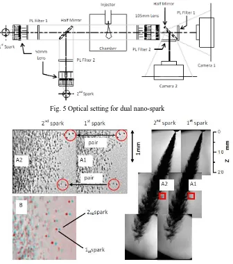
Images shown in Fig.6 shows set of spray images taken with dual nano-spark method. Fig.6 shows spray condition of low temperature Ti=298K, Pinj=40MPa, t=0.5ms. Spark interval between
nano-spark 1 and nano-spark 2 was set at Δt=15µs. As seen in the figure, two consecutive images from one single shot of spray at specific short time interval can be obtained.
[image:4.595.143.479.385.766.2]Referring to Fig.2 18, magnified images of A1 and A2 show a lot of clear droplets. Cross visual reference between detailed images from the A1 (1st spark) and A2 (2nd spark) enabled many pairs of droplets to be detected. Using this method, droplets pairing process could be done not only at low droplets number-density region but also at high droplets number-density region.
Fig. 5 Optical setting for dual nano-spark shadowgraph photography method
Meanwhile, image B show overlapped spray images of A1 (1st spark) and A2 (2nd spark). In this image, droplets exposed by 1st spark at inner side while its pair of 2nd spark at outer part of the spray. Clearly, at adequate time interval, many pair of droplets can be seen. These pair of droplets can be detected not only at spray boundary area but also inside high droplets density region. Using this method, flying droplets can still be seen clearly even at spray tip region. By applying dual nano-spark method, it can offer information on droplets behavior such as droplets velocity, flying direction and droplets size reduction rate inside spray boundary region and spray tip region.
Summary
Although there are many optical techniques to study diesel engine spray, most of them produce macroscopic image of the spray. With the proposed optical technique and optical arrangement, microscopic detail of the diesel engine spray can be captured. Critical data such as droplet sizing can be extracted from this high resolution image. Furthermore, by introducing a more sophisticated optical arrangement coined dual-nano spark photography method, the droplet dynamic behaviors such as flying angle and velocity can be study.
Acknowledgement
The authors also would like to thank the Ministry of Higher Education Malaysia for supporting this research under the Exploratory Research Grant Scheme (ERGS) vot.E032.
Reference
[1] S. N. Soid and Z. a. Zainal, “Spray and combustion characterization for internal combustion engines using optical measuring techniques – A review,” Energy, vol. 36, no. 2, pp. 724–741, Feb. 2011.
[2] Hiro Hiroyasu and Masataka Arai, “Structures of Fuel Sprays in Diesel Engines,” SAE Paper, 900475, 1990.
[3] Hiroyuki Hiroyasu and Toshikazu Kadota, “Fuel Droplet Size Distribution in Diesel Combustion Chamber,” Bulletin of JSME, vol. 19, no. 135, pp. 1064–1072, 1976.
[4] Masanori Shimizu, Masataka Arai, and Hiroyuki Hiroyasu, “Measurement of Breakup Length in High Speed Jet ,” Bulletin of JSME, vol. 27, no. 230, pp. 1709–1715, 1984.
[5] Koch, Schmid, and Leipertz, “Influence Of Injection Nozzle Parameters On The Spray Propagation And Combustion In A Di-Diesel-Engine,” ICLASS 2006, Kyoto, Japan, 2006.
[6] H. Gen Fujimoto, H. Adachi, T. Yano, N. Marubayashi, T. Hori, and J. Senda, “Spatial Droplets Size Distribution in a Diesel Spray Taken by Photography with Super High Resolution,” ILASS – Europe 2010, 23rd Annual Conference on Liquid Atomization and Spray Systems, Brno, Czech Republic, September 2010, 2010.
[7] A. Sapit, S. Nagayasu, Y. Tsuboi, Y. Nada, and Y. Kidoguchi, “A Study on Improvement of Diesel Spray Characteristics Fueled by Rape-seed Oil”, SAE Paper, 2011-32-0561, 2011.
[8] Marie Bysveen, Terje Almas, Kjell Arne Ulvund, Atle Jorgensen, and Frode Kvinge, “Development of a Shadowgraph Image Technique Describing the Fuel Spray Behavior in a Rapid Compression Machine,” SAE Paper, 2004-01-2934, 2004.