International Journal of Emerging Technology and Advanced Engineering
Website: www.ijetae.com (ISSN 2250-2459, ISO 9001:2008 Certified Journal, Volume 3, Issue 7, July 2013)
37
Power Loss Reduction in the Active Distribution Network by
Doubly Fed Induction Generator (DFIG) Placement and Sizing
Using Ordinary Particle Swarm Optimization (PSO) and an
hybrid of Genetic Algorithm (GA) and PSO (HGAPSO).
Peter Musau Moses
1, Dr. Nicodemus Abungu Odero
2, Prof. J. Mwangi Mbuthia
31Post Graduate Student, 2Senior Lecturer, 3Associate Professor, Department of Electrical and Information Engineering, The University of Nairobi-Kenya , P.O Box 30197-00100 GPO
Abstract-- Due to the increased importance of DFIGs in optimization of real and reactive power losses and the maintenance of voltage profile, the general methods of DG placement and sizing in the existing literature cannot be of practical importance in DFIG .In this paper a pure PSO method used in general DG is compared with a HGAPSO in the siting and sizing of DFIG with the objective of minimizing power losses .The corresponding Combined participation factors are assigned using the DFIG Domain Distributed Slack Bus Model and a comparison made on the two schemes of loss minimization. The obtained results for the real and reactive power losses and voltage voltage profile illustrate the DFIG need in the modern power system.
Keywords-- Distributed Generator (DG), Doubly Fed
Induction generator (DFIG), Hybrid GAPSO
(HGAPSO),Genetic Algorithm(GA), Particle Swarm
Optimisation(PSO).
I. INTRODUCTION
The electric distribution system is the most extensive part of the electrical system, and consequently, it is the mainly responsible for energy losses [1]. Therefore the use of optimization techniques in the design of this subsystem can lead to significant economic gains, obtaining networks which minimize the immediate costs (those related to installation and reconductoring) and further costs (costs related to energy losses and system maintenance) [2–4] It is well known that distribution systems are in constant evolution, subject to load increasing in different places at different times, which leads to the need of successive system expansions [5, 7, 8].
Since the last few years, the interest in the placement of DG in utility network has increased due to its effective role in reducing the power loss of the distribution networks so as to serve remote loads.
In recent years, the power industry has experienced significant changes on the distribution power system primarily due to the implementation of smart-grid technology and the incremental implementation of distributed generation. Distributed Generation (DG) is simply defined as the decentralization of power plants by placing smaller generating units closer to the point of consumption, traditionally ten mega-watts or smaller. While DG is not a new concept, DG is gaining widespread interest primarily due to increase in customer demand, advancements in technology, economics, deregulation, environmental and national security concerns.
The distribution power system traditionally has been designed for radial power flow, but with the introduction of DG, the power flow becomes bidirectional. As a result, conventional load flow analysis tools and techniques are not able to properly assess the impact of DG on the electrical system. The presence of DG on the distribution system creates an array of potential problems related to safety, stability, reliability and security of the electrical system. Distributed generation on a power system affects the voltages, power flow, short circuit currents, losses and other power system analysis results. Whether the impact of the DG is positive or negative on the system will depend on the location and size of the DG.This paper will go very specific to study the placement and sizing of the DFIG.
International Journal of Emerging Technology and Advanced Engineering
Website: www.ijetae.com (ISSN 2250-2459, ISO 9001:2008 Certified Journal, Volume 3, Issue 7, July 2013)
38
To overcome these problems, solution methodologies and techniques are suggested by various authors to solve the problem of optimal allocation of DGs in the utility network. The exact allocation of DGs is achieved by considering all feasible combinations of sites and sizes of DGs in the system. The number of alternatives could however, be very large as the number of variables of the problem (i.e. number of DGs and number of nodes of the system) increases.
A: General DG placement and sizing methods:A review
Distributed generation utilization is an effective alternative for reducing this cost by generation near the load points.In recent years, several studies have considered techniques for locating DG units on distribution systems.
Rau and Wan [22] have used gradient and second order method to minimize loss ,line loading and reactive power requirements in the Distribution network .Willis [23] investigated loss minimization using analytical based 2/3 rule ,assuming a constant power source and a uniformly distributed load.Hybrid and Constraint Based Multi Objective Programming(HCBMOP) and GA method was proposed by Celli et al[24] to minimize the cost of network upgrading ,power losses and energy required by customer.He later used the method to minimize the cost of network upgrading ,cost of energy losses and DG network acceptability index[25] with the
DG fully considered as a valid planning
alternative.Carpinelli et al [25] used the method proposed in [24] for a peak load with constant growth rate and a constant power source to minimize the cost of losses and to improve voltage quality and harmonic distortions.Kamalnia et al[26] used GA and Multiple Attribute Making Decision (MAMD) approach on a PQ model DG to investigate its technical attributes such as reactive power flows, voltage variation and active loss as well as the economic attributes which include line congestion ,capital cost and emission.
El-khattam et al[27] used an Heuristic Iterative Search method to minimize the cost of investment and operation of DGs,loss and energy required by customers;which Satish et al [28] later applied to minimize DG investment and operation losses and energy purchased from the main grid.
Falaghi and Haghifam[29] use Anti- Colony Optimization(ACO) on a time varying load to minimize investment cost ,operation cost and energy buying from transmission grid. Further Soroudi and Ehsan [30] used Particle Swarm Optimization on a multi- load level to minimize the cost of active losses,investment and operation cost of DG and emission cost.
The other methods used include analytical approach[28],simulated annealing[31,32,58],optimal power flow[33],sensitivity analysis[34], fast sequential quadratic programming [35] and NSGA II and max-min approach [36].All these methods have not take care of the intermittent renewables and therefore in practice they are inaccurate.
GA with decision making approach is used by Carpinelli et al[37] to minimize the cost of power losses and network upgrading for a wind generator with a peak load and constant load growth.Ochoa el al[38] used multi objective optimization with NSGA for a wind generator with a time varying load to maximize the intergration of DG and energy export ;minimizing losses and short circuit level
Several analytical approaches were also proposed in the literature [39-43]. GA based methods and PSO technique was also presented [44,45,48 ]. EP based method and FL based method are also presented in [49] and [50]. The other methods like probabilistic based MINLP [59], probabilistic based MC simulation [60], ABC [42], DLF [61], and OPF [51, 52, 53] are also presented by various authors. The hybrid based methods, like GA-PSO, GA-TS, and Fuzzy-GA are suggested by [54-56], respectively.
B:DFIGplacement and sizing importance
Distributed generation has been growing rapidly in power systems. Studies by the Electric Power Research Institute(EPRI) and the Natural Gas Foundation indicate that 60% or higher of new generation will be distributed generation by 2030 with 30% being wind based using the commercially viable DFIG [11,12], hence such wind based distributed generation will play an important role in power systems.
International Journal of Emerging Technology and Advanced Engineering
Website: www.ijetae.com (ISSN 2250-2459, ISO 9001:2008 Certified Journal, Volume 3, Issue 7, July 2013)
39 C: Objective
The main objective of this paper is to use HGAPSO in the placement and sizing of the DFIG with the aim of reducing real and reactive power losses. The results will be compared with those of ordinary PSO and the combined participation factors assigned to the various buses using DFIG domain Distributed slack bus model
II. DFIGPLACEMENT AND SIZING USING HGAPSO
A: The need for HGAPSO Particle Swarm Optimization
Swarm Intelligence (SI) is an innovative distributed intelligent paradigm for solving optimization problems that originally took its inspiration from the biological examples by swarming, flocking and herding phenomena in
vertebrates. Particle Swarm Optimization (PSO)
incorporates swarming behaviors observed in flocks of birds, schools of fish, or swarms of bees, and even human social behavior, from which the idea is emerged [13,14,15]. PSO is a population-based optimization tool, which could be implemented and applied easily to solve various function optimization problems. As an algorithm, the main strength of PSO is its fast convergence, which compares favorably with many global optimization algorithms like Genetic Algorithms (GA)[16] Simulated Annealing (SA)[17,18] and other global optimization algorithms. For applying PSO successfully, one of the key issues is finding how to map the problem solution into the PSO particle, which directly affects its feasibility and performance.
Genetic Algorithm
Genetic Algorithms are a family of computational models inspired by evolution.These algorithms encode a potential solution to a specific problem on a simple chromosome-like data structure and apply recombination and mutation operators to these structures so as to preserve critical information. An implementation of a genetic algorithm begins with a population of (usually random) chromosomes.One then evaluates these structures and allocates reproductive opportunities in such a way that those chromosomes which represent a better solution to the target problem are given more chances to reproduce than those chromosomes which are poorer solutions. This is
called survival for the fittest.The goodness of a solution is
typically defined with respect to the current population. The genetic algorithm can be viewed as two stage process. It starts with the current population. Selection is applied to the current population to create an intermediate population.
Then recombination and mutation are applied to the intermediate population to create the next population. The process of going from the current population to the next population constitutes one generation in the execution construction of the intermediate population is complete and recombination can occur. This can be viewed as creating the next population from the intermediate population. Crossover is applied to randomly paired strings with a probability denoted Pc. A pair of strings is picked with probability Pc for recombination. These strings form two new strings that are inserted into the next population. After recombination, mutation operator is applied. For each bit in the population, is mutated with some low probability Pm. Typically the mutation rate is applied with less than 1% probability. In some cases mutation is interpreted as randomly generating a new bit in which case, only 50% of the time will the mutation actually change the bit value. After the process of selection, recombination and mutation, the next population can be evaluated. The process of evaluation, selection, recombination and mutation forms one generation in the execution of a genetic algorithm. In this paper, the mutation genetic operator is used to introduce divergence to the PSO so as to escape the local maxima.
Hybrid PSO with GA(HGAPSO)
The drawback of PSO is that the swarm may prematurely converge. The underlying principle behind this problem is that, for the global best PSO, particles converge to a single point, which is on the line between the global best and the personal best positions. This point is not guaranteed for a local optimum[19] .Another reason for this problem is the fast rate of information flow between particles, resulting in the creation of similar particles with a loss in diversity that increases the possibility of being trapped in local optima.A further drawback is that
stochastic approaches have problem-dependent
International Journal of Emerging Technology and Advanced Engineering
Website: www.ijetae.com (ISSN 2250-2459, ISO 9001:2008 Certified Journal, Volume 3, Issue 7, July 2013)
40
Therefore, from the above, it can be concluded that the PSO performance is dependent. The problem-dependent performance can be addressed through hybrid mechanism. It combines different approaches to be benefited from the advantages of each approach.
To overcome the limitations of PSO, hybrid algorithms with GA are proposed. The basis behind this is that such a hybrid approach is expected to have merits of PSO with those of GA. One advantage of PSO over GA is its algorithmic simplicity. Another clear difference between PSO and GA is the ability to control convergence. Crossover and mutation rates can subtly affect the convergence of GA, but these cannot be analogous to the level of control achieved through manipulating of the inertia weight. In fact, the decrease of inertia weight dramatically increases the swarm‟s convergence. The main problem with PSO is that it prematurely converges [19] to stable point, which is not necessarily maximum. To prevent the occurrence, position update of the global best particles is changed. The position update is done through some hybrid mechanism of GA. The idea behind GA is due to its genetic operators crossover and mutation. By applying crossover operation, information can be swapped between two particles to have the ability to fly to the new search area. The purpose of applying mutation to PSO is to increase the diversity of the population and the ability to have the PSO to avoid the local maxima.
There are three different hybrid approaches are proposed [19]. In PSO-GA (Type 1) ,the gbest particle position does not change its position over some designated time steps, the crossover operation is performed on gbest particle with chromosome of GA. In this model both PSO and GA are run in parallel.In PSO-GA (Type 2) ,the stagnated pbest particles are change their positions by mutation operator of GA. Lastly,in PSO-GA (Type 3), the initial population of PSO is assigned by solution of GA. The total numbers of iterations are equally shared by GA and PSO. First half of the iterations are run by GA and the solutions are given as initial population of PSO. Remaining iterations are run by PSO.In this paper,the PSO-GA type 2 is preferred since we are interested in changing the siting of the DFIGs optimize the power losses ,taking their capacities as a constant..The cross over genetic operator is not of any importance in this paper since the DFIGs are independent of each other hence PSO-GA Type 1 and Type 3 cannot be used.
PSO, which is stochastic in nature and makes use of the memory of each particles as well as the knowledge gained by the swarm as a whole, has been proved to be powerful in solving many optimization problems.
The hybrid PSO systems find a better solution without trapping in local maximum, and to achieve faster convergence rate. This is because when the PSO particles stagnate, GA diversifies the particle position even though the solution is worse. In PSO-GA, particle movement uses randomness in its search. Hence, it is a kind of stochastic optimization algorithm that can search a complicated and uncertain area. This makes PSO-GA more flexible and robust. Unlike standard PSO, PSO-GA is more reliable in
giving better quality solutions with reasonable
computational time, since the hybrid strategy avoids premature convergence of the search process to local optima and provides better exploration of the search process.
B: The DFIG capability limit curve curves
The model of a DFIG used in this paper consists of a pitch controlled wind turbine and an induction generator[20,21].The stator of the DFIG is directly connected to the grid ,while the rotor is connected to the converter consisting of two back to back pulse width modulated (PWM)inveters,which allow direct control of the rotor currents.
Direct control of the rotor currents allows for the variable speed operation and reactive power control thus the DFIG can operate at a higher efficiency over a wide range of wind speeds and thus help in providing voltage support for the power grid.The characteristics make the DFIG ideal for use as a wind generator,whose equivalent
[image:4.612.332.589.484.627.2]circuit is as shown in the figure 1.0.
Fig 1:Equivalent circuit of a DFIG [20,21]
The stator active and reactive power can be expressed in terms of the stator and rotor currents as [20,21]
)
1
...(
...
...
...
)
3
(
22 2
I
V
Q
International Journal of Emerging Technology and Advanced Engineering
Website: www.ijetae.com (ISSN 2250-2459, ISO 9001:2008 Certified Journal, Volume 3, Issue 7, July 2013)
41
In the PQ plane,the equation (1) represents the circumference centered at the origin [0,0] with the radius equal to the stator speed apparent power.Equation (2)
represents a circumference centered at and
radius equal to .Therefore given the
maximim rotor and stator allowable currents limits
, the DFIG capability limits can be
obtained.The composed DFIG capability limits curve is
shown in Figure 2.0 where Taking
the steady state stability of the DFIG into account,represented by the vertical line at the
cordinate,it is obvious that the DFIGreal and reactive power capability mainly depends on the maximum allowable roror current.
From the Figure,the DFIG can operate at any point in the intersecting area within the given limits.when the available active power is far from its maximum,the amount of reactive power is high.The large reactive power control capability of the DFIG make it possible to use DFIG as the continuous reactive power support to support system
[image:5.612.74.270.454.658.2]voltage control.
Fig 2:DFIG Capability Limits Curve[20]
C: Problem formulation
The real power loss in the distribution system is very significant from the system operation point of view. The difference between the generated power and the power demand gives the power loss .That is :
The objective of the placement technique is to minimize the total real power loss. Mathematically, the objective function can be written as:
Where
is the real power participation factor,
is the reactive power participation factor
,and are the net real and reactive power
injections in bus “ i” and “j” respectively
is the resistance between bus “ i” and “j” ,
and are the voltage and angle at bus “ i” and
“j” respectively.
In the objective function,the network parameters are absorbed in the loss equation by the real and reactive participation factors formulated in [46]
) 2 ( ... 2
)
3
(
)
3
(
2 2 2I
V
X
X
X
V
Q
P
s rs m
s s s
s
International Journal of Emerging Technology and Advanced Engineering
Website: www.ijetae.com (ISSN 2250-2459, ISO 9001:2008 Certified Journal, Volume 3, Issue 7, July 2013)
42
The objective function is solved subject to the following constraint of DFIG domains and the power distribution system parameters:
(i)Power balance
(ii) DFIG active capability limits
(iii) DFIG reactive capability limits
(v) Voltage constraints at the buses
(vi) Line thermal limit
D: HGAPSO based optimization algorithm
The HGAPSO based approach for solving the optimal sizuing and placement of the DFIG is aimed at minimizing the distribution line real and reactive losses.In this paper,the reactive power output is obtained by means of the DFIG power curves after the active power output is known.The total active power output is obtained by the equation(5).Considering the capability limits of the DFIGs,the maximum of the reactive power that each DFIG can generate or absorb,the HGAPSO based approach for solving the problem to minimizes the losses takes the following steps.
Step 1:Input the line and bus data and the bus voltage limit
Step 2:calculate the loss using distribution load flow based on backward forward sweep
Step 3:Randomly generate an initial population (array ) of particl;es with random initial positions and velocities on dimensions in the solution space.set the iteration counter
Step 4:For each particle,if the bus voltage is within the limits,perform mutation on the particle position ,one by one ,keeping the velocity fixed,then perform mutation on the velocity ,keeping the position fixed.Other n positions and k velocities are obtained.Calculate the total losses as in equation 1 in each case.
Step 5:For each particle,compare its objective position and
velocity with the individual best .If the objective value is
lower than Pbest ,set this value as the current Pbest,and
record the corresponding particle position.
Step 6:Compare all components of the particle according to their fitness values.Choose the particle associated with the
minimum individual best Pbest of all the particles and set
the value of this Pbest as the current overall best Gbest
Step 7:If the iteration number reaches the maximum
limit,go to step 9.otherwise set iteration index
and go back to step 4
Step 8:Update the velocity and position of the particle
Step 9:If the particle equals to the population size N,print
out the optimal solution of the targeted problem,otherwise
set the particle to i=1 and go to step 3
Step 10.Assign Combined participation Factors to each particle taking into consideration the DFIG domains[46]
)
5
...(
...
...
1
1
P
P
L n
i Di n
i
P
DGi
)
6
.(
...
...
max max
P
P
P
DGi
DG
DGi) 11 ...( ... max
P
P
ij ij)
10
..(
...
...
...
max min
International Journal of Emerging Technology and Advanced Engineering
Website: www.ijetae.com (ISSN 2250-2459, ISO 9001:2008 Certified Journal, Volume 3, Issue 7, July 2013)
43
The best position includes the optimal locations and sizes of the DFIGs and the corresponding fitness value represents the minimum total real power loss.
E: 33 bus radial distribution test system .
IEEE recommended balanced distribution systems include the radial 16 Bus,30 Bus ,33 Bus 94 Bus 69 Bus and 119 Bus systems[57],with the 33 Bus and the 69 Bus being commonly for most simulations used because they are balanced topologies.
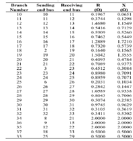
[image:7.612.333.548.160.389.2]In this paper, the distribution test systems used is the radial 33 bus systems. The system has 32 sectionalizing branches,5 tie switches , nominal voltage of 12.66KV and a total system load 3.72 MW and 2.3 MVAR. The original total real power loss and reactive power loss in the system are 221.4346 Kw( 5.95%) and 150.1784 kVAR( 6.53% ).The network diagram is as shown in figure 1
Figure 3:IEEE 33 Bus Radial Distribution System TABLE I
IEEE 33 BUS RADIAL SYSTEM LOAD DATA
TABLE II
IEEE 33 BUS RADIAL SYSTEM BUS DATA
F: Results and analyis
Simulations were run on the 33Bus Radial distribution Test System.The real and reactive power losses obtained through load flow,PSO and HGAPSO are as shown in the tables III,IV,V,and VI
TABLE III
CASE A:1.5 MW DFIG ON BUS 18
METHOD P LOSS
KW
QLOSS
KVAR
LOSS REDUCTION %
LOAD FLOW
221.4346 150.1784 REAL REACTIVE
PSO 70.9526 57.2155 67.95 61.90
[image:7.612.94.226.332.507.2]International Journal of Emerging Technology and Advanced Engineering
Website: www.ijetae.com (ISSN 2250-2459, ISO 9001:2008 Certified Journal, Volume 3, Issue 7, July 2013)
[image:8.612.43.299.109.701.2]44
TABLE IV
CASE B:1.5 MW DFIG ON BUS 8
METHOD P LOSS
KW
QLOSS
KVAR
LOSS REDUCTION %
LOAD FLOW
221.4346 150.1784 REAL REACTIVE
PSO 69.9526 56.3189 68.41 62.50
PSO-GA 68.4589 54.9676 69.09 63.40
TABLE V
CASE C:1.5 MW DFIG ON BUS 3
METHOD P LOSS
KW
QLOSS
KVAR
LOSS REDUCTION %
LOAD FLOW
221.4346 150.1784 REAL REACTIVE
PSO 68.8536 53.8907 68.91 64.12
PSO-GA 66.5578 50.8765 69.94 66.12
58 60 62 64 66 68
BUS 18 BUS 8 BUS 3
% REACTIVE POWER LOSS REDUCTION
PSO PSO-GA
Fig 4:% Reactive Power Reduction with installation of DFIG
66 67 68 69 70 71
BUS 18 BUS 8 BUS 3
% REAL POWER LOSS REDUCTION
Fig 5:% Real Power Reduction with installation of DFIG
The load flow method determines the total real and reactive power losses accurately in the 33 bus radial distribution system.The basic PSO seems to provide better loss reduction than HGAPSO but this is not accurate enough since the PSO algorithm may have converged before all the buses are considered.The HGAPSO on the other hand provides a better loss reduction technique compared to the PSO in that the mutation operator ensures no local /premature convergence occur and thus it can be applied in practical distribution systems.
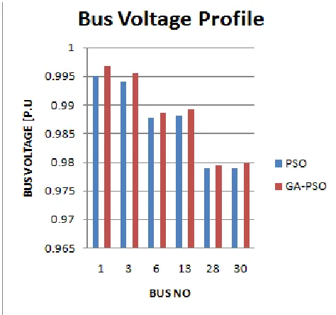
BUS Voltage Profile
[image:8.612.323.560.321.543.2]The voltage level of all the busses keep the standards level of voltages(+-5%) both with PSO and HGAPSO as shown in the figure 6 .However,the voltage is more improved by using HGAPSO
Fig 6:Bus Voltages after DFIG installation using PSO and HGAPS0
III. CONCLUSIONS
International Journal of Emerging Technology and Advanced Engineering
Website: www.ijetae.com (ISSN 2250-2459, ISO 9001:2008 Certified Journal, Volume 3, Issue 7, July 2013)
45
The HGAPSO algorithm performs the optimisation over a larger search space since it escapes from local minima and increases the diversity of variable values using the mutation operator.The HGAPSO optimises in a better way,the real and reactive power losses at the same time giving an improved voltage profile.
The numerical results shows that the intergration of the DFIG wing turbines into the traditional power distribution system is highly effective in reducing real and reactive power losses in the primary distribution System when HGAPSO is used as compared to the ordinary PSO.
In DFIG placement and sizing with the objective of optimizing real and reactive power losses ,the bus to which the DFIG domain Distributed Slack Bus Model assigns a large Combined Participation Factor is considered as the optimal site for the DFIG.
When well applied to a DFIG,the HGAPSO can be used to reduce the real and reactive power losses by 38.10% and 37.43% at the same time giving an improvement of the voltage profile by almost 0.3% .
From the tabulated results,the best locations
corresponding to the optimum size for reducing the total real and reactive power losses is in the primary distribution system.
REFERENCES
[1] C´UrcˇIc´ S., Strbac G., Zhang X.-P.: “Effect of losses in design of
distribution circuits‟, IEE Proc., Gener. Transm. Distrib, 2001, 148, pp. 343–349
[2] Ramirez-Rosado I, Bernal-Agusti´Nj, “Genetic algorithms applied to
the design of large power distribution systems”, IEEE Trans. Power Syst., 1998, 13, pp. 696–702
[3] Carrano E.G., Takahashi R.H.C., Cardoso E.P., Saldanha R.R., Neto
O.M.: “Optimal substation location and energy distribution network design using a hybrid GA-BFGS algorithm”, IEE Proc., Gener.Transm. Distrib., 2005, 152, pp. 919–926
[4] Carrano E.G., Soares L.A.E., Takahashi R.H.C., Saldanha R.R.,
Neto O.M, “Electric distribution multiobjective network design usign a problem-specific genetic algorithm”, IEEE Trans. Power Deliv., 2006, 21, pp. 995–1005
[5] Carvalho P.M.S., Ferreira L.A.F.M., Lobo F.G., Barruncho L.M.F.:
„Optimal distribution network expansion planning under uncertainty by evolutionary decision convergence‟, Electr. Power Energy Syst., 1998, 20, pp. 125–129
[6] Carrano E.G., Guimaraes F.G., Takahashi R.H.C., Neto O.M.,
Campelo F.: „Electric distribution network expansion under load-evolution uncertainty using an immune system inspired algorithm‟, IEEE Trans. Power Syst., 2007, 22, pp. 851–861
[7] Vaziri M., Tomsovic K., Bose A.:„A directed graph formulation for
the multistage distribution expansion problem‟,IEEE Trans. Power Deliv., 2004, 19, pp. 1335–1341
[8] Levitin G., Lisnianski A.: „Optimal multistage modernization of
power system subject to reliability and capacity
requirements‟,Electr.Power Syst.Res., 1999,50, pp. 183–190
[9] R. A. Walling, R. C. Dugan, J. Burke, and L. A. Kojovic. 2008,
“Summary of Distributed Resources Impact on Power Delivery Syste”, IEEE Transactions on Power Delivery, 1636-1644.
[10] C. L. T. Borges, D. M. Falcao. 3003 “Impact of distributed
generation allocation and sizing on reliability, losses and voltage profile”Proceedings of the IEEE Bolonga Power Technology Conference.
[11] T.Ackermann,G.Anderson,and L.Soder,”Distributed Generation :A
Defination,“ Electric power Systems Research ,Vol 57,pp 195-204,2001.
[12] R. Noroozian , M. Abedi and G. Gharehpetian “Combined
Operation of AC and DC Distribution System with Distributed Generation units” Journal of Electrical Engineering, vol. 61, no. 4, 2010, 193–204
[13] Kennedy J and Eberhart R, Swarm intelligence. Morgan Kaufmann
Publishers, Inc., San Francisco, CA,2001.
[14] Clerc M and Kennedy J,”The particle swarm-explosion, stability,
and convergence in a multidimensional complex space” IEEE Transactions on Evolutionary Computation,2002, 6(1):58-73.
[15] Van den Bergh F. and Engelbrecht A.P, “A Cooperative Approach to
Particle Swarm Optimization”, IEEE Transactions on Evolutionary Computation, 2004, pp. 225-239
[16] Goldberg D E, Genetic Algorithms in search, optimization, and
machine learning. Addison-Wesley Publishing Corporation, Inc, 1989.
[17] Ordonez C, „Clustering Binary Data Streams with K-means‟, In
Proceedings of DMKD, 2003, pp. 12-19.
[18] Triki E, Collette Y and Siarry P, “A theoretical study on the behavior
of simulated annealing leading to a new cooling schedule” European Journal of Operational Research, 2005, 166:pp. 77-92.
[19] K. Premalatha and A.M. Natarajan” Hybrid PSO and GA for Global
Maximization” Int. J. Open Problems Compt. Math., Vol. 2, No. 4, December 2009
[20] Luis M. Fernández,Francisco Jurado,José Ramón Saenz“Aggregated
dynamic model for wind farms with doubly fed induction generator wind turbines”Renewable Energy ,Vol .33 NO.1,PP.129-140,2008
[21] D. Santos-Martin ,S. Arnaltes,J.L. Rodriguez Amenedo“Reactive
power capability of doubly fed asynchronous generators” Electric Power Systems Research,Volume 78, Issue 11, November 2008, Pages 1837–1840
[22] Rau, N.S., and Wan, Y.-H: "Optimum location of resources in
distributedplanning"(Abstract) IEEE Trans. Power Syst., 1994, pp. 2014-2020.
[23] Willis, H.L.: "Analytical methods and rules of thumb for modeling
DG distribution interaction"(Abstract) Proc. IEEE Power Engineering Society Summer Meeting, Seattle, USA, 16-20 July 2000, pp. 1643-1644.
[24] Celli, G. Ghaiani, E. Mocci, Pilo.F, "A Multi Objective Evolutionary
Algorithm for the Sizing and Siting of distributed generation", IEEE Trans. Power Syst. 2005,Vol20,No.2.May 2005 pp. 750-757.
[25] Celli.G, Ghaian. E, Mocci.S,and Pilo.F: "A multi-objective approach
to maximize the penetration of distributed generation in distribution
networks", In Proc. June 11th -15th 2006 9th PMAPS international
Conf.,KTH Stockholm,Sweden, pp.1-6.
[26] Kamalinia, S., Afsharnia, S., et al.: "A combination of MAMD and
International Journal of Emerging Technology and Advanced Engineering
Website: www.ijetae.com (ISSN 2250-2459, ISO 9001:2008 Certified Journal, Volume 3, Issue 7, July 2013)
46
[27] W. El-Khattam, K. Bhattacharya, Y. H. Hegazy, et al.: "Optimal
investment planning for distributed generation in a competitive electricity market" (Abstract), IEEE Trans. Power Syst., 2004, pp. 1674-1684.
[28] Satish Kansal, B.B.R. Sai, Barjeev Tyagi, Vishal Kumar “Optimal
placement of distributed generation in distribution networks”, International Journal of Engineering Science and Technology,Vol. 3, No. 3, 2011, pp. 47-55
[29] Falaghi. H, Haghifam .M.-R.: "ACO based algorithm for distributed
generation sources allocation and sizing in distribution systems", in Proc. 2007 Power Tech, pp. 555-560.
[30] Soroudi. A and M.Ehsan.: "Multi objective distributed generation
planning in liberized electricity market", in IEEE Proc. 2008,PP.1-7
[31] Wang, C., and Nehrir, M.H.: "Analytical approaches for optimal
placement of distributed generation rsources in power systems", IEEE Trans. Power Syst. , 2004, 19, (4), pp. 2068-2076.
[32] Vallem, M.R., Mitra J.: "Siting and Sizing of Distributed Generation
for Optimal Micro Grid Architecture", (Abstract) in Proc. 2005
[33] .Harrison. G ,and A.R Wallace "Optimal Power Flow evaluation of
distribution network capacity for the connection of distributed generation",IEE Proc., Gener. Trans. Distrib., 2005, 152, (1), pp. 115-122
[34] J.A. Greatbanks,D. H. Popovi´c,M.Begovic,A. Pregelj andT. C.
Green, “On Optimization for Security and Reliability of Power Systems with Distributed Generation” ,IEEE Bolgna Power Tech
Conference june 23rd -26th Bolgna Italy.
[35] Alhajri, El-Hawary, M.E, "Optimal distributed generation siting via
fast sequential quadratic programming"(Abstract) in Proc. 2007
[36] Haghifam, M.-R., Falaghi, H. , Malik, O.P.: "Risk based distributed
generation placement", IET Proc., Gener. Trans. Distrib., 2007, 252-260.
[37] Carpinelli, G., Celli, G., Pilo, F and A.Russo "Distributed generation
siting and sizing under uncertainty", in Proc. 2001 IEEE Porto Power Tech Conf.
[38] Ochoa, L.F., Padiha-Feltrin, A., et al.: "Time-series-based
maximization of distributed wind generation integration",IEEE Trans. Energy Conversion, vol. 3, No. 3, pp.968-974.
[39] Hasham Khan, M. A. Choudhry. 2010” Implementation of
distributed generation algorithm for performance enhancement of distribution feeder under extreme load growth” Journal of Electrical power and energy systems, 985-997.
[40] D. Q. Hung, N. Mithulanathan and R.C. Bansal. 2010. “Multiple
distributed generators placement in primary distribution networks for loss reduction” IEEE Transactions on industrial electronics.
[41] C. Wang, M.H. Nehir. 2004. “Analytical approaches for optimal
placement of distributed generation”
[42] M. R. AlRashidi, M. F. AlHajri. 2011,”Optimal planning of multiple
distributed generation sources in distribution networks: A new approach” Energy conversion and management. 3301–3308.
[43] Naresh Acharya, Pukar Mahat, N. Mithulananthan. 2006, “An
analytical approach for DG allocation in primary distribution network. Electrical power and energy systems” 669–678.
[44] N. Mithulanathan, Than Oo , Lee Van Phu. 2004. “Distributed
generator placement in power distribution system using Genetic Algorithm to reduce losses”, Thammasat Int. J. Sc.Tech., 55-62.
[45] Deepedra Singh, Devendra Singh, K.S. Verma. 2009.
“Multiobjective optimization for DG planning with load models”,IEEE transactions on power systems. 427-436.
[46] Peter Musau Moses, Dr. Nicodemus Abungu Odero”Distributed
Slack Bus Model for a Wind-Based Distributed Generation using
Combined Participation Factors”International Journal of Emerging
Technology and Advanced Engineering,Volume 2 Issue 10 ,2012,No.80,pp 459-469
[47] H. Choi and J. C. Kim. 2000,” Network reconfiguration at the power
distribution system with dispersed generations for loss reduction” In Proc. IEEE Power Engineering Society Winter Meeting,2363– 2367.
[48] Duong Quoc Hung, Nadarajah Mithulananthan, R. C. Bansal.
2010,”Analytical expressions for DG allocation in primary distribution networks”, IEEE Transactions on energy conversion.
[49] Dheeraj Kumar Khatod, Vinay Pant, and Jaydev Sharma. “Optimal
placement of renewable energy resources based Distributed generator”, IEEE Trans. on power systems.
[50] Alireza Soroudi, Mehdi Ehsan, Raphaël Caire, Nouredine
Hadjsaid.2011,”Possibilistic evaluation of Distributed Generations impacts on Distribution Networks”, IEEE Transactions on power systems.
[51] V. H. Mendez Quezeda, Jua-Rivier Abbad, T. Gomez.
2006,”Assessment of energy distribution losses for increasing penetration of DG” IEEE Transactions on Power System, 533-540.
[52] Hasan Hedayati, S. A., Nabaviniaki, Adel Akbarimazd. 2008,”A
method for placement of DG units in distribution network”, IEEE Transactions on power delivery, 1620-1628.
[53] L. F. Ochoa, G. P. Harrison. 2011,”Minimizing energy losses:
Optimal accommodation and Smart operation of renewable DG” IEEE Trans. on Power systems. 198-205.
[54] Ziari, G., Ledwich, A., Ghosh. 2010”Optimal allocation and sizing
of DGs in distribution networks” IEEE Power and energy society general meeting. Minneapolis, Minnesota.
[55] M.F. Akorede, H. Hizam I. Aris M.Z.A. Ab. Kadir. 2011”Effective
method for optimal allocation of distributed generation units in meshed electric power systems” IET Gener. Transm. Distribution. 276–287.
[56] M. Gandomkar , M. Vakilian M. Ehsan. 2007.”A Genetic based tabu
Search algorithm for Optimal DG Allocation in Distribution Networks” Electric Power Components and Systems. 1351-1362
[57] T. Gonen et al. “Bibliography of Power Distribution System
Planning”(Abstract) IEEE Transactions on Power Apparatus and System, vol. PAS-102, no. 6 , June, 1983
[58] Acharya, N., Mahat, P., and Mithulananthan, N. “An analytical
approach for DG allocation in primary distribution
network”,(Abstract) Int. J. Electr. Power Energy Syst., 2006,28, (10), pp. 669–746
[59] Y.M. Atwa, E.F. EI-Saadany, M.M.A. Salama, R. Seethapathy.
2010. “Optimal renewable resource mix for distribution system energy loss minimization” IEEE Trans. on Power System. 360-370.
[60] E. Haesen, J. Driesen, R.Belman. 2007” Robust planning
methodology for integration of stochastic generators in distribution grids” IET Renewable power generation. 25-32.
[61] K. Nagaraju, S. Shivalingaraju, T. Ramanna, Sathyanarayanna, P.V.
![Fig 1:Equivalent circuit of a DFIG [20,21]](https://thumb-us.123doks.com/thumbv2/123dok_us/8727585.885855/4.612.332.589.484.627/fig-equivalent-circuit-dfig.webp)
![Fig 2:DFIG Capability Limits Curve[20]](https://thumb-us.123doks.com/thumbv2/123dok_us/8727585.885855/5.612.74.270.454.658/fig-dfig-capability-limits-curve.webp)