Structural Synthesis of Robot Manipulators by
Using Screw with Variable Pitch
Rasim Alizade
Department of Mechanism and Machine Theory, Azerbaijan Technical University, Azerbaijan
Copyright©2019 by authors, all rights reserved. Authors agree that this article remains permanently open access under the terms of the Creative Commons Attribution License 4.0 International License
Abstract
This paper focuses on the systematic type synthesis of parallel robot manipulators by using new structural formulas based on the screw theory. New structural formulas as a total number of screw in kinematic pairs ($), number of screws with variable pitch �$��, total number of screws that represent the contact geometry of lower and higher joint elements (t), mobility equation for robot manipulators (M), dimension of the closed loop (λ), motion of end effector of parallel manipulator (m), number degree of freedom of kinematic pairs (f), refers to find the kinematic structure of robot manipulators realizing a specified motion requirement. Twenty kinematic pairs with structural parameters �$, $�, f, t� are introduced. History of six structural formulas using for structural synthesis of parallel robot manipulators from space and different subspaces are presented as a table with equations, authors, years and some commentaries. The structural synthesis approach is based on the elementary notions of screw theory. Using the proposed of structural formulas approach, families of platform manipulators are constructed from a set of structural units. This paper is appropriate for engineers with interest in robotics, rovers, space docking parallel manipulators and screw theory.Keywords
Kinematic Pair Screws, Motion of End Effector, Screws with Variable Pitch, Dimension of Closed Loop1. Introduction
Structural synthesis of robot manipulators is the fundamental concept in robot design. The mobility of robotic mechanical system indicates the number of independent input parameters to solve the configuration of robots. If mobility of the kinematic chain is equal to zero
(𝑀= 0) and can not be split into several structural groups, we will get a simple structural group. Combining the simple platform (with 𝑛 ≥2 kinematic pairs) type structural groups with given actuators, we can get parallel
platform type robot manipulators needed to define the location (position and orientation) of end effectors. Serial platform manipulators control the motion of the platform, which are connected each other by hinges, branches, legs and other kinematic chains going from the platforms toward the frame. Complex robot manipulators consist of independent branches and legs loops with variable general constraints {𝜆𝑘}26. Many platform type robot manipulators use legs with variable general constraints. Therefore structural formulas are used by engineers for design the parallel and serial platform Euclidean robot manipulators with variable general constraints. Structural synthesis of parallel Cartesian platform robot manipulators consists from connecting the simple structural groups constructed in the orthogonal planes to actuators and moving platform. The history of formulas for structural analysis and synthesis of mechanisms and robotic mechanical systems during the second half of the 19th century, the first and second half of the 20th century and the beginning of 21st century had been investigated and illustrated in the Table by 38 equations, authors, years and commentaries in the fundamental investigations[1] and in a critical review [2]. Several investigations are described a systematic approach of structural synthesis and analysis of mechanisms by using screw theory. First investigation was given by Mueller
[3] , where in equations for simple structural group and for kinematic chains were used the number of screw in kinematic pairs. Voinea and Atanasiu [4] and Waldron
[5] introduced mobility equation of mechanisms with rank parameter equivalent to screw system of the closed loops. The scientific investigations of structural synthesis and analysis of robot manipulators by using screw theory were more dedicated in the beginning of 21st century. Huang and Li [6] proposed a type synthesis of parallel manipulators with mobility {𝑀𝑖}35 by using screw theory. Fang and Tsai
coordinates is examined by Gao et.al. [9]. An analytical method of using equivalent screw groups for structural synthesis of over constrained parallel manipulators is described in the study of Zhoo et.al. [10]. Kong and Gosselin [11−14] proposed a new way for the type synthesis of parallel manipulators with different type of end effector motions by using screw theory and virtual chain approach.
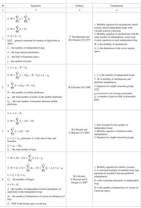
History of formulas for structural synthesis and analysis of robot manipulators given by author at.al. are presented as 6 several equations (formulas 1-6 in Table 1) with the unique key controlling parameters. In investigation [15] the mobility number, 𝜆, is a characteristic of an independent loop of robot manipulator. In Table 1 (formulas ⋕1) we have been considered mobility equation which contain mixed independent loops with variable general constraint. The history of new formula [16] about the number of independent loops was done in Table 1(formulas ⋕2). The number of independent loops in platform manipulators is described by the number of mobile platforms (B), the total number of joints on the mobile platforms (𝑗𝑏) and the total number of branches between mobile platforms (𝑐𝑏). In the paper [17] and in the Table 1.1 (formulas ⋕3) the number of independent loops is described as 𝐿=𝐶 − 𝐵, where 𝐶=𝑐𝑙+𝑐𝑏 is sum of legs and branches. A classification of parallel manipulators based on the number of mobile platforms, number of joints on the mobile platforms, number of legs and branches, and types of kinematic pairs are also presented. A new structural formulas for robots (formulas
⋕4 in the Table 1), working in Cartesian space, having three legs in orthogonal planes, introducing simple structural groups in space 𝜆= 6 and in subspaces {𝜆}35, and connected to actuators and to the end effector are introduced. Simple serial platform type structural groups in
𝜆= 3 and 𝜆= 6 are presented also in [1]. In the study
[18] new structural formulas (formulas
⋕5 𝑖𝑛𝑡ℎ𝑒𝑇𝑎𝑏𝑙𝑒1 ) for parallel and serial platform Euclidean robot manipulators with variable general constraints of branch loops and legs were presented. Selecting the legs of the robot manipulators as moving dyads on Euclidean planes the direct and inverse task will become easier to solve. The new proposed Euclidean manipulators have several legs, which create Euclidean
motions on their own Euclidean planes. The motion of the platform is defined by three independent curves of three platform points moving on three Euclidean reference planes. The general formula for motion of platforms is given also. To create new robot manipulators, simple platform structural groups with variable general constraints were considered.
This study enunciates screw system with variable pitch for the prismatic and cylindrical joints. Applying concepts the number of independent screw, number of screw with variable pitch, number of screws and motions for lower and higher kinematic pairs (Table 1.6.1) become possible to provide the structural characteristics of 20 kinematic pairs (Table 2). Two new general mobility equations for robot manipulator with mixed and the same dimension of closed loop are presented in the work (Table1.6.2 and 1.6.3).
Applying above mobility equations for structural synthesis problem the new wheeled robot that are called as “Rover” had been designed. This rover consists from moving platform and two suspensions with six wheels connected to the platform. Each suspension consist from paired two Chebyshev lambda mechanisms called bogie and one dyad called rocker. Two parallel suspensions are connected by a differential gear mechanism (Fig.2).
Table 1. Structural formulas for synthesis and analysis of robot manipulators
№ Equations Authors Commentary
1 2 3 4
1.
1. 𝑀=� 𝑓𝑖 𝑗
𝑖=1
− � 𝜆𝑘 𝐿
𝑘=1
2. 𝑀=� 𝑓𝑖 𝑗
𝑖=1
− 𝜆𝐿
3. 𝑑= 6− 𝜆
{𝑑}04 – general constraint for motion of rigid body in
space;
𝐿 – the number of independent loops;
𝜆 – the loop motion parameters;
𝑓𝑖 – the DoF of kinematic pairs;
𝑗 – the number of joints.
F. Freudenstain and R.I.Alizade [15] 1975
1. Mobility equation for mechanisms which contain mixed independent loops with variable general constraint.
2. Mobility equation of mechanisms with the same number of independent, scalar loop closure equations in each independent loop.
𝑀 is the mobility of mechanisms.
𝜆𝑘 is the dimension of the active motion space.
2.
1. 𝐿=𝑗𝑏− 𝐵 − 𝐶𝐵
2. 𝑀=� 𝑓𝑖 𝑗
𝑖=1
− 𝜆(𝑗𝐵− 𝐵 − 𝐶𝐵) +𝑞 − 𝑗𝑝
3. � 𝑓𝑖 𝑗
𝑖=1
=𝜆(𝑗𝐵− 𝐵 − 𝐶𝑏)
𝐵 – the number of mobile platforms;
𝑗𝐵 – the total number of joints on the mobile platforms;
𝐶𝑏 – the total number of branches between mobile
platforms.
R.I.Alizade [16] 1988
1. 𝐿 is the number of independent loops. 2. 𝑀 is mobility of mechanisms and platform manipulators.
3. Equation for simple structural groups {𝜆}26,
q is excessive over closing constraints,
𝑗𝑝 is number of passive DoF in kinematic
pairs.
3.
1. 𝐿=𝐶 − 𝐵
2. 𝑀=� 𝑓𝑖 𝑗
𝑖=1
− 𝜆(𝐶 − 𝐵)
3. � 𝑓𝑖 𝑗
𝑖=1
=𝜆(𝐶 − 𝐵)
𝐶=𝐶𝑙+𝐶𝑏, parameter 𝐶 is the sum of legs and
branches.
𝐶𝑙=𝑗𝐵−2𝐶𝑏
𝐶𝑙 – the total number of legs.
R.I.Alizade and C.Bayram [17] 2003
1. New formula for the number of independent loops.
2. Mobility equation of platform robot manipulators.
3. Equation for simple structural groups.
4.
1. 𝑀= (𝐵 − 𝐶)𝜆+� 𝑓𝑖 𝑗
𝑖=1
+𝑞 − 𝑗𝑝
2. 𝑀= (𝜆+ 3) +�(𝑑𝑙− 𝐷) 𝐶𝑙
𝑙=1
+�(𝑓𝑙− 𝜆𝑙) +𝑞 − 𝑗𝑝 𝐶𝑙
𝑙=1
𝐶=𝐶𝑙+𝐶𝑏+𝐶ℎ
𝐶ℎ – the number of hinges;
𝜆= 6− 𝑑;
𝜆 – the number of independent location parameters of rigid body in the independent loop;
𝑑𝑙 – the number of dimensions of vectors in subspaces of
legs.
𝑓𝑙 – DoF of the kinetic pairs on the leg.
R.I.Alizade, C.Bayram and E.
Gezgin [1] 2007
1. Mobility equation for robotic systems. 2. A structural formula of mobility loop–legs equation for parallel Cartesian platform manipulators.
𝑑 is the constraint parameter of independent loop.
[image:3.595.71.525.87.756.2]5.
1. 𝑀=𝜆+𝑗ℎ+�(𝑓𝐿− 𝜆𝐿) 𝑛
𝐿=1
+�(𝑓𝑙− 𝜆𝑙) +𝑞 − 𝑗𝑝 𝐶𝑙
𝑙=1
2. 𝑚=𝜆+𝑐𝑙+𝑗ℎ+�(𝑑𝑙− 𝐷) 𝐶𝑙
𝑙=1
+�(𝑓𝐿− 𝜆𝐿) 𝑛
𝐿=1
𝑗ℎ – the number of hinges between platforms;
𝑓𝐿 – DoF of kinematic pair on the branch-loop.
𝜆𝐿 – the motion of rigid body in branch-loop.
Rasim Alizade, Fatih Cemal Can, Erkin Gezgin [18]
2008
1. The general structural formula of serial-parallel Euclidean robot manipulators with variable general constraints.
2. The general formula for motion of platforms.
𝐷 – dimensions of vectors (𝐷= 3 for space 𝑅3,
𝑑= 2 for plane 𝑅2)
6.
1. $ =𝑓 −$�+𝑡
2. 𝑀=� 𝑓𝑃𝑓 𝜆−1
𝑓=1
− � 𝜆𝑘 𝐿
𝑘=1
+𝑞
3. 𝑀=� 𝑓𝑃𝑓 𝜆−1
𝑓=1
− 𝜆(𝐶 − 𝐵) +𝑞
4.𝑀=𝜆+� �� 𝑓𝑃𝑓 𝜆−1
𝑓=1
− 𝜆𝑙� 𝑐𝑙
𝑙=1
+� �� 𝑓𝑃𝑓 𝜆−1
𝑓=1
− 𝜆𝑏� 𝐿𝑏
𝑏=1
+𝑗ℎ
5.𝑚=𝜆+𝑐𝑙+𝑗ℎ+�(𝑑𝑙− 𝐷) 𝑐𝑙
𝑙=1
+� �� 𝑓𝑃𝑓− 𝜆𝑏 𝜆−1
𝑓=1
�
𝐿𝑏
𝑏=1
6.𝑀=𝜆+�� 𝑓𝑃𝑓− 𝜆𝑙 𝜆−1
𝑓=1
� 𝑐𝑙+��𝑓𝑃𝑓− 𝜆𝑏� 𝜆−1
𝑓=1
𝐿𝑏+𝑗ℎ
7.𝑚=𝜆+𝑐𝑙+𝑗ℎ+ (𝑑𝑙− 𝐷)𝑐𝑙+�� 𝑓𝑃𝑓 𝜆−1
𝑓=1
− 𝜆𝑏� 𝐿𝑏
𝑡 – represents the number of screws that describe the contact geometry of joint elements.
𝑡= 2 – contact elements on surface;
𝑡= 3 – contact elements on line;
𝑡= 4 – contact elements on points;
Rasim Alizade 2017
1. Total screws in kinematic pair. 2. Mobility equation for robot manipulators with variable loop motion parameters. 3. Mobility equation with the same dimension in each independent loop.
4. Structural formula for Euclidean platform type robot manipulators with variable general constraints.
5. Structural formula that describe the motions of end effector on the parallel robot manipulators.
6. Mobility equation for Euclidean manipulators with constant general constraint.
7. Motion of end effector of Euclidean manipulator with constant general constraint.
2. Introduction to Screw with Variable
Pitch
The structural and kinematic analysis and synthesis problem have been studying with the goal of identified new methods for composing robot manipulators capable of performing various prescribed positions and orientations of the end effectors. Screw with variable pitch can represent the prismatic joint, P, with the variable pitch parameter
𝜇𝑃=∞, and also the cylindrical joint 𝐶(𝑅𝑃) with variable
pitch 𝜇𝐶= (∞; 0) that describe a rotation motion
(𝜇𝑅= 0) and translation motion 𝜇𝑃=∞.
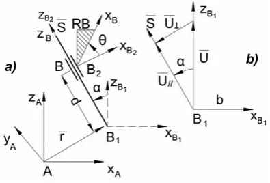
As shown in Fig. 1, the location of a rigid body (𝑅𝐵) of the cylindrical joint can be described by the three parameters for position (𝑥,𝑦,𝑧) and three independent parameters (𝑑,𝛼,𝜃) for orientation. Let coordinate system A and was then translated parallel to the point 𝐵1 (Fig. 1a). The position of point 𝐵1 is described by vector 𝑟̅(𝑥,𝑦,𝑧).
Next, the system 𝐵2 that is initially aligned with system
𝐵1 is rotated by the twist angle 𝛼 about the 𝑥𝐵1 axis. Following this the coordinate system 𝐵2 of rigid body is translated along the 𝑧𝐵2 axis by a distance 𝑑. Lastly the coordinate system 𝐵 that was firstly aligned with the system 𝐵2 is rotated by the angle 𝜃 around 𝑧𝐵, so we will get orientation of the coordinate system 𝐵𝑥𝐵𝑦𝐵𝑧𝐵.
Transformation of one coordinate system 𝐵 to a reference coordinate system 𝐴 correspond to the transformation of screw $, when the relative position and orientation of the pair of screws are known (Fig. 1a). By using homogeneous coordinates the transformation of the system will be represented by 4×4 matrix as:
𝑇
𝐵
𝐴 =�
1 0 0 𝑥
0 1 0 𝑦
0 0 1 𝑧
0 0 0 1
� �
1 0 0 0
0 𝑐𝛼 −𝑠𝛼 0
0 𝑠𝛼 𝑐𝛼 0
0 0 0 1
� �
1 0 0 0 0 1 0 0 0 0 1 𝑑̃
0 0 0 1
�
𝑐𝜃� −𝑠𝜃� 0 0
𝑠𝜃� 𝑐𝜃� 0 0
0 0 1 0 0 0 0 1
�=�
𝑐𝜃� −𝑠𝜃� 0 𝑥
𝑠𝜃�𝑐𝛼 𝑐𝜃�𝑐𝛼 −𝑠𝛼 𝑦 − 𝑑̃𝑠𝛼
𝑠𝜃�𝑠𝛼 0 𝑐𝛼 𝑧+𝑑̃𝑐𝛼
0 0 0 1
�
(1) where: 𝑆𝜃 and 𝐶𝜃 represent the sine and cosine of 𝜃, and
𝑆𝛼 and 𝐶𝛼 represent the sine and cosine of 𝛼.
Knowledge of these six parameters (𝑥,𝑦,𝑧,𝛼,𝑑,𝜃) completely defines the position and orientation of the 𝐵 coordinate system attached to the rigid body of the cylindrical joint and measured with respect to the 𝐴 coordinate system as shown in Eq.(1). The location of rigid body reduce a single vector 𝑆̅//𝑍̅𝐵 and a couple moment
𝑈�//𝑍𝐵1 at point 𝐵1 with a twist angle 𝛼 (Fig. 1b). The couple moment 𝑈�=𝑟̅×𝑆̅ may be resolved into two components: one 𝑈�//collinear with joint vector 𝑆̅ in the direction by twist angle 𝛼. The perpendicular component
𝑈�⊥ will rotate rigid body around cylindrical joint vector 𝑆̅
by rotation angle 𝜃, so 𝜃̅=𝜃𝑆̅.
The twist angel 𝛼 was defined between vectors 𝑆̅ and
𝑈� (Fig. 1b) mesured in a right-hand sense about 𝑥̅𝐵1. The rotation angle 𝜃 was defined between 𝑥̅𝐵2 and 𝑥̅𝐵 measured in a right hand sense about 𝑆̅ (Fig. 1a). It is known that, there are two distinct angles between 0 and
2𝜋 that will have the same cosine value. So, the expressed for the cosine and sine of 𝛼 and 𝜃 can be expressed by Eqs. (2):
�𝑐𝑜𝑠 𝛼𝑠𝑖𝑛 𝛼==�𝑈𝑈 ∙ 𝑆× 𝑆� ∙ 𝑥̅
𝐵1
�sincos𝜃𝜃==�𝑥̅𝑥̅𝐵∙ 𝑥̅𝐵2
𝐵×𝑥̅𝐵2� ∙ 𝑍̅𝐵 (2) As show in Fig. 1, the axes of the cylindrical joint 𝑆̅ and a couple moment 𝑈�// has the same line. Thus the combination of a collinear vector 𝑆̅ and a couple moment
[image:5.595.76.274.505.639.2]𝑈�// is called a screw or wrench.
Figure. 1. Kinematic model of cylindrical joint
So, the screw with variable pitch has both a translation 𝑑 and rotation 𝜃 about the axis 𝑆̅ described by twist angle
𝛼. Parameters 𝑑, 𝜃 and 𝛼 are independent parameters of rigid body motion respect to screw $� with variable pitch.
Two collinear vectors 𝑆̅ and 𝑈�// uniqually determine the position and orientation of the screw with variable pitch.
𝑆̅ is an axis vector and 𝑈�// is moment of screw 𝑆̃, where
𝑆̅ defines the direction of motion of screw $� and moment
𝑈�// determines the rotation around the axis. Unit vector 𝑆̅
and moment 𝑈�// can be introduced as dual vector that is called a screw with variable pitch:
$�=𝑆̅+𝜀�𝑈�//+𝜇�𝑆̅� (3)
where 𝜀2= 0 is operator of Clifford.
The ratio of joint position d and joint rotation 𝜃 in cylindrical joint reduce to the following variable pitch:
𝜇�=𝑑𝜃 (4) As shown in Fig. 1b the rotation moment in cylindrical joint reduce to expression as follow:
𝑈�//=𝑈� ∙cos𝛼= (𝑟̅×𝑆̅) cos𝛼 (5)
Hence, using Eqs. (3 ÷ 5) the vectors 𝑆̅ and resultant couple moment 𝑈� describing location of a rigid body with cylindrical joint can be descried as a screw with variable pitch:
$�=� 𝑆(𝑟̅̅ ×𝑆̅) cos𝛼+𝜇�𝑆̅� (6)
So, as shown in Eq. (6), six independent components
(𝑥,𝑦,𝑧,𝛼,𝑑,𝜃) describe the location of screw with variable pitch. As shown in Eq. (7) the couple moment 𝑈� of the screw with variable pitch is:
𝑈�= (𝑟̅×𝑆̅) cos𝛼+𝜇�𝑆̅ (7) Since the screw axis and its moment are in orthogonal planes and unit of screw with variable pitch �$��= 1, so
𝑆̅ ∙(𝑟̅×𝑆̅) = 0 and 𝑆̅ ∙ 𝑆̅= 1 (8) Multiplying both side of Eq.(7) to the vector 𝑆̅ we get the following equation:
𝑆̅ ∙ 𝑈�= (𝑟̅×𝑆̅)∙ 𝑆̅cos𝛼+𝜇�𝑆̅ ∙ 𝑆̅ 𝑜𝑟 𝜇�=𝑆̅∙𝑈�𝑆̅∙𝑆̅ (9) For revolute, prismatic, screw and cylindrical joints the parameters of pitch to Eq.(8) can be described as follows:
𝜇𝑅= 0, 𝜇$=𝑑𝜃, 𝜇�𝑝=∞, 𝜇�𝐶= {0,∞}.
3. Structural Formulas for Robot
Manipulators by Using Screw
Theory
formula for robot manipulators by using screw theory allows to solve the structural synthesis with variable general constraints including platforms, hinges, legs and branch loops with different ranks, that is introduced from different subspaces and spaces.
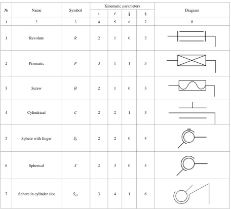
It is known that two rigid bodies attached to each other by surfaces are formed lower kinematic pairs, otherwise if contact geometry of two rigid bodies is line or a point are formed higher kinematic pairs. Due to the fact that the unconstraint space has dimension 𝜆= 6 with independent motions 3R3P, but dimension of over constraint subspaces is 𝜆= 2 ÷ 5 with different angular and linear or just angular conditions in the loops of robot manipulators. Usually kinematic pairs need constraints 𝑐= 1 ÷ 5 in order to be defined properly degree of freedom 𝑓=𝜆 − 𝑐. Each kinematic pair has input and output link screws and joint independent screws $ with constant pitch 𝜇 ,
however some joints with translation motions has additional variable screws $� with variable pitch 𝜇�.
The simple planar surface can be represented by two parallel screws $1$2 or two orthogonal screws $1⊥$2, so for lower kinematic pairs number of screws 𝑡= 2. The intersection of two planar surfaces $1$2 and $2$3 will be result in a line represented by $1$2$3 or as $1⊥$2⊥$3 so for higher kinematic pair with line contact of elements the number of screws 𝑡= 3. The intersection of three planar surfaces that will be result in a point can be represented by four screws $1$2$3→$2⊥$4 or as $1⊥$2⊥$3⊥$4, so for higher kinematic pair with point contact of elements the number of screws 𝑡= 4. Elements of the structural bonds can be illustrated as " " describe the parallel of screws and
[image:6.595.70.527.312.725.2]“⊥” describe the perpendicular of screws.
Table 2. Joints kinematic parameters
№ Name Symbol
Kinematic parameters
Diagram
t f $� $
1 2 3 4 5 6 7 8
1 Revolute 𝑅 2 1 0 3
2 Prismatic 𝑃 3 1 1 3
3 Screw 𝐻 2 1 0 3
4 Cylindrical 𝐶 2 2 1 3
5 Sphere with finger 𝑆𝑓 2 2 0 4
6 Spherical 𝑆 2 3 0 5
8 Sphere in
torus slot 𝑆𝑡𝑠 3 4 0 7
9 Plane to slope line 𝐹/𝐿 4 4 1 7
10 Plane to perpendicular line 𝐹⊥𝐿 4 3 1 6
11 Plane to parallel lines 𝐹//𝐿 3 4 2 5
12 Line to Sphere 𝐿𝑆 4 4 1 7
13 Cylinder to plane 𝐶𝐹 3 4 2 5
14 Cylinder to torus 𝐶𝑡 4 4 1 7
15 Sphere to plane 𝑆𝐹 4 5 2 7
16 Hyperboloid to Sphere 𝐻𝑠 4 5 2 7
17 Sphere to Torus 𝑆𝑡 4 5 2 7
19 Torus to torus 𝑇𝑡 4 5 2 7
20 Sphere to sphere 𝑆𝑠 4 5 2 7
The usage of recurrent screws in the study of kinematic pairs can clarify the motion concept easily. From this point of view the number of independent screws in kinematic pairs can be introduced as follow:
$ =𝑓 −$�+𝑡 (9) where:
$�= number of screws with variable pitch;
𝑡= number of screws of lower (𝑡= 2) or higher kinematic pairs (𝑡= 3 for line and 𝑡= 4 for point contact of elements);
𝑓= degrees of freedom of relative motion permitted at joint.
The twenty kinematic pairs of robot manipulators in all types, symbols, kinematic parameters and their diagrams are shown in Table 2. Using Eq.(9) and (1.1) from Table 1 we can introduce a new general mobility equation for mechanisms with mixed dimensions of closed loops as:
𝑀=∑𝜆−1𝑓=1𝑓𝑃𝑓− ∑𝐿𝑘=1𝜆𝑘+𝑞 (10)
where 𝜆𝑘− number of independent, scalar, loop closure equations associated with k-th independent loop;
𝑃𝑓 is the number of 𝑓 mobility joints. 𝑓= $ + $� − 𝑡 is
DoF at joint;
𝑞= number of depended constraint equations.
As show in Table 1, the number of independent loops
𝐿=𝑐 − 𝐵, so mobility Eq. (10) can be introduced as mobility equation for robot manipulators with the same number of independent, scalar loop closure equation in each independent loop:
𝑀=∑𝜆−1𝑓=1𝑓𝑃𝑓− 𝜆(𝐶 − 𝐵) +𝑞 (11)
where 𝐶=𝑐𝑙+𝑐𝑏 is the sum of legs and branches; 𝐵= number of mobile platforms.
The overall performance of robots and rovers are usually constructed from the multiple platforms, hinges leg and branch loops with variable general constraint parameters, describing the location of rigid body. These robots and rovers can be affected by the topology of their possible mechanical structures. The motions (rotation and translation) of rigid links and platforms of the manipulators could be described in space 𝑅3 and in plane 𝑅2 with dimensions of vectors 𝐷= 3 and 𝐷= 2 in reference
frame respectively. The location of rigid body in the three dimensional space 𝑅3 can be obtain by Euclidean motions of the two dimensional subspaces 𝑅2. It is known that the location of rigid body in space 𝑅3 can be determined minimum by three independent curves of the three points of moving rigid body. Let there are dyads kinematic chains on each Euclidean “3≤ 𝑝𝑙𝑎𝑛𝑒𝑠 ≤6”. If these kinematic chains of Euclidean planes are joined to the moving rigid body by spherical or spherical-torus kinematic pairs, so we will attain location of the rigid body in the three dimensional space 𝑅3.
The general structural formula for parallel-serial Euclidean platform type manipulators with variable general constraints [18] including hinges (𝑗ℎ), leg (𝑙) and branch (𝐿𝑏) loops can be also formulated in the form as (Table 1):
𝑀=𝜆+∑ �∑𝑐𝑙=1𝑙 𝜆−𝑓=11𝑓𝑃𝑓− 𝜆𝑙�+∑ �∑𝐿𝑏𝑏=1 𝜆−𝑓=11𝑓𝑃𝑓−
𝜆𝑏�+𝑗ℎ (12)
where 𝜆 is the dimension parameter of moving platform;
𝜆𝑙 and 𝜆𝑏 are dimension parameters of leg and branch
loops; 𝑗ℎ is the number of hinges between platforms. The structural formula for motion [18] of platforms that are created by mechanical system from different Euclidean planes can be introduced in the following form (table 1):
𝑚=𝜆+𝑐𝑙+𝑗ℎ+∑𝑙=1𝑐𝑙 (𝑑𝑙− 𝐷)+∑ �∑𝐿𝑏=1𝑏 𝜆−1𝑓=1𝑓𝑃𝑓−
𝜆𝑏� (13)
where 𝑑𝑙 is the number of dimensions of vectors of the legs in Euclidean planes;
D is the number of dimensions of vectors in the reference frame.
If the number of independent scalar leg-closure equations identical in each Euclidean planes and identical in each branch loops, the general structural formula (12) for Euclidian manipulators can be defined as
𝑀=𝜆+�∑𝜆−1𝑓=1𝑓𝑃𝑓− 𝜆𝑙�𝑐𝑙+∑𝜆−1𝑓=1�𝑓𝑃𝑓− 𝜆𝑏�𝐿𝑏+𝑗ℎ
following from:
𝑚=𝜆+𝑐𝑙+𝑗ℎ+ (𝑑𝑙− 𝐷)𝑐𝑙+�∑𝜆−1𝑓=1𝑓𝑃𝑓− 𝜆𝑏�𝐿𝑏 (15)
4. Structural Synthesis of 6DoF
Parallel Docking Manipulator of
Spacecraft
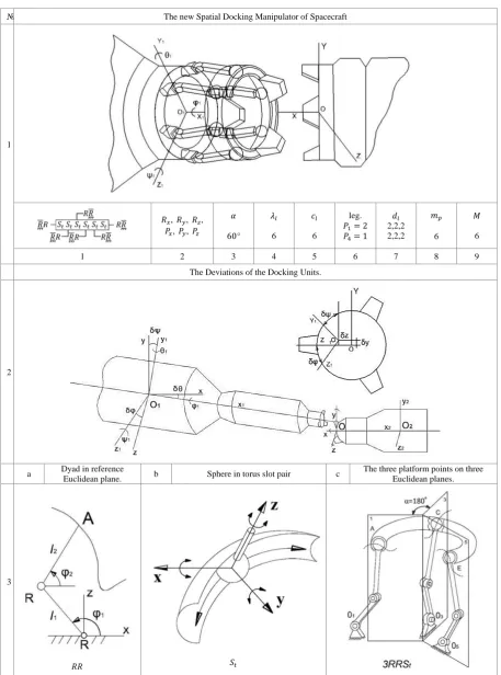
In space flights the orbital docking system is used. The use of an orbital station with two docking units ensures a rigid connection with the formation of a hermetically sealed tunnel. A large number of interacting mechanisms are concentrated in the docking aggregates. The multi-functionality of the working bodies requires the solution of the problem of the structural synthesis of spatial manipulators of coupling aggregates. Since the mechanisms operate in open space, it is therefore necessary to develop new manipulators, nodes and elements of kinematic pairs. Structural parameters, kinematic structure, motion of platform and 3D drawing of the spaces docking manipulators 6𝑅𝑅𝑆𝑡 is depicted in Table 3. Controllable space vehicles are brought to a touch with a certain speed and position, after which the process of docking with a spatial manipulator of a parallel structure begins, which ends with a rigid connection of two docking units. After the end of the flight, an undocking takes place by releasing the mechanical connections of the docking device of the platform manipulator from the orbital station (Table 3.1).
When docking it is required that the coaxial position of the docking assemblies and the zero linear and angular velocities be maintained. The possible values of the relative coordinates and their first derivatives in the case of mechanical contact are called the initial conditions of the docking. Deviations from the co-axial position (Table 3.2) are determined by the linear coordinates 𝛿𝑦, 𝛿𝑧 and planar angles 𝛿𝜓, 𝛿𝜑, 𝛿𝜃. The total deviations of the docking units from the co-axial position are added from the errors: unit settings, measurements and control dynamics. Electromechanical docking devices have been created to reduce errors based on electromechanical dampers. With the damping, the brake robot can accelerate in a unit of millisecond to a speed of several thousand revolutions per minute.
The new four proposed Euclidean docking manipulators have identical legs as plane dyads RR as shown in Table 3.3a. Each end of dyads connect to the moving platform by spherical-tours pairs. Kinematic pair with 4DoF is introduced as sphere in torus slot pair 𝑆𝑡𝑠 that perform three rotations and one circular translation (Table 3.3 b). Note that, end points of each dyads respect to the fixed reference frame (Table 3.3 c) define the curve of one point
of the platform in the reference Euclidean plane. Three legs
𝑅𝑅𝑆𝑡𝑠 of the moving platform defines the three reference
Euclidean planes (Table 3.3 c) that are located under an angle of 120°. It is known that the location of the moving rigid body in space can be defined by minimum three independent curves of three rigid body points moving on three Euclidean reference planes.
Since the Euclidean parallel docking manipulator consist of a movable platform and legs, then the number of branch-loops 𝐿𝑏 = 0, hinges 𝑗ℎ= 0 and 𝜆𝑙=𝑐𝑜𝑛𝑠𝑡, so Eq. (14) takes the form:
𝑀=𝜆+�∑𝜆−1𝑓=1𝑓𝑃𝑓− 𝜆𝑙�𝑐𝑙 (16)
In the same way when 𝐿𝑏= 0, 𝑗ℎ= 0 and 𝑑𝑙=𝑐𝑜𝑛𝑠𝑡, then the formula (15) for motion of platform of Euclidean docking manipulator can be written in the form
𝑚=𝜆+ (1 +𝑑𝑙− 𝐷)𝑐𝑙 (17)
Example 1.
Design a parallel Euclidean docking robot manipulator with 𝜆= 6, 𝜆𝑙= 6, 𝑐𝑙= 6, 𝑀= 6. Find both the number and kind of kinematic pairs on each leg. Also, find the motion of docking platform.
By using Eq.(16) total DoF and kind of kinematic pairs of the legs can be calculated as
(𝑀 − 𝜆)𝑐𝑙−1+𝜆𝑙=� 𝑓𝑃𝑓 5
𝑓=1
𝑜𝑟
6 =𝑃1+ 4𝑃4, 𝑜𝑟 𝑃1= 2 𝑎𝑛𝑑 𝑃4= 1
so that, in the designed docking manipulator, each leg will consist of two kinematic pairs with one degrees of freedom (revolute pairs RR) and one kinematic pair with four degrees of freedom (sphere in torus slot pair 𝑆𝑡𝑠). By using Eq.(17), the motion of the docking platform will be 𝑚= 6, it means motion of platform will 𝑅𝑥, 𝑅𝑦, 𝑅𝑧, 𝑃𝑥, 𝑃𝑦, 𝑃𝑧.
Kinematic structure with different structural parameters of Euclidean docking robot manipulator with six legs is shown in Table 3.1.
The above procedure can be used for Euclidean docking robot manipulators with three, four and five legs.
The result of the new Euclidean docking robot manipulators are shown in Table 4. Elements of the structural bonds can be illustrated as: Restangle (▭):
describes moving platform with spherical-torus pairs 𝑆𝑡. Platform leg (−,∟): connection of the spherical-torus pairs on the moving platform with pairs of the legs.
: input joint on fixed frame.
Table 3. Parallel Euclidean Platform Spacecraft Docking Manipulator
№ The new Spatial Docking Manipulator of Spacecraft
1
𝑅𝑥, 𝑅𝑦, 𝑅𝑧,
𝑃𝑥, 𝑃𝑦, 𝑃𝑧
𝛼
60°
𝜆𝑙
6
𝑐𝑙
6
leg.
𝑃1= 2
𝑃4= 1
𝑑𝑙
2,2,2 2,2,2
𝑚𝑝
6
𝑀
6
1 2 3 4 5 6 7 8 9
The Deviations of the Docking Units.
2
a Dyad in reference
Euclidean plane. b Sphere in torus slot pair c
The three platform points on three Euclidean planes.
3
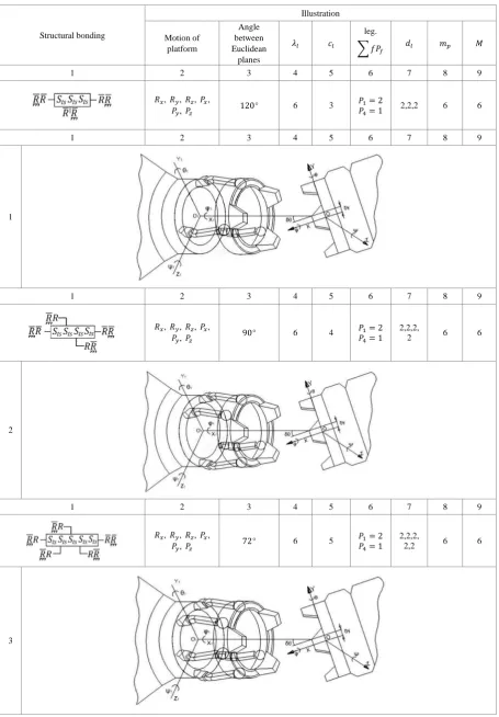
[image:10.595.70.528.90.707.2]Table 4. New 6DoF Parallel Docking Manipulators of Spacecraft
Structural bonding
Illustration
Motion of platform
Angle between Euclidean
planes
𝜆𝑙 𝑐𝑙
leg.
� 𝑓𝑃𝑓 𝑑𝑙 𝑚𝑝 𝑀
1 2 3 4 5 6 7 8 9
𝑅𝑥, 𝑅𝑦, 𝑅𝑧, 𝑃𝑥,
𝑃𝑦, 𝑃𝑧 120° 6 3
𝑃1= 2
𝑃4= 1 2,2,2 6 6
1 2 3 4 5 6 7 8 9
1
1 2 3 4 5 6 7 8 9
𝑅𝑥, 𝑅𝑦, 𝑅𝑧, 𝑃𝑥,
𝑃𝑦, 𝑃𝑧 90° 6 4
𝑃1= 2
𝑃4= 1
2,2,2,
2 6 6
2
1 2 3 4 5 6 7 8 9
𝑅𝑥, 𝑅𝑦, 𝑅𝑧, 𝑃𝑥,
𝑃𝑦, 𝑃𝑧 72° 6 5
𝑃1= 2
𝑃4= 1
2,2,2,
2,2 6 6
[image:11.595.71.527.93.748.2]5. Structural Synthesis of Wheeled
Robots
It is obvious that wheeled robot have been developed for Mars and Moon surface. First we consider the definition of wheeled robot: “A wheeled robot is an autonomous system capable of traveling a terrain with natural or artificial obstacles”. As shown in Fig. 2.1 kinematic structure of wheeled robot has six wheels with symmetric structure for both sides. Each side has three wheels which are connected to each other by the main linkage and two loops kinematic chain. Main linkage called rocker that has two joints, where first joint connected to back wheel and second joint assembled to platform. The rocker is kinematic chain where the second path of link connected rigidly to another linkage system with two wheels. The second linkage system is called bogie (Fig. 2.2). So, rocker-bogie kinematic chain is called suspension system. Wheeled rough terrain mobile robots are called as “Rover”. Rovers can carry more weight with high-speed, easy novigation and more precisely can be calculated position and orientation. First rover was “Lunakhod” and second rover was six wheeled syspension system, which connects the wheels to the platform. This connection are linkage mechanisms, damping and complex spring.
The new bogie mechanism consists of two Chebyshev lambda mechanisms which are connected symmetrically. Paired two lambda mechanisms are used as motion generation mechanisms, where couplers are input links. To move the coupler points 𝑀1 and 𝑀2 along a line sufficiently and necessary to fulfil the design relation:
3𝑑 − 𝑎= 2𝑏. The length of parametre 𝑑 can be changed according to relation 1,55𝑎 ≤ 𝑑 ≤3𝑎 (Fig. 2.1). The same second suspension kinematic chains are assembled in opposite side of moving platform. Right and left suspensions are connected to each other by a differential gear mechanism (Fig. 2). When one side climbing over obstacle, this mechanism rotates the platform around the rocker joints by average angle of two sides (Fig. 2.1). So, the wheeled robot is equipped with six wheels and possibly a manipulator setup mounted on the platform for handling of work pieces, tools or special devices. On inclined surface the moving rover can hold the main plarform horizontal. Navigation gets easier by this feature of rover.
Rovers are driven by commands which are sent from ground operators after tested in 3𝐷 computer simulation. Some of the critical motions such as climbing high slope, new rover designs are needed to more flexible duaring field operation.
Example 2
Design a parallel wheeld rover with six legs cl = 6, three branch cb = 3 and one moving platform B = 1 (Fig. 2.1). The dimension parameter of each independent loops on the left and right suspensions {λk}18= 3 (Fig. 2.2). The number of kinematic pairs with one DoF in the left and right suspensions P1= 30. Two suspensions kinematic chains are connected by differential gear mechanism. Find the number of motors for parallel whelled rover. Also, find the motion of the rover’s platform.
First, we define the number of independent loops (Table 1.3):
L = C−B = cl+ cb−B = 6 + 3−1 = 8.
Using Eq. (11) total DoF of parallel wheeled rover can be calculated as
M =�f
5
f=1
Pf− λ(C−B) = P1− λ(cl+ cb−B)
= 30−3(6 + 3−1) = 6.
By using Eq.(17), the motion of the moving rover’s platform can be defined as
m =λ+ (1 + dl−D)cl= 6 + (1 + 2−3) = 6.
Thus, the problem of the structural synthesis of the wheeled rocker-bogie mechanism is solved and it is introduced in Fig.2. Spring and damper application to double lambda bogie good solution for high-speed off-road vehicles.
1
a b c
2
Figure 2. Kinematic model of rocker-bogey mechanism
6. Conclusions
The problem of structural synthesis of the robot manipulators with variable general constraint of the legs and closed loops can be difficult and complex task depends on the DoF and motion of an end-effector concept. It is described a new structural formula of kinematic pairs for robot manipulators by using screw with variable pitch. From this point the twenty kinematic pairs are shown with types, simbols, kinematic screw parameters and their diagrams. It were introduced two new general mobility equations for mechanisms with mixed or fixed dimensions of close loops. The general structural formula for Euclidean manipulators with variable or identical general constraints are introduced. The new structural formula for motion of end effector of robot with legs from different Euclidean planes were considered. Four new Euclidean 6DoF parallel docking manipulators of Spacecraft were reviewed and synthesized. Funally, by using sistematic process of structural synthesis by using for mobility of robot and motion of moving platform were developed to create new structure of wheeled robot-rover for Mars and Moon surface.
REFERENCES
[1] Rasim Alizade, Cagdas Bayram, Erkin Gezgin, Structural Synthesis of serial platform manipulators, IFToMM J., Mechanism and Machine Theory 42 (2007) 580-599. [2] G. Gogu, Mobility of mechanisms: a critical review,
IFToMM J. Mech. Mach. Theory 40 (2005) 1068-1097. [3] R.Muller, Die zwanglanfigkeit kinematische ketten,
Unpublished dissertation (1920), as quoted in K. Federhofer: Graphische Kinematic and Kinetostatic, Springer, Berlin, 1932.
[4] R. Voinea, M. Atanasiu, Contributions a la theorie geometrigue des vis, Bull. Inst. Politech. Bucuresti XXI (3) (1959).
[5] K. J. Waldron, The constraint analysis of mechanisms, J. Mech. 1 (1966) 101-114.
[image:13.595.68.526.87.452.2][7] Yuefa Fang, Lung-Wen Tsai, Structure synthesis of a class of 4-DoF and 5-DoF parallel manipulators with identical limb structures, Int. J. Robot. Res. 21 (2002) 799-810. [8] Y. Jin, I. M. Chen, G. Yang, Structure synthesis and
singularity analysis of a parallel manipulator based on selective actuation. Proceeding of the International Conference on Robotics and automation (2004) 4533-4538. [9] F. Gao, W. Li, X. Zhao, Z. Jin, H. Zhao, New Kinematic
structures for 2-5 DoF parallel manipulator designs, IFToMM J, Mechanism and Machine Theory 37 (2002) 1395-1411.
[10]T. S. Zhao, J. S. Dai, Z. Huang, Geometric analysis of over constrained parallel manipulators with 3-4 DoF, ASME Journal Series C, Vol. 45, No. 3, (2002) 730-740.
[11]X. Kong, C. M. Gosselin, Type Synthesis of 3T1R 4-DoF parallel manipulators based on screw theory, IEEE Transactions on Robotics and Automation, Vol. 20, No. 2, April (2004) 181-190.
[12]X. Kong, C. M. Gosselin, Type synthesis of 4-DoF SP-equivalent parallel manipulators: A virtual chain approach, IFToMM J., Mechanism and Machine Theory, 41 (2006) 1306-1329.
[13]X. Kong, C. M. Gosselin, Generation of parallel manipulators with three translational degrees of freedom based on screw theory, Proceedings of Symposium on Mechanisms, Machines and Mechatronics, Montreal, Canada (2001).
[14]X. Kong, C. M. Gosselin, Type synthesis of parallel mechanisms, Springer (2007).
[15]F. Freudenstein, R. Alizade, On the degree of freedom of mechanisms with variable general constraint, IV World IFToMM Congress, England,(1975) 51-56.
[16]R. I. Alizade, On the degree of freedom of kinematic chain, Az. Pol. Inst., Automation design of mechanisms, manipulator and robots, Baku (1988) 3-14.
[17]Rasim Alizade, Cagdaş Bayram, Structural synthesis of parallel manipulators, IFToMM J. Mech. Mach. Theory 39 (2004) 857-870.