Experimental and Numerical Study of Heat Transfer
Process of Chilled Water Storage Tank
Firas M. Hasan,
Maathe Abdulwahed Theeb
*Mechanical Engineering Department, Faculty of Engineering, Al-Mustansiriyah University, Iraq
Copyright©2018 by authors, all rights reserved. Authors agree that this article remains permanently open access under the terms of the Creative Commons Attribution License 4.0 International License
Abstract
Cool thermal energy storage using thermal stratification becomes one of the widespread applications because of the ability to shift the electrical cooling loads from on-peak to off-peak periods and significantly contributes to reducing the capacity of the refrigeration system and operating costs. Seven flow rate tests varying from 1.5 to 7.5 l/min for charging cycle were performed on small-scale vertical cylindrical storage tank equipped with three primary inlet diffusers, an elbow, two-ring linear and radial circular diffusers. The storage tank with inlet diffusers was assessed using temperature distributions and performance measures including thermocline thickness(ht), the half-cycle figure of merit (𝐹𝑂𝑀½) and equivalent lost tank height (ELH). Commercial finite volume code was used to predict temperature distributions in a stratified water tank model, temperature data acquired from experimental tests and simulation models were compared for validation purpose. The results suggested that the storage tank with two-ring linear circular diffuser produced better performance and higher stratification than two-ring radial circular diffuser for various flow rates by 1.4%𝐹𝑂𝑀½, 20.6% ELH and 10.6% ht, and much better than an elbow diffuser by 1.7%𝐹𝑂𝑀½, 24% ELH and 31.1% ht, furthermore, the degree of mixing was affected essentially the flow velocity which in turn causes an increase or decrease in thermocline thickness. Temperature distributions obtained from finite volume model are found to be in very close agreement with those obtained experimentally.Keywords
Thermal Energy Storage, Stratification, Inlet Diffusers, Performance Metrics, Validation1. Introduction
The peak electrical demand occurs in daytime due to using air conditioning systems specialized for cooling buildings, these systems consume up to 70% of electric energy [1] due to high ambient temperature, this can be
practical applications that produce good stratification are radial and octagonal diffusers. Most storage tanks used with these diffusers are vertical cylindrical tanks either concrete or steel tank because the tank wall is subjected to less bending momentum in addition to the lower surface to volume ratio [3].
Many experiments have been carried out to study the effect of the diffuser based on parameters and dimensions which in turn improves thermal stratification. Wildin and Truman, 1985 [4] presented a series of experimental tests on three scale-model rectangular chilled water storage tank equipped with an H-shaped diffuser, linear diffuser and a flexible membrane, all are assessed using thermal efficiency. They showed that the chilled water tanks with diffusers and membrane are stratified well with thermal efficiency up to 90%. Yoo et al., 1986 [5] conducted experiments on a scale-model rectangular chilled water storage tank to study and identify the factors influencing thermocline formation, they found that the primary factor in thermocline formation is density current, and also they found that the inlet densimetric Froude number is a governing parameter in thermocline formation and besides they showed that the inlet Froude number of no more than 2 is appropriate for diffuser design. Tran et al. 1989 [6] investigated the performance of four chilled water storage systems including natural stratification, diaphragm, empty tank and labyrinth systems during the charging and discharging cycles using the figure of merit. They demonstrated that all systems get good separation between warm and cold water with a good value of the figure of merit that ranges from 85 to more than 95%. Wildin and Truman, 1989 [7] performed experimental tests on scale model cylindrical stratified chilled water storage tank equipped with radial diffuser during a complete cycle, test results indicated that the storage tank with radial diffuser produced good thermal performance and well stratification at flow rate corresponding to inlet Froude number of 2. Also, they found that the mixing that occurs near the inlet diffuser relies on inlet Reynold number and Froude number.
Wildin, 1989 [8] investigated experimentally the performanceof stratified vertical cylindrical chilled water storage tank with three inlet diffusers, small and large radial diffusers, and octagonal diffuser with an inlet Froude number equal to unity. He revealed that all diffusers fitted out in a storage tank produced satisfactory stratification and good thermal performance, furthermore, he compared between three inlet diffusers to make sure which one of inlet diffusers attain higher stratification, the results indicated that the small radial diffuser produced most mixing during thermocline formation, the large radial diffuser produced less mixing and octagonal diffuser produced the least mixing. Dorgan and Elleson, 1993 [3]
determined the design criteria of inlet diffuser in which the inlet densimetric Froude number equal to unity and the inlet Reynolds number is defined based on tank height, for very short tank, the inlet Reynold number is about 200, for tank greater than 5 m deep, the inlet Reynolds number
ranges from 400 to 850, for tall tanks greater than or equal to 12, the inlet Reynolds number is 2000. Wildin, 1996 [9]
conducted the tests on scale-model rectangular chilled water tank equipped with several different inlet diffusers during charging cycle, diffuser parameters including pipe size, hole size, number of opening, hole shape, spacing and inlet height. His results suggested that the diffuser performance improved with decreased diffuser height and decreased inlet Reynolds number. Moreover, the larger number of closely-spaced openings tends to improve the diffuser performance. Bahnfleth and Musser, 1998 [10]
compared the four rings octagonal diffuser with one-ring octagonal diffuser and radial diffuser under the effect of inlet Reynolds number. The comparisons indicated that the thermocline thickness for a four-ring octagonal diffuser with low Reynolds number produced much smaller than one-ring octagonal and radial diffusers with high Reynolds number. Bahnfleth and Song, 2005 [11] carried out experimental investigations of different flow rates during charging in a full-scale stratified chilled water storage tank with double ring octagonal slotted pipe diffuser. The storage tank is assessed using performance measures, thermocline thickness, the half-cycle figure of merit and equivalent lost tank height, and their results indicated that thermal stratification for all tested charge flow rates is good.
Karim, 2011 [12] presented two octagonal diffusers with different opening area; the first diffuser has four opening holes with total opening area 45 cm2, the latter has two
opening holes with total opening area 22.4 cm2 for testing
influence of Froude number defined by flow rate and pressure drop, he proved that the diffuser design with Froude number and equal pressure drop between openings provide good thermocline and reduce the mixing. Li et al. 2012 [13] experimentally investigated the effect of three kinds of inlet diffusers; perforated, slotted and direct inlet diffusers on the turbulent mixing in stratified rectangular hot water storage tank during discharge cycle for variable flow rates. They found that the perforated and slotted inlet diffusers improved the thermal stratification and reduced the turbulent mixing while the direct inlet diffuser deteriorates the stratification and improves the turbulent mixing.
The objective of the present work is to assess the performance of the inlet diffusers; 90-degree elbow diffuser, two-ring linear diffuser and two-ring radial diffuser fitted out in a naturally stratified cylindrical chilled water storage tank during charging cycle using temperature distribution and performance measures, thermocline thickness, the half-cycle figure of merit and equivalent lost tank height for various flow rates.
2. Description of the Test System and
Procedure
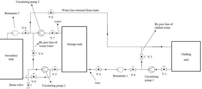
pumps, valves and pipes in addition to measuring instruments as illustrated in figure (1). The cylindrical storage tank is constructed of galvanised steel with 1.5 mm thickness, the test tank has dimensions of 40 cm diameter and 110 cm height, the nominal water depth is 100 cm, and the tank wall, bottom, and top are insulated on the outside with 5 cm thickness of fibreglass.
The refrigerating unit employed in the test system is an air-cooled refrigeration unit with 0.503 kW (0.15 ton) cooling capacity and operates with a reciprocating type compressor, which consumes 440 watts.
The secondary tank is a rectangular tank with 40 × 40 × 90 cm dimensions and contains 144 litters. It employed to receive the warm water from the storage tank and then departs to the refrigerating unit to recool again.
The test system includes three circulation water pumps; the first is located between the refrigerating unit and storage tank to pump the chilled water into a storage tank, the second is located between storage tank and secondary tank to withdraw the warm water through upper diffuser into the secondary tank, the third is used to return the water existed in a storage and secondary tanks into refrigerating unit to recool again
Two rotameters and 11 thermocouples are employed to measure the flow rates and temperatures. The first rotameter is located between the refrigerating unit and storage tank to measure the flow rate out of the refrigerating unit and supply it at a required level into the tank. The second rotameter is located between the storage
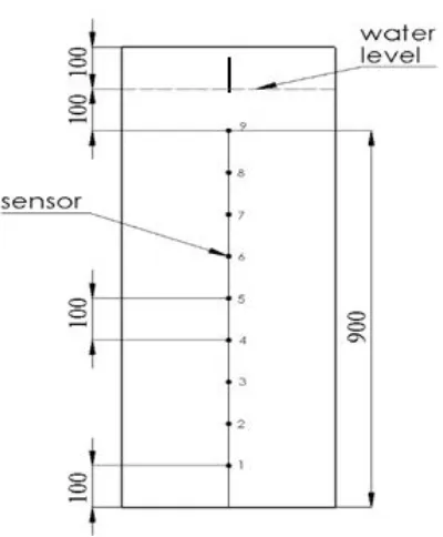
tank and secondary tank to measure the flow rate out of storage tank through upper diffuser only; the rotameter was calibrated with uncertainty ± 0.11 l/min. A storage tank is fitted with nine K-type thermocouples installed on the string located in the tank centre to measure the temperature changes across the tank height as shown in figure (2). The vertical spacing between thermocouples is 10 cm from the tank floor. The two other thermocouples are installed at the outlet line of the refrigerating unit and storage tank to measure the inlet and outlet temperatures, the thermocouples were calibrated with uncertainty ± 0.88℃. A temperature data recorder is employed to record the temperatures every 5-second interval of time.
[image:3.595.91.521.463.654.2]At first, the storage tank is filled with warm water at a temperature of 30℃ and the inlet chilled water temperature is approximately constant of 4.1℃ during the charging process. The flow rate supplied into a storage tank is varied from 1.5 to 7.5 l/min with an increment of 1 l/min. During the charging cycle, the chilled water charged at a certain level of the flow rate into the bottom of the storage tank through three inlet diffusers, 90-degree elbow diffuser, two-ring linear diffuser and two-ring radial diffuser. At the same time, the warm water leaves the top of the storage tank across the outlet pipe and circular diffusers into the secondary tank and continue until the tank is fully charged or reached steady temperature (final temperature). After the end of the charging process, the warm and chilled water are departed from storage and secondary tanks to refrigerating unit to recool again.
Figure 2. Distribution of temperature sensors across the tank height, all dimensions in mm
2.1. Description of the Inlet Diffuser
The performance of the storage tank depends primarily on the inlet diffuser. The tested flow rates are performed on a storage tank with three inlet diffusers, 90-degree elbow diffusers in which the elbow contains one opening with 19 mm diameter and 90° bending angle, it connected inlet pipe joined tank wall with 19 mm diameter, the inlet height between the opening and the tank floor is 2 cm as shown in figure (3). The inlet flow enters the tank as a vertical flow and impinges directly the tank floor.
Figure 3. Storage tank with 90-degree elbow diffuser, all dimensions in mm
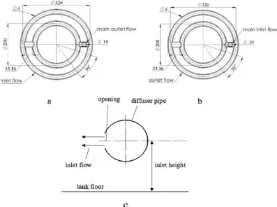
The two-ring circular diffuser consists of lower and upper diffusers in which the lower diffuser just installed above the tank floor with distance 1 cm inlet height (hi) as
the upper diffuser is installed below the free surface with distance 7 cm so as not to ingest the air with water, figure (4) depicted the location of the circular diffuser.
Figure 4. Locations of lower and upper two-ring circular diffuser in a storage tank, all dimensions in mm
Two-ring linear circular diffuser comprises of two pipes with 19 mm diameter, these pipes were twisted in the form large and small rings, the pipe ends were welded well, the two rings were connected with two segments of pipes to transfer the water into the large and small rings. The two circular pipes were perforated in the form holes with diameter of 6 mm, each circular pipe has ten openings distributed uniformly along the bottom and top of the pipe, the total area of the ten openings approximately equal to the area of the diffuser pipe, the face of the openings orients towards the tank floor for lower diffuser and orients towards the free surface for the upper diffuser. The flow exits the pipe through the openings of the lower diffuser as a vertical flow and impinged the tank floor directly and leaves the tank through the openings of the upper diffuser, figure (5) presents the description of the lower and upper two-ring linear diffusers.
[image:4.595.75.275.75.317.2] [image:4.595.341.489.160.370.2] [image:4.595.95.259.500.691.2]Figure 5. (a) Upper and (b) lower two-ring linear diffuser, (c) section of diffuser opening, all dimensions in mm
[image:5.595.102.501.90.390.2] [image:5.595.99.496.425.721.2]3. Performance Measures of Stratified
Chilled Water Storage Energy
Several measures are required to evaluate the performance of inlet diffusers equipped in the storage tank, these measures include:
3.1 Thermocline Thickness
Musser and Bahnfleth [14] defined thermocline thickness (ht) based on dimensionless cut-off temperature as per the following equation:
𝛩=𝑇(𝑦,𝑡)−𝑇𝑐
𝑇ℎ−𝑇𝑐 (1) Where: Θ is dimensionless temperature, T (y, t) is a measured temperature by the temperature sensor at a position during a time interval, ℃, Tc is cold water temperature or final temperature, ℃ and Th is warm water temperature or initial temperature, ℃
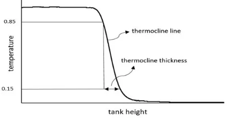
[image:6.595.66.288.434.550.2]During the charging cycle, the dimensionless temperature alters from a value of 1 at warm water temperature to a value of zero at final temperature. They defined cut-off points of dimensionless temperature to determine the thickness of the thermocline at various flow rates from 5% to 15%, the thermocline thickness in this study is limited from Θ= 0.15 to Θ= 0.85 and holds 70% of the overall temperature changes. Figure (7) shows the cut-off points on the temperature profile to determine the thermocline thickness.
Figure 7. thermocline thickness identified by dimensionless cut-off temperature versus tank height
3.2 Thermal Capacity
The thermal capacity is the quantity of heat removed from or added to a mass of storage medium as a result of an increase or decrease in temperature during a period of time.
Ct= ṁ c ∆T ∆t (2)
Where: 𝐶𝑡 is thermal capacity, kj, 𝑚̇ is mass flow rate,
kg/sec, c is specific heat, kj/kg. k, ∆T is a temperature difference, ℃ and ∆t is the time interval, second.
The thermal capacity of a storage medium stored in a one tank volume is:
𝐶𝑡=𝜌𝛢𝛨𝑐∆𝑇 (3)
Where: 𝜌 is water density, kg/m3, A is a tank area and H
is tank height, m.
There are three types of thermal capacity formed in a storage tank during the charging process:
3.2.1 Theoretical Capacity
The theoretical capacity is the maximum cooling capacity measured between initial and inlet water temperatures before taking place the mixing between incoming flow and tank water [15]. The maximum capacity can be calculated using the following equation:
𝐶𝑚𝑎𝑥=𝜌ΑΗ c (𝑇ℎ− 𝑇𝑖𝑛) (4)
Where: 𝐶𝑚𝑎𝑥 is the maximum capacity, kj and 𝑇𝑖𝑛 is
the average inlet temperature, ℃ 3.2.1 Integrated Capacity
Integrated capacity for one tank volume is the amount of energy that is stored in a storage tank after completing a cycle.
𝐶𝑖𝑛𝑡=𝜌ΑΗ𝑐�𝑇𝑖𝑛𝑖− 𝑇𝑓� (5)
Where 𝑇𝑓 is the average final temperature, ℃
3.2.3 Lost Capacity
Lost energy occurs in a region between the lower end of the thermocline, which lies on the inlet side of the cool region and a point located at the thermocline. Lost capacity can be defined mathematically as integration from the point where the temperature is equal to inlet temperature to the point at the thermocline where the temperature has limited value (Tlimit). For calculating the lost capacity of the
measured data, the integration must be converted into discrete summation as per the following equation [15]:
𝐶𝑙𝑜𝑠𝑡=∑ 𝑚̇𝑐 (𝑇 − 𝑇𝑖𝑛) ∆𝑡 (6)
Where: 𝐶𝑙𝑜𝑠𝑡 is the lost capacity, kjand 𝑇𝑖𝑛+𝜀<𝑇< 𝑇𝑙𝑖𝑚𝑖𝑡 where 𝜀 is an arbitrary small temperature tolerance
used to define the extent of the thermocline.
The lost capacity can be represented as the area between the average inlet and final temperatures or the lost stored energy between the inlet and final temperatures for one tank volume.
𝐶𝑙𝑜𝑠𝑡=𝜌ΑΗ𝑐�𝑇𝑓− 𝑇𝑖𝑛� (7)
Figure (8) illustrated the capacities measured in storage tank based on the temperature profile.
[image:6.595.306.530.591.729.2]Three measures of capacity can be combined in one equation for one tank volume:
𝐶𝑚𝑎𝑥=𝐶𝑖𝑛𝑡+𝐶𝑙𝑜𝑠𝑡 (8)
3.3 Half-cycle Figure of Merit
Trane et al. [6] defined a figure of merit as a ratio of integrated discharge capacity to the theoretical capacity during a complete cycle ( charge-discharge cycle). In spite of the difficulty of measuring a figure of merit during charging and discharging cycles, Musser and Bahnfleth [15] defined by analogy the half-cycle figure of merit as a ratio of the integrated capacity of charge or discharge cycle to the maximum capacity for one tank volume.
𝐹𝑂𝑀1�2=𝐶𝐶𝑖𝑛𝑡
𝑚𝑎𝑥|𝑜𝑛𝑒𝑡𝑎𝑛𝑘𝑣𝑜𝑙𝑢𝑚𝑒 (9) Where: 𝐹𝑂𝑀1
2
� is the half-cycle figure of merit.
Equation (9) can be simplified to become:
𝐹𝑂𝑀1�2=𝑇𝑇ℎ−𝑇𝑓
ℎ−𝑇𝑖𝑛 (10)
3.4. Equivalent Lost Tank Height
Musser and Bahnfelth[16] defined the equivalent lost tank height as a ratio of lost capacity to the maximum capacity per lost depth height of stored water, the equivalent lost tank height can be described the lost energy within a storage tank as a lost water depth or layer as a result of the mixing and heat transfer by convection and conduction.
𝐸𝐿𝐻= 𝐶𝑙𝑜𝑠𝑡
𝜌𝑐𝐴 (𝑇ℎ−𝑇𝑖𝑛) (11) Where ELHis equivalent lost tank height, m
4. Simulation Model
Three-dimensional, transient, laminar model of stratified chilled water storage tank is implemented using Ansys-Fluent 18.0 for predicting the vertical temperature distributions in a vertical storage tank equipped with three inlet diffusers. The computational domain is discretised into the mesh containing approximately 3680000 tetrahedral elements, the second-order upwind scheme is used to solve the discretisation equations and the time step for being simulation is set at 2 seconds. For tank model, the heat transfer from tank water to surroundings through the tank wall, bottom and top are neglected, the heat transfer by convection from the wall into water is also neglected and the heat transfer by conduction through the wall is ignored.
5. Results and Discussion
5.1 Test results for Temperature Distributions
The degree of mixing can be revealed using temperature
distributions within a storage tank, the temperature data obtained from temperature sensors can be presented as a dimensionless temperature (Θ) versus dimensionless height (Z) for different flow rates during charging cycle.
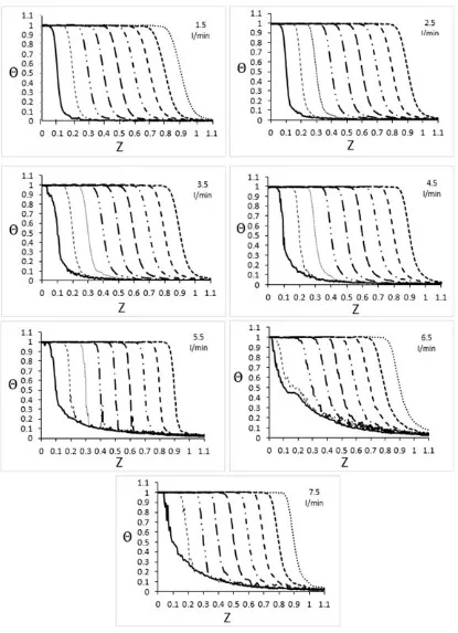
The preliminary results of temperature distributions within a storage tank with elbow diffuser are provided in figure (9). It is observed that the intensity of mixing within the range 1.5-4.5 l/min is little while the intensity of mixing within the range 5.5-7.5 l/min is vigorous because the flow velocity within the range 1.5-4.5 l/min is lower whereas the flow velocity within the range 5.5-7.5 l/min is higher. In addition, as shown in the figure, the mixing intensity can be defined by the tails on the inlet side of the thermocline, it is observed that the tails within the range 1.5-4.5 l/min remain at the same level as the tails within the range 5.5-7.5 l/min displace upward especially at the beginning of the charging process. This indicates that the mixing is very intensive within this range. So, the tests performed indicated that the stratification is good at flow rates from 1.5-4.5 l/min and after that, the stratification is deteriorated to worse at flow rates from 5.5-7.5 l/min.
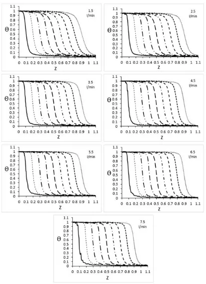
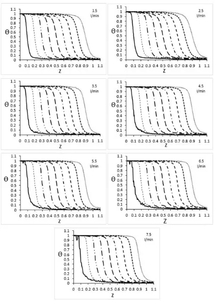
Figure (10) provides the temperature distributions at the vertical positions within the storage tank with a two-ring linear diffuser. It is observed that the mixing intensity for all flow rates is very little because the diffuser employed contains two rings, which accommodate greater amount of flow in addition to the pipe rings is perforated evenly along the pipe length which covers the plan area and permits to enter the flow into the tank with small jets and therefore merges with ambient water gently without turbulent waves. Figure (11) provides temperature distribution obtained from storage tank with a two-ring radial diffuser, it is observed that the mixing intensity is little for flow rates from 1.5-5.5 l/min then increases slightly for flow rates 6.5 and 7.5 l/min such that the radial diffuser is similar to linear diffuser except for the flow direction, the main reason is that physically, the thermal stratification depends primarily on density current in which the density current must be impinged and travelled along the tank floor to form after pass of time a steep thermocline, from this concept, the inlet flow leaving the openings of the linear diffuser impinges directly the tank floor as the inlet flow out of openings of radial diffuser is impinges directly the tank water causing increase in intense mixing.
It is worth noting that during the tests, the temperature below the thermocline for the linear diffuser is falling rapidly as the temperature for elbow and radial diffusers is falling slowly, this indicates that the linear diffuser produced the least mixing and the radial diffuser produced less mixing while the elbow diffuser produced most mixing.
5.2 Test Results for Thermal Performance
and equivalent lost tank height are shown in tables (1), (2) and (3) respectively. For thermocline thickness, the data is taken at 30 cm height far from the tank floor. It is noted that the thermocline for elbow diffuser produced higher
thickness at 1.5 l/min and declined slightly to 3.5 l/min then rises to 4.5 l/min, after that the thermocline thickness fluctuated from 5.5 to 7.5 l/min because of the inertia of incoming flow as well as non-uniformity of flow over
[image:8.595.89.504.139.712.2]The tank floor. For linear diffusers, it is noted that the thickness of the thermocline is thick at 1.5 l/min and then declined to 7.5 l/min such that the flow rate of 1.5 l/min is much better than remaining flow rates in terms of degree of mixing, the reason for this is probably due to the non-uniform pressure drop along the diffuser pipe, in other words, the flow enters into the tank across a few openings not all due to the small amount of flow entering into diffuser whereas it is found that the thermocline thickness is thinnest at flow rate of 6.5 or 7.5 l/min because the flow is left all openings, in addition, the flow covers the tank floor uniformly. For the radial diffuser, the thermocline thickness initiates to decline to 3.5 l/min then rises to 7.5 l/min, the reason is known and mentioned previously that the flow leaving the diffuser through the openings collides with tank water immediately which causes disturbances during the mixing but at the same time the inlet flow is covered the tank floor uniformly also, in contrast, the inlet flow for elbow diffuser collides the tank floor with non-uniform distribution over the tank floor causing more losses. As a result, the linear diffuser achieves smaller thermocline thickness than radial diffuser by 10.6% and elbow diffuser by 31.1%.
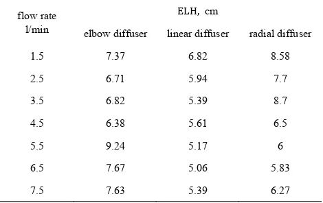
[image:11.595.304.539.100.260.2]The results for half-cycle figure of merit demonstrate that the half-cycle figure of merit of the three inlet diffusers exceeds 90% indicating that the tank is stratified satisfactorily, the results for equivalent lost tank height indicate that the lost or unusable depth of stored water in a storage tank is the least using linear diffuser, lost depth is less using radial diffuser and higher using elbow diffuser, based on the equations (1) and (12), it should be noted that the 𝐹𝑂𝑀½ and the 𝐸𝐿𝐻 depends primarily on final temperature, when the final temperature decreases or close to inlet temperature, the 𝐹𝑂𝑀½ increases and 𝐸𝐿𝐻 deceases, as a result, the linear diffuser attains lower final temperature than elbow and radial diffuser, therefore, it may be stated that the storage tank with a linear diffuser for𝐹𝑂𝑀½ improves the thermal performance more than elbow and radial diffusers by 1.7 and 1.4% respectively and reduces the lost layer smaller than radial diffuser by 20.6% and elbow diffuser by 24%.
Table 1. measurements of thermocline thickness taken at height 30 cm away from the tank floor for the elbow, linear and radial diffusers
flow rate l/min
thermocline thickness, cm
elbow diffuser linear diffuser radial diffuser
1.5 7.39 9.56 8.66
2.5 6.76 7.69 7.7
3.5 6.79 6.71 7.06
4.5 7.33 6.34 7.4
5.5 3.53 6.11 7.41
6.5 29.56 5.99 7.91
7.5 9.03 6.1 8.12
Table 2 measurements of the half-cycle figure of merit at different flow rates for elbow, linear and radial diffusers
flow rate l/min
FOM1�2, %
elbow diffuser linear diffuser radial diffuser
1.5 93.3 93.8 92.2
2.5 93.9 94.6 93
3.5 93.8 95.1 92.1
4.5 94.2 94.9 94.1
5.5 91.9 95.3 94.5
6.5 93 95.4 94.7
7.5 93 95.1 94.3
Table 3. measurements of equivalent lost tank height at different flow rates for elbow, linear and radial diffusers
flow rate l/min
ELH, cm
elbow diffuser linear diffuser radial diffuser
1.5 7.37 6.82 8.58
2.5 6.71 5.94 7.7
3.5 6.82 5.39 8.7
4.5 6.38 5.61 6.5
5.5 9.24 5.17 6
6.5 7.67 5.06 5.83
7.5 7.63 5.39 6.27
5.3. Validation Results
[image:11.595.304.539.289.437.2] [image:11.595.58.287.605.754.2]a
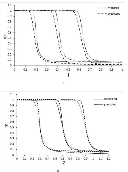
[image:12.595.314.524.78.363.2]Figure 12. predicted and measured temperature profiles versus dimensionless time and tank height in stratified storage tank equipped with an elbow inlet diffuser at different heights for a flow rate of 4.5 l/min.
[image:12.595.67.282.418.715.2]Figure 13. predicted and measured temperature profiles versus dimensionless time and tank height in stratified storage tank equipped with a linear inlet diffuser at different heights for a flow rate of 6.5 l/min.
Figure 14. predicted and measured temperature profiles versus dimensionless time and tank height in stratified storage tank equipped with a radial inlet diffuser at different heights for a flow rate of 6.5 l/min.
6. Conclusions
Experiments of various charging flow rates have been conducted in a small-scale stratified chilled water storage tank equipped with three inlet diffusers, elbow, two-ring linear circular diffuser and two-ring radial circular diffuser. The test results are dependent on temperature distribution, which reveals the degree of stratification and performance metrics that determine the thermal performance of a stratified tank. Several conclusions can be drawn from the study findings:
The mixing has a first-order effect on deterioration of stratification especially thermocline as a result of the high velocity of the incoming flow, the low-velocity incoming flow will mix with tank water gently without occurring disturbances and therefore results in reducing thermocline size, correspondingly, the high-velocity incoming flow will mix with tank water vigorously which causes disturbances below thermocline and therefore leads to an increase in thermocline size, so, the mixing intensity is proportional to velocity of incoming flow, accordingly, the storage tank with two-ring circular diffuser reduces turbulent mixing significantly compared with the elbow diffuser that improves the turbulent mixing.
also on diffuser design, the diffuser containing multiple rings, the position of the opening and equal pressure drop, these parameters contribute to minimising the thermocline thickness. As a result, diffuser design must be taken into consideration because it is responsible for enhancement or deterioration of stratification and in consequence the linear diffuser with two rings and openings placed below the pipes and distributed uniformly produced thermocline thickness less than remaining diffusers.
Performance measures including the half-cycle figure of merit and equivalent lost tank height have a significant effect in determining the quality of stratification, thermal performance indicated by them using linear diffuser produced a good performance and satisfactory stratification compared with elbow and radial diffusers.
REFERENCES
[1] M. Karim, "Performance evaluation of a stratified chilled-water thermal storage system," World Academy of Science, Engineering and Technology, vol. 53, pp. 326-334, 2009.
[2] S. Hasnain, "Review on sustainable thermal energy storage technologies, Part II: cool thermal storage," Energy conversion and management, vol. 39, pp. 1139-1153, 1998. [3] C. E. Dorgan and J. S. Elleson, Design guide for cool
thermal storage: ASHRAE Atlanta, 1993.
[4] M. Wildin and C. Truman, "A summary of experience with stratified chilled water tanks," ASHRAE transactions, vol. 91, pp. 956-976, 1985.
[5] J. Yoo, M. Wildin, and C. Truman, "Initial formation of a thermocline in stratified thermal storage tanks," ASHRAE Trans.;(United States), vol. 92, 1986.
[6] N. Tran, J. Kreider, and P. Brothers, "Field measurement of chilled water storage thermal performance," ASHRAE transactions, vol. 95, pp. 1106-1112, 1989.
[7] M. Wildin and C. Truman, "Performance of Stratified Vertical Cylindrical Thermal Storage Tanks, Part I: Scale Model Tank " ASHRAE Transacations, vol. 95, pp. 1086-1095, 1989.
[8] M. Wildin, "Performance of stratified vertical cylindrical thermal storage tanks. II: Prototype tank," ASHRAE transactions, vol. 95, pp. 1096-1105, 1989.
[9] M. W. Wildin, "Experimental results from single-pipe diffusers for stratified thermal energy storage," American Society of Heating, Refrigerating and Air-Conditioning Engineers, Inc., Atlanta, GA (United States) 0001-2505, 1996.
[10] W. Bahnfleth and A. Musser, "Case Study of Stratified Chilled Water Storage Utilization for Comfort and Process Cooling in a Hot, Humid Climate," 1998.
[11] W. P. Bahnfleth and J. Song, "Constant flow rate charging characteristics of a full-scale stratified chilled water storage tank with double-ring slotted pipe diffusers," Applied thermal engineering, vol. 25, pp. 3067-3082, 2005. [12] M. Karim, "Experimental investigation of a stratified
chilled-water thermal storage system," Applied Thermal Engineering, vol. 31, pp. 1853-1860, 2011.
[13] S. Li, Y. Li, X. Zhang, and C. Wen, "Experimental study on the discharging performance of solar storage tanks with different inlet structures," International Journal of Low-Carbon Technologies, vol. 8, pp. 203-209, 2012. [14] A. Musser and W. P. Bahnfleth, "Evolution of temperature
distributions in a full-scale stratified chilled-water storage tank with radial diffusers," ASHRAE Transactions, vol. 104, p. 55, 1998.
[15] W. P. Bahnfleth and A. Musser, "Thermal performance of a full-scale stratified chilled-water thermal storage tank,"
ASHRAE transactions, vol. 104, p. 377, 1998.