© 2018, IRJET | Impact Factor value: 6.171 | ISO 9001:2008 Certified Journal | Page 310
EXPERIMENTAL STUDY ON BUCKLING BEHAVIOUR OF COLD-FORMED
STEEL SECTIONS
P.Vijayaragunath
1, S.Vimal
2, T.Vinitha
3, T.V.Prathib
4, S.Sureshbabu
51,2,3,4
UG Students, Department of Civil Engineering, Valliammai Engineering College,
Kanchipuram, Tamilnadu, India.
5
Assistant professor, Department of Civil Engineering, Valliammai Engineering College,
Kanchipuram, Tamilnadu, India.
---***---Abstract-
Cold-formed steel is also called as light gaugesteel sections. CFS section is widely used structural elements in India. One of the great advantages of cold-formed steel (CFS) is the immense flexibility that the material affords in forming cross-section. Whereas, the low strength-to-weight ratio of hot rolled steel members leads to increase in overall load on structure as compared with cold-formed steel sections which having high strength-to-weight ratio. This paper presents a study of compressive behavior of cold formed steel (CFS) 1.Back to back lipped channel section without gap, 2.Face to face lipped channel section with gap. The length of the column is kept constant for 1m. Experimental setup will be made to find the load versus deflection and load versus strain behavior under compression. Research project aims to provide which section is economical, more load carrying capacity and lesser deflection.
Key words: cold-formed steel, buckling behavior, compression, load carrying capacity.
1.
INTRODUCTION
Cold-formed steel (CFS) or light gauge is a type of steel created by cold forming process. Cold-formed steel goods are bring into existence by the working of sheets steel using stamping, rolling or presses to deform the sheets into a usable product. The thickness of the sheet used is generally between 1 mm to 8 mm. Even though cold-formed steel sections finds its application in transmission poles, transmission towers, grain bins, storage racks, car bodies, railway coaches and various types of equipment , but in building construction it has limited advancement. The use of hot rolled steel sections becomes uneconomical for the steel structures subjected to light and moderate loads. The structural members such as purlins, grits, roof trusses, complete framing of one and two storey residential, commercial and industrial structure subjected to moderate load, for which cold-formed steel members may be agreeable. Cold-formed sections such as zee section, channel section, I-sections, angles, Hat sections, T-section, and tubular members are commonly used.
The yield strength of steel sheets is at least 280 N/mm2, which is used in cold-formed steel sections. Although there is a trend to use steels of higher strengths and sometimes as low as 230 N/mm2. The ratio of tensile strength to yield strength for light gauge steel commonly ranges from 1.2 to 1.8.
Cold-formed steel are available for use as basic building elements for assembly at site or as prefabricated frames or panels. These thin steel sections are cold-formed, i.e. their building process incorporates into steel sections in a cold state (i.e. without supply of heat) from steel sheets of uniform thickness. Sometimes they are also called light gauge steel sections or cold rolled steel sections. Cold-formed steel sections are normally manufactured by either roll forming or press braking. The process used is largely dependent on the complexity of the section geometry, and the volume of the particular section required. Past research investigated on compressive behavior of build-up cold formed steel sections and found out that the compression capacity was more than the single cold formed steel section. Hence cold formed built up sections were used in these research.
© 2018, IRJET | Impact Factor value: 6.171 | ISO 9001:2008 Certified Journal | Page 311
3. SPECIMEN DETAILS
3.1 BACK TO BACK CHANNEL SECTION
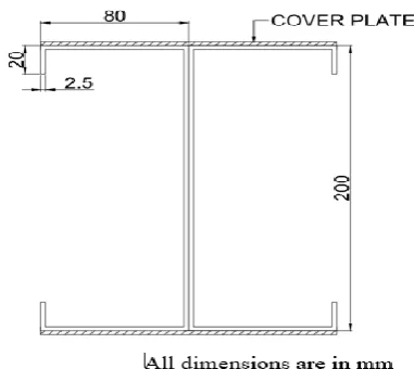
[image:2.595.319.549.102.214.2]A.CROSS-SECTION OF THE SPECIMEN:
TABLE 1: DETAILS OF THE SPECIMEN (BACK TO BACK)
Column section L*B*D*LIPS
Depth, d (mm) 200
Width, b (mm) 80
Lips, (mm) 20
Thickness of cover
plate 2.5
Length of column
(mm) 1000
3.2 FACE TO FACE CHANNEL SECTION B. CROSS SECTION OF THE SPECIMEN:
TABLE 2: DETAILS OF THE SPECIMEN (FACE TO FACE)
Column specimen L*B*D*LIPS
Depth, d (mm) 200
Width, b (mm) 80
Lips, mm 20
Thickness of cover plate 2.5 Length of column (mm) 1000
4. EXPERIMENTAL INVESTIGATION
[image:2.595.63.254.152.322.2]The specimens are fabricated by locally available cold-formed steel sheets. The CFS sheets of 2.5mm for channels and for connecting plates. The channels are connected by means of weld. The entire fabricated specimen of back to back and face to face are shown below.
FIG 1: FABRICATED BACK TO BACK SPECIMEN
[image:2.595.348.515.338.521.2]© 2018, IRJET | Impact Factor value: 6.171 | ISO 9001:2008 Certified Journal | Page 312
5. EXPERIMENTAL SET-UP
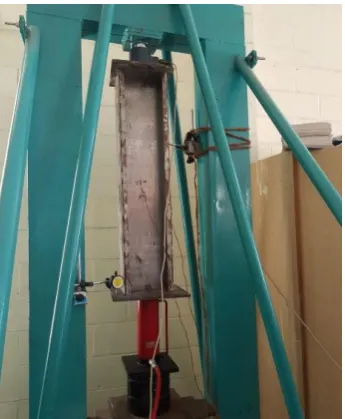
[image:3.595.324.552.247.394.2]Cold-formed build up channel sections of 1000 mm length and 200 mm depth is tested in a loading frame of capacity 400KN under axial loading condition for both back to back and face to face channel specimens. Fixed support is provided at the ends of specimen. LVDT and load cell are used for measuring deflection and load increment. All data were recorded in a data acquisition system .Strain gauge were fixed at the top flange and middle web portion and were connected to a data logger from which the readings were noted at every load interval until failure of the column. The experimental set-up for the test specimen were shown below.
[image:3.595.68.552.249.775.2]FIG 3: EXPERIMENTAL SETUP FOR BACK TO BACK SPECIMEN
FIG 4: EXPERIMENTAL SET-UP FOR FACE TO FACE SPECIMEN
6. EXPERIMENTAL RESULTS
6.1 LOAD VERSUS DEFLECTION CURVE
The experimental load-deflection curves of the cold-formed steel column of specimen back to back and face to face is shown in fig 5&6. Back to back specimen failed at on ultimate load of 155KN with central deflection of 3.80mm face to face specimen failed at an ultimate load of 100KN with central deflection of 5.19mm.
[image:3.595.76.249.286.496.2]FIG 5: GRAPH FOR LOAD VS DEFLECTION (BACK TO BACK SPECIMEN
FIG 6: GRAPH FOR LOAD VS DEFLECTION (FACE TO FACE SPECIMEN)
FIG 7: GRAPH FOR LOAD VS STRAIN (BACK TO BACK SPECIMEN)
6.2 LOADS VERSUS STRAIN CURVE
[image:3.595.320.554.462.627.2]© 2018, IRJET | Impact Factor value: 6.171 | ISO 9001:2008 Certified Journal | Page 313 FIG 7. A) AT WEB (MIDDLE)
[image:4.595.48.522.77.805.2]FIG 7. B). AT FLANGE (TOP)
FIG 8: GRAPH FOR LOAD VS STRAIN (FACE TO FACE SPECIMEN)
FIG 8. A) AT WEB (MIDDLE)
FIG 8. B) AT FLANGE (TOP)
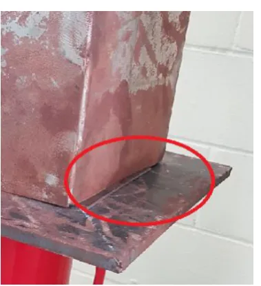
[image:4.595.42.277.111.492.2]6.3 FAILURE PATTERN
FIG 9: FAILURE OCCUR AT THE TOP OF BACK TO BACK SPECIMEN
[image:4.595.312.542.143.317.2] [image:4.595.47.276.299.497.2] [image:4.595.343.523.374.556.2]© 2018, IRJET | Impact Factor value: 6.171 | ISO 9001:2008 Certified Journal | Page 314 6.4 ANALYSIS OF SPECIMENS
[image:5.595.69.259.71.279.2]Experimental analysis have been carried out between back to back lipped channel section and face to face lipped channel section
TABLE 3: EXPERIMENTAL ANALYSIS
SPECIMEN BACK TO BACK FACE TO FACE \MAXIMUM
LOAD (KN) 155 150
DEFLECTION
(mm) 3.80 5.19
STRAIN 246.7 73
7. CONCLUSIONS
Experimental investigation were carried out to make a comparative study on the compressive behavior of back to back channel section with lip and face to face channel section without lip.
1. The cover plate at the specimen increases the load carrying capacity of the column.
2. The ultimate deflection of the cold-formed back to back section with lip was 3.80mm and for face to face section with lip was 5.19mm.
3. By comparing both the sections we came to know that the section with lip has high load carrying capacity
ACKNOWLEDGEMENT
We express our deep sense of gratitude to Dr.Elango, M.E., Ph.D. F.I.E, Professor and Head, Department of Civil Engineering for the valuable support, facilities and help in shaping this project into a successful one. We are especially indebted to our guide Mr.S.SURESH BABU M.E.,
Assistant Professor (O.G) for his valuable guidance, ideas and continuous encouragement for the successful completion of this project. We extend our sense of gratitude and thanks to our PARENTS, classmates and friends for their supports for the successful completion of this project.
REFERENCES
(1) Anna Green Antony et al, “Cold Formed Steel Sigma Section Joints” IJIRT, Volume 3, Issue 4, (September 2016).
(2) W.Reza, S.Senthil selvan et al, “Experimental Study on Flexural Behavior of Cold Formed Steel Channel and I Sections Providing Angle Stiffener on the Web”, IJST, Volume 9, (September-2016).
(3) S.Pradeepa, N.R. Monika et al, “Flexural Behavior of Cold Formed Sigma and Z- Purlin” IJOTER, Volume 4, Issue (1), (January – June 2016).
(4) Kumaran V, Sureshbabu S, “Experimental study on flexural behavior of light gauge steel section” IJSRD, volume 4, Issue 01,2016.
[5] Kitipornchai, S., and Trahair, N.S. (1972). Elastic stability of tapered I-beams. Journal of structure Div., ASCE, Vol 98(3), 713-728.
[6] John C. Ermopoulos (1986).Buckling of Tapered Bars under Stepped Axial Loads. Journal of Structural Engineering, ASCE, Volll2(6), 1346-1354.