© 2017, IRJET | Impact Factor value: 5.181 | ISO 9001:2008 Certified Journal | Page 1680
Influence of Cutting Fluid Condition and Cutting Parameter on Material
Removal Rate in Straight Turning Process of En31 Steel
Karan A. Katle
1, Abhishek Rehpade
2, Faruk Qureshi
31
B.E. (Mechanical Engineering), JD College of Engineering and Management, RTM Nagpur University,
Maharashtra, India
2
B.E. (Mechanical Engineering), JD College of Engineering and Management, RTM Nagpur University,
Maharashtra, India
3
B.E. (Mechanical Engineering), JD College of Engineering and Management, RTM Nagpur University,
Maharashtra, India
---***---Abstract -
In machining process in order to achieve highproductivity, high values of machining parameters are needed resulting in generation of high temperature zones at tool chip interface. In a machining process, high values of machining parameters directly affects material removal rate. Also the generation of high temperature zones at tool chip interface will have an adverse effect on production quality such as poor surface finish, reduction in tool life, etc. The present paper deals with the study of effects of different cutting parameters on material removal rate in straight turning process of En31 steel under different environmental conditions.
Key Words: MQL, EN-31, Material Removal Rate, Cutting
fluid, Metal cutting, Machining, Carbide Cutting Tool, Wet Machining, Taguchi method.
1. INTRODUCTION
Machining is a process of removal of material from a workpiece in order to obtain a product of desired shape. In order to meet the demand of higher productivity, emphasize should be given on development of machining process accordingly. Productivity could be increase by using specific method of production, efforts for reducing cost of production, better surface finish, etc. One of the important factors of increasing productivity is high rate machining parameters. The high rates of machining parameters result in high material removal rates. So, one can directly say high material removal rate results in high productivity.
The high material removal rate also results in friction as well as generation of high temperature zones at tool chip interface. The generation of high temperature zones results in poor surface finish, softening of tool material due to which tool wears out at a faster rate resulting in reduction in tool life. Use of appropriate cutting fluid during machining may help to eliminate such problem. It was found that using cutting fluid during machining operation results in reduction in generation of high temperature zones, followed by good surface finish as well as less tool wear.
Lubrication not only offers cooling of high temperature zones, in addition to this, they also provide sufficient time for
tool and workpiece to get cool down and maintain them at ambient conditions ensuring reduction in error of size caused due to thermal expansion of workpiece, preventing dimensional transformation and maintaining good surface finish as well as dimensional accuracy.
As each advantage has a disadvantage too, conventional used of cutting fluids were found to be hazardous for humans as well as environment resulting in skin infections followed by various types of diseases. Also introducing large amount of cutting fluid at tool chip interface resulting in bounce back of the major part of cutting fluid from the external surface and thus proper cooling of tool chip interface cannot be ensured. It is estimated that the cost of cutting fluid is 7%-17% range of total cost in industry. Thus increased rate of cutting fluid will adversely affect the working capital of the industry. So an alternative is needed for which can serve the purpose of cutting fluid applied in flooded condition.
© 2017, IRJET | Impact Factor value: 5.181 | ISO 9001:2008 Certified Journal | Page 1681
2. MINIMUM QUANTITY LUBRICATION
Minimum Quantity Lubrication also termed as semi dry lubrication or micro lubrication is a technique suggesting usage of cutting fluid in the range of 50-300 ml per hour. MQL combines functionality of cooling lubrication technique with the consumption of extremely less amount of cutting fluid. There are 3 types of MQL technique. First one is Low pressure spray systems: These systems have the flow rate around 0.5 to 10 l/hr. In this cooling technique, lubricant is transmitted to the machining surface by drawing it in air current. Another system uses dosing pumps delivering defined quantity of cooling lubricant to the machining surface without air. The flow rates are adjusted to 0.1 to 10 ml/cycle with up to 260 cycle/min. The third and most widely used pressure systems includes transportation of lubricant to the nozzle by pump through the spate supply pipe where it is mixed with compressed air at certain pressure resulting in formation of mist form of lubricant. The flow rates here are about 50-300 ml/hr. In this one can adjust the quantities of air and lubricant separately.
3. WORKING PRINCIPLE
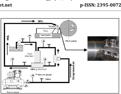
[image:2.595.307.558.61.255.2]High cutting zone temperature is generally tried to be controlled by employing flood cooling by soluble oil. In high speed–feed machining, conventional cutting fluid application fails to penetrate the chip-tool interface and thus cannot remove heat effectively and the use of cutting fluid has become more problematic in terms of both employee health and environmental pollution. Addition of extreme pressure additives in the cutting fluids does not ensure penetration of coolant at the chip–tool interface to provide lubrication and cooling. Minimum quantity lubrication (MQL) is based on the principle that a drop of liquid is split by an air flow, distributed in streaks and transported in the direction of flow of air. MQL consists of a mixture of pressurized air and oil micro- droplets applied directly into the interface between the tool and chips. MQL decreased the contact length compared to dry cutting for both short and long engagement time. However, high-pressure jet of lubricant, when applied at the chip–tool interface, could reduce cutting temperature and improve tool life to some extent. The schematic diagram of MQL working principal is shown below:
Fig. 1: Working Principle of MQL
In the mixing chamber of the setup, compressed air at about pressure 5bar is the inlet of the mixing chamber where lubricant is admitted due to creation of vacuum by admission of high pressure gas. An air ejector in the mixing chamber plays a vital role as it atomizes the mixture of air and lubricant into fine mist form known as aerosol. This aerosol is directly introduced at tool chip interface out of the mixing chamber through the nozzle. Minimum Quantity Lubrication also termed as semi dry lubrication or micro lubrication is a technique suggesting usage of cutting fluid in the range of 50-300 ml per hour. MQL combines functionality of cooling lubrication technique with the consumption of extremely less amount of cutting fluid. There are 3 types of MQL technique. First one is Low pressure spray systems: These systems have the flow rate around 0.5 to 10 l/hr. In this cooling, lubricant is transmitted to the machining surface by drawing it in air current. Another system uses dosing pumps delivering defined quantity of cooling lubricant to the machining surface without air. The flow rates are adjusted to 0.1 to 10 ml/cycle with up to 260 cycle/min. The third and most widely used pressure systems includes transportation of lubricant to the nozzle by pump through the spate supply pipe where it is mixed with compressed air at certain pressure resulting in formation of mist form of lubricant. The flow rates here are about 50-300 ml/hr. In this one can adjust the quantities of air and lubricant separately.
4. CUTTING FLUID
© 2017, IRJET | Impact Factor value: 5.181 | ISO 9001:2008 Certified Journal | Page 1682 Therefore, it is essential to reduce this cost to save both
money and work environment.
32 Ns/m2 along with viscosity index as 95. The Lubricants are manufactured from selected base oil which changes less in terms of viscosity with temperature. These oils are fortified with additives to offer long services, however during their selection care must be taken to ensure none clogging of sintered bush bearing.
5. TAGUCHI METHOD
Taguchi develop a special design of orthogonal array to study the entire parameters with small number of experiment only. Taguchi method is used for design of high quality system. It optimizes the performance characteristics by setting down of design parameters and reducing sensitivity of system performance to variation source. The optimization of parameter is to be done in 3 steps, i.e., system design, parameter as well as tolerance design. In system design, in order to produce a functional
design, engineer has to apply scientific and engineering knowledge. It involves design of process and product. In parameter design, the process parameter values are
optimized for improving quality characteristics and to identify product parameter value under optimum process parameter values.
Tolerance design is a method to fine tune the parameter design results by tightening the factors tolerances having the significant influence on products. Thus, this identifies the need of innovation and better materials, parts, machinery, etc.
In case of parameter design for Taguchi method, following steps are involved:
1. Identification of quality characteristics and selecting design parameters.
2. Determining no. of levels for design parameters 3. Selection of a proper orthogonal array and assignment
of design parameters to orthogonal array
4. Carrying out experiments based on orthogonal array 5. Analysis of experimental results using S/N ratio 6. Selection of optimal level of design parameters 7. Verification through confirmation experiment.
Taguchi Method recommends using signal-to-noise ratio, where signal is the required entity and noise is unnecessary entity. There are 3 modules of quality characteristics in analysis of S/N ratio: Lower the better, Higher the better and Nominal the best. The optimal level of process parameters is levelled with greatest S/N ratio.
Formulas for calculation of S/N ratio are:
Nominal is the best: S/NT = 2)
Larger is the best (max.): S/NL = -10 log (1/n i2)
Smaller is best (min.): S/NS = -10 log (1/n i2)
Where, = Average of observed data,
2 = Variance of y,
n = No. of observations y = Observed data
The S/N ratio is to be calculated in decibel units. Here, larger is the better modules are selected, as the desired output parameter of a machining process of larger material removal rate and good surface finish.
6. EPERIMENTAL WORK
The experiment is carried out by turning En31 steel of 25mm dia. and 100 mm length on a CNC lathe machine under different cutting environments namely dry, flood and MQL, using various cutting speed-feed combinations. The cutting parameters selected are cutting speed, depth of cut and feed rate. The composition of En31material is tested by using spectrometer. The experiment is carried out on a basis of L9 orthogonal array which suggests that, total 9 experiments were to be carried out per cutting environment.
L9 orthogonal array have following benefits:
1. Conclusions valid over the entire region spanned by the control factors and their settings.
2. Large saving in the experimental effort. 3. Analysis is easy
The cutting tool used in this research is CVD coated carbide TiC+AI2O3+TiN insert. The type of inserts is DNMG 110408E-TM.
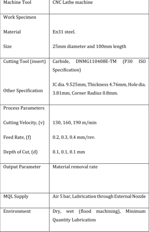
© 2017, IRJET | Impact Factor value: 5.181 | ISO 9001:2008 Certified Journal | Page 1683 Table -1: Experimental Condition
Table -2: Process Parameters
7. MATERIAL REMOVAL RATE
The material removal rate is the volume of material removed per unit time in mm3/sec.
Theoretically,
Material Removal Rate MRR =
Where, v = cutting speed m/min f = feed rate mm/rev d = depth of cut (mm)
[image:4.595.308.562.337.551.2]Analytically, The MRR is calculated by using above formulae for each combination of L9 OA. Three different cutting parameters are available and in order to achieve reliable results from the statistical analysis, three repeated tests are conducted for each trial. Therefore, total 9 experiments are carried out using L9 OA. Also, in all environmental conditions, no change is to be done in cutting speed, feed rate and depth of cut, and cutting parameters is going to be vary in the similar way (i.e., same L9 OA is used), therefore, MRR will remain same for dry, flood as well as MQL cutting condition.
Table -3: Experimental Result for MRR
Sr. No. Cutting Speed Feed Depth of Cut MRR
1 1 1 1 43.33
2 1 2 2 65.00
3 1 3 3 86.66
4 2 1 2 80.00
5 2 2 3 106.66
6 2 3 1 53.33
7 3 1 3 126.66
8 3 2 1 63.33
9 3 3 2 95.00
In order to check the material removal rate experimentally, at the end of experiment, following formulae is used:
Experimentally,
MRR=
8. ANALYSIS OF DATA
The transformations of the repeated data in a trial into a single consolidate value is suggested by Taguchi method, and are called as S/N ratio. In the Taguchi method, the term ‘ ’ ( ) ‘ ’ undesirable value (S.D.) for the output characteristic. So the S/N ratio represents the amount of variation present in the
Machine Tool CNC Lathe machine
Work Specimen
Material
Size
En31 steel.
25mm diameter and 100mm length
Cutting Tool (insert)
Other Specification
Carbide, DNMG110408E-TM (P30 ISO Specification)
IC dia. 9.525mm, Thickness 4.76mm, Hole dia. 3.81mm, Corner Radius 0.8mm.
Process Parameters
Cutting Velocity, (v)
Feed Rate, (f)
Depth of Cut, (d)
130, 160, 190 m/min
0.2, 0.3, 0.4 mm/rev.
0.1, 0.1, 0.1 mm
Output Parameter Material removal rate
MQL Supply Air 5 bar, Lubrication through External Nozzle
Environment Dry, wet (flood machining), Minimum
Quantity Lubrication
Factor Code Level 1 Level 2 Level 3 Unit
Cutting Speed
A 130 160 190 m/min.
Feed B 0.2 0.3 0.4 mm/rev.
Depth of Cut
© 2017, IRJET | Impact Factor value: 5.181 | ISO 9001:2008 Certified Journal | Page 1684 quality characteristic. Thus S/N ratio is the measure of
deviation of quality characteristic from the desired value. As stated earlier, three modules of S/N ratio are available, lower the better, nominal the better, higher the better, the higher the better module is going to be used. This is in accordance to the output parameter i.e., surface finish and material removal rate which must be higher.
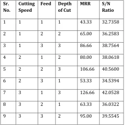
Table -4: Experimental result of MRR and S/N Ratio
Sr. No.
Cutting Speed
Feed Depth of Cut
MRR S/N
Ratio
1 1 1 1 43.33 32.7358
2 1 2 2 65.00 36.2583
3 1 3 3 86.66 38.7564
4 2 1 2 80.00 38.0618
5 2 2 3 106.66 40.5600
6 2 3 1 53.33 34.5394
7 3 1 3 126.66 42.0528
8 3 2 1 63.33 36.0322
9 3 3 2 95.00 39.5545
The L9 OA is repeated for dry, flood as well as MQL machining. It was observed that as cutting parameters is not changed in dry, flood as well as MQL machining, same L9 OA is obtained.
The response table as well as response graph for Signal to noise ratio from Taguchi analysis is generated for MRR. Fig. 4 shows the S/N response graph for MRR ratio. The greater S/N ratio corresponds to more favorable effect of input variable on the output. The larger the better module is selected as larger will be the material removal rate, larger will be the production rate and hence, production efficiency increases
.
[image:5.595.307.558.146.343.2]Table -5: Response table for signal to noise ratio
Fig -1: Mean S/N Ratio graph for MRR.
9. RESULT AND DISCUSSION
From the data collected by taguchi method, it is found that the optimum level for high MRR for speed is level 3 (190 m/min.), for feed is level 1 (0.2mm/rev.) and depth of cut is level 3 (0.1 mm) (from Table -4, Larger the better module). Experimentally, it was found that MRR is same for all cutting environment condition. As cutting speed, feed rate and depth of cut is not going to be changed at each cutting environmental condition, same results for MRR in each cutting fluid is obtained. Thus it can be seen that cutting fluid or cutting environmental condition will not have an effect on material removal rate.
Material removal rate is highly influenced by cutting parameter. The data collected in the Taguchi method are summarized in Table -5 and Fig. -1 which are obtained from Minitab software, it can be seen that for MRR, the most significant factor is depth of cut followed by cutting speed and feed rate. Though in this experiment, depth of cut is constant, proper combination of depth of cut and cutting speed should be used in order to reduce variations.
1O. CONCLUSION
This study has discussed an application of taguchi method for investigating the effects of cutting parameters and cutting fluid on material removal rate in turning of En31 steel on CNC Lathe. From the analysis of results in the turning process using conceptual Signal-to-Noise (S/N) ratio Level Cutting Speed Feed Depth of Cut
1 35.92 37.62 34.44
2 37.72 37.62 37.96
3 39.21 37.62 40.46
Delta 3.30 0.00 6.02
[image:5.595.35.291.361.616.2]© 2017, IRJET | Impact Factor value: 5.181 | ISO 9001:2008 Certified Journal | Page 1685 approach, the following can be concluded from the present
study:
Statistically designed experiments based on taguchi method are performed using L9 orthogonal array to analyze the effect of cutting parameters on material removal rate.
It is found that the parameter design of the Taguchi
method provides a simple, systematic, and efficient methodology for the optimization of the cutting parameters.
Cutting fluids have no effect on MRR.
Through response graph and response table, depth of
cut is most significant factor to material removal rate in turning process.
Thus it is essential to employ suitable combination of
depth of cut and cutting speed in order to reduce variations.
Optimum level for higher MRR:
Cutting speed= 190m/min. Feed rate=0.2mm/rev. Depth of cut=0.1mm
11. REFERANCES
[1] Y. Kamata & T. Obikawa, High speed of MQL Finish-Turning of Inconel 718 with different coated tools, Journal of Materials Processing Technology 192–193 (2007) 281–286.
[2] A. N. M. Khalil, M. A. M. Ali, A. I. Azmi, Effect of Al2O3 nanolubricant with SDBS on tool wear during turning process of AISI 1050 with MQL, Procedia Manufacturing 2 ( 2015 ) 130 – 134.
[3] M. M. A. Khan, M. A. H. Mithu & N.R. Dhar Effects of MQL on turning AISI 9310 alloy steel using vegetable oil based cutting fluid, Journal of materials processing technology, 5573-5583. 209 (2009).
[4] Vishal Gandhe, V. S. Jadhav, Optimization of MQL parameters on turning En-8 steel, IJETR, Vol. 1, Issue 6, ISSN: 231-0869, (2013).
[5] C. R. Barik and N. K. Mandal, Parametric effect and optimization of surface roughness of EN-31 in CNC dry turning, International Journal of Lean Thinking, Vol. 3, Issue 2 (2012).
[6] Mohamed Handawi Saad Elmunafi, D. Kurniawan, M.Y. Noordin, Use of Castor Oil as Cutting Fluid in Machining of Hardened Stainless Steel with Minimum Quantity of Lubricant, in: 12th Global Conference on Sustainable Manufacturing, Procedia CIRP 26 ( 2015 ) 408 – 411. [7] S. Ekinovic, H. Prcanovic and E. Begaovic, Investigation
of influence of MQL machining parameters on cutting forces during MQL turning of carbon steel St52-3, Procedia Engineering 132 ( 2015 ) 608 – 614.
[8] R. W. Maruda, G. M. Krolczyk, P. Nieslony, J. B. Krolczyk & S. Legutko, Chip Formation zone analysis during the turning of austenitic stainless steel 316L under MQL
cooling condition, in: International Conference on Manufacturing Engineering and Materials, ICMEM 2016, 6-10 June 2016, Nový Smokovec, Slovakia, Procedia Engineering 149 ( 2016 ) 297 – 304.
[9] B. Haddag, H. Makich, M. Nouari & J. Dhers, Characterization and modelling of rough turning process of large scale parts: Tribological Behaviour and Tool Wear Analysis, in: 15th CIRP Conference on Modelling of Machining Operations, Procedia CIRP 31 ( 2015 ) 293 – 298.
[10] M. Z. A. Yazid, C. H. CheHaron, J. A. Ghani, G.A. Ibrahim, & A.Y.M. Said, Surface integrity of Inconel 718 when finish turning with PVD coated carbide tool under MQL, in: 1st CIRP Conference on Surface Integrity (CSI), Procedia Engineering 19 (2011) 396 – 401.
![Methyl 6 oxo 4 phenyl 2 [(Z) 2 (pyridin 2 yl)ethenyl] 1,4,5,6 tetrahydropyridine 3 carboxylate](data:image/gif;base64,R0lGODlhAQABAIAAAP///wAAACH5BAEAAAAALAAAAAABAAEAAAICRAEAOw==)