© 2017, IRJET | Impact Factor value: 5.181 | ISO 9001:2008 Certified Journal | Page 565
Optimizing of high speed turning parameters of inconel 625 (super
alloy) by using Taguchi Technique
P.CHANDRAKANTH
1, Mr. K.PAVAN KUMAR REDDY
2, Mr. D. HARSHA VARDHAN
31
PG scholar, Dept. of Mechanical Engineering, SVIT Ananthapur, Andhra Pradesh, India
2,3
Asst. Professor, Dept. of Mechanical Engineering, SVIT Ananthapur, Andhra Pradesh, India
---***---Abstract - Super alloys are widely used in sophisticated applications due to unique properties desired for the engineering applications. Due to its peculiar characteristics machining of Super alloys are difficult and costly. The increasing use of super alloy (inconel) in aerospace and automobile industries necessitates the knowledge of their machinability at higher cutting speeds, which is not adequate at present. Further, less attention has been paid to optimize the process conditions to improve machinability in terms of cutting forces.
Thus, keeping in view the extensive applications of turned components in critical aero space engine, turning process is selected to assess the effect of machining parameters on cutting forces in high speed machining of super alloy material. The present work is an attempt to make use of Taguchi optimization technique to optimize cutting parameters during high speed turning of in super alloy using tungsten carbide cutting tool. The cutting parameters are cutting speed, feed rate and depth of cut for turning of work piece material Super Alloy (Inconel). The experimental investigations are done using Taguchi method which is a powerful design of experiments (DOE) tool for engineering optimization of a process. This study involves the nine (9) or twenty seven (27) experiments of taguchi orthogonal array.
Key Words: CNC Turning Machine, Inconel 625, Process
parameters, Machining characteristics- SR and MRR, Tungsten carbide cutting tool, Taguchi method, ANOVA, Genetic Algorithm.
1.INTRODUCTION
The turning operation is a basic metal machining operation that is used widely in industries dealing with metal cutting. The selection of machining parameters for a turning operation is a very important task in order to accomplish high performance. By high performance, we mean good machinability better surface finish, lesser rate of tool wear, higher material removal rate, faster rate of production etc.
The surface finish of a product is usually measured in terms of a parameter known as surface roughness. It is considered as an index of product quality. Better surface finish can bring about improved strength properties such as resistance to corrosion, resistance to temperature, and
higher fatigue life of the machined surface. In addition to strength properties, surface finish can affect the functional behavior of machined parts too, as in friction, light reflective properties, heat transmission, ability of distributing and holding a lubricant etc.
Turning is a metal cutting process used for the generation of cylindrical surfaces. Typically the work piece is rotated on a spindle and the tool is fed into it radially, axially or both ways simultaneously to give the required surface. The term turning, in the general sense, refers to the generation of any cylindrical surface with a single point tool. More specifically, it is often applied just to the generation of external cylindrical surfaces oriented primarily parallel to the work piece axis. The generation of surfaces oriented primarily perpendicular to the work piece axis are called facing. In turning, the direction of the feeding motion is predominantly axial with respect to the machine spindle. In facing a radial feed is dominant. Tapered and contoured surfaces require both modes of tool feed at the same time often referred to as profiling.
Fig-1: Turning operation
2. CNC MILLING PROCESS PARAMETERS
© 2017, IRJET | Impact Factor value: 5.181 | ISO 9001:2008 Certified Journal | Page 566
1) Cutting speed (rpm):
The cutting speed is the cutting speed of cutter of milling machine, measured in revolution per minute (rev/min). The preferred speed is determined based on the material being cut. Excessive cutting speed will cause premature tool wear, breakages, and can cause tool chatter, all of which can lead to potentially dangerous conditions. Using the correct cutting speed for the material and tools will greatly affect tool life and the quality of the surface finish.
2) Feed Rate (mm/min):
It is the velocity at which the cutter is fed, that is, advanced against the work piece. It is expressed in units of distance per time for milling (typically in millimeters;
with considerations of how many teeth (or flutes) the cutter has then determining what that means for each tooth.
3)Depth of cut (mm):
It refers to the amount of material being taken per pass. This is how deep the tool is under the surface of the material being cut. This will be the height of the chip produced. Typically, the depth of cut will be less than or equal to the diameter of the cutting tool.
Table-1: Chemical composition of Inconel 625
3. MACHINING CHARACTERISTICS
The most important machining characteristics considered in the present work are:
1) Surface Roughness (Ra): Surface finish is an essential requirement in determining the surface quality of a product. The average surface roughness is the integral absolute value of the height of the roughness profile over the evaluation length (L) and was represented by the equation given below.
Where ‘L’ is the length taken for the formula,
Observation and ‘Y’ is the ordinate of the profile curve. Surface roughness tester (Stylus probe type profilometer) is uses to measure surface roughness of work piece in microns (µm).
2) Material removal rate (MRR): Material removal rate is the volume of material removed per unit time from the work piece surface. We can calculate material removal rate as the volume of material removed divided by the time taken to cut. The volume removed is the initial volume of the work piece minus the final volume. The cutting time is the time needed for the tool to move through the length of the work piece. This parameter strongly influences the finishing grade of the work piece.
MRR = [(Wb – Wa)/(t × q)] × 1000
Where,
Wb = Weight of the workpiece before machining (grams). Wa = Weight of the workpiece after machining (grams). t = Machining time period (minutes).
q = Density of work piece material (grams/cm3).
3) Machining Time (min):- L/fN Where, L=Length of tool travel (mm)
fN=Feed velocity (mm/min)
4)Tool Life (min):- VT^n=C Where, V=Cutting speed (m/min) T=Tool life (min.)
n=Taylor’s exponent C=Taylor’s constant
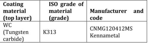
Table-2: Cutting tool name and code
Coating material (top layer)
ISO grade of material
(grade) Manufacturer and code
WC (Tungsten
carbide) K313
CNMG120412MS Kennametal
Elements Ni Cr Fe Si Mn Mo Co Nb+Ta Al P Ti
Inconel
© 2017, IRJET | Impact Factor value: 5.181 | ISO 9001:2008 Certified Journal | Page 567
[image:3.595.49.290.126.228.2]4. EXPERIMENTS PERFORMED
Fig 4: Work piece after machining
1. On nine work pieces of inconel 625 the experiment is carried out.
2. All the work pieces are turned on CNC machine. The dimensions of each work piece is [Total length of work piece (L)=80 mm, Initial Diameter (D) =30 mm, Turned length of work piece (l) =10 mm & final diameter (d) =24.5mm 3. For each work piece time is measured with the help of stop watch.
4. By using the initial & final diameters and machining time, material removal rate is calculated by using the formula. Where, D =Work piece diameter before turning in mm, d = Work piece diameter after turning in mm, L =Work piece length in mm.
5. Surface roughness of all work pieces is measured by using surface roughness tester.
6. The analysis is carried out by using Taguchi method with the help of Minitab-17 software
4. CUTTING TOOL MATERIALS
Material selection and geometry, is one of the most important factors that influence surface roughness and the mechanical properties. Tool materials, apart from having to satisfactorily endure the milling operation, affect surface roughness and tool wear. In the context of machining, a cutting tool is any tool that is used to remove material from the work piece by means of shear deformation.
Table-2: Chemical composition of Tungsten Carbide
Coating material (top layer)
ISO grade of material
(grade) Manufacturer and code
WC (Tungsten
carbide) K313
CNMG120412MS Kennametal
5. RESEARCH ON CNC TURNING OF Inconel 625
V.Paramasivam et al.[1]. They investigated the optimization of turning process parameters for EN24 steel based on Regression analysis. The L9 orthogonal is used for the experiment cutting speed, feed rate and depth of cut are
considered as input parameters and material removal rate and surface roughness are output parameters. From the experiment study it can be seen that cutting speed has the significant effect on MRR and surface roughness when compared to feed rate.
Narayana reddy et al. [2].The machining parameters of 20MnCr5 steel were analyzed in CNC horizontal lathe. The Taguchi method is used for optimization. The L9 orthogonal array, signal to ratio and Analysis of variance were employed to study the performance characteristics in turning operation. In this study they have used four input parameter like cutting speed, feed rate, depth of cut and hardness of the cutting tool for identifying the output parameters like surface roughness and MRR.
Shunmugesh et al. [3] .They have made attempt to search for a set of optimal process parameter value that leads to minimize the value of machining performance. This study aimed at optimizing machining performance and the input parameters for 11sMn30. The input parameters considered for the study were speed, feed and depth of cut. The Taguchi analysis is used for optimizing the machining parameter.
Aravind kumar. [4].He has optimized the turning parameters for mild steel 1018. He used three cutting parameters to find out the maximum metal removal rate from the manufactured component. The CNC turning machine was used for this study.
For the optimization purpose the Taguchi approach with L27 orthogonal array is used. He revealed, that the feed rate in influence the material removal rate.
Anand S. Shirade et al.[5].The experiment was conducted to determine the optimum cutting parameters setting for minimizing surface roughness when turning of EN8 steel material. The L9 orthogonal array design is used for design the experiments. The analysis of variance (ANOVA) employed to analysis the influence of performance parameters during turning.
Shreemoykumarnayaket al.[6].The Investigation was carried out the effect of machining parameters during dry turning of AISI 304 austenitic stainless steel. For this study HMT heavy duty lathe machine was used. They have adopted L27 orthogonal array with three machining parameters like cutting speed, feed rate and depth of cut and three importance characteristics of machinability such as material removal rate (MRR), cutting force and surface roughness (Ra) were measured. For the optimization of machining parameters, Grey relational analysis was used.
[image:3.595.36.289.615.688.2]© 2017, IRJET | Impact Factor value: 5.181 | ISO 9001:2008 Certified Journal | Page 568 study indicate that the feed rate is mostly influencing the
surface roughness of the machined surface. Neerajsaraswat et al.[8].They determined the optimal cutting parameters for EN9 steel in turning operation. The analysis of variance (ANOVA) and signal to noise ratio (S/N ratio) were used to study the performance characteristics in turning operation. The cutting speed, feed rate and depth of cut were selected as a input parameters to optimize the surface roughness.
6. RESEARCH GAP, PROBLEM AND CHALLENGE
Generally, Super alloys are machined on the CNC turning. Inconel 625 is on which optimization experiment can be performed to find out the set of optimum values of process parameters in order to reduce surface roughness (SR) and increase material removal rate (MRR). Inconel 625 material is the most difficult material to machine. Improper selection of machining parameters causes cutting tool to wear and break quickly as well as economic losses such as damaged work piece and rejected surface quality. Machining parameters and tool geometry are the important parameters which affect the machinability properties.
The regression is a statistical procedure that allows a researcher to estimate the linear or straight line relationship that relates two or more variables. This linear relationship summarizes the amount of change in one variable that is associated with change in another variable or variables. The model can also be tested for statistical significance, to test whether the observed linear regression model is discussed. In a second course in statistical methods, multivariate regression with relationship among several variables, is examined.
In the regression model, the independent variable is named the X variable, and the dependent variable the Y variable. The relationship between X and Y can be shown on the graph, with the independent variable X along the horizontal axis, and the dependent variable Y along the vertical axis. The aim of the regression model is to determine the straight line relationship that connects X and Y.
Y=a+bX1+cX2+……….Xn
This regression analysis is done by using resent software application called MINITAB.
Regression analysis is used when two or more variables are thought to be systematically connected by a linear relationship. In simple regression, we have only two let us designate them x and y and we suppose that they are related by an expression of the form
y = a + bx +……..
We’ll leave aside for a moment the nature of the variable and focus on the x - y relationship. y = a + bx is the equation of a straight line; a is the intercept (or
constant) and b is the x coefficient, which represents the slope of the straight line the equation describes. To be concrete, suppose we are talking about the relation between speed feed DOC and MRR Surface roughness.
6.1TAGUCHI DESIGN OF EXPERIMENTS
Taguchi method is a powerful tool in quality Optimization makes use of a special design of Orthogonal Array (OA) to examine. Number of experiments used to design the orthogonal array for 3 parameters and 3 levels of milling parameters [9].
Minimum experiments = [(L – 1) X p] + 1
6.1.1 DEGREES OF FREEDOM
Number of parameters = 3
Number of levels for each parameters = 3
Total degree of freedom (DOF) for 3 parameters = 3x (3-1) = 6 Minimum number of experiment =
Total degree of freedom for parameters + 1
Minimum number of experiments = 6+1 Minimum number of experiments = 7
For the above process parameters and their levels, the minimum numbers of experiments to be conducted are 7. So that is why nearbyL9 orthogonal array is taken =
[(3 – 1) X 3] + 1 = L9
6.2TAGUCHI ORTHOGONAL ARRAY
There are three signal-to-noise ratios of common interest for optimization of static problems
1) Smaller-The-Better n = -10 Log10 [mean of sum of squares of measured data]
This is usually the chosen S/N ratio for all undesirable characteristics for which the ideal value is zero. But when the ideal value is zero, then the difference between measured data and ideal value is expected to be as small as possible. The generic form of S/N ratio becomes:- n = -10 Log10 [mean of sum of squares of {measured - ideal}]
2) Larger-The-Better n = -10 Log10 [mean of sum squares of reciprocal of measured data
© 2017, IRJET | Impact Factor value: 5.181 | ISO 9001:2008 Certified Journal | Page 569
Table 6.2: Taguchi Orthogonal Array
Test Number
Input Machining Parameters
Speed
(rpm) Feed (mm/rev)
Depth of cut (mm)
1 742 0.06 0.4
2 742 0.10 0.6
3 742 0.14 0.8
4 848 0.06 0.6
5 848 0.10 0.8
6 848 0.14 0.4
7 955 0.06 0.8
8 955 0.10 0.4
9 955 0.14 0.6
[image:5.595.53.272.106.305.2]6.3 S/N Ratio For Material Removal Rate
Table 6.3: S/N Ratio For Material Removal Rate
Sl No. SPEEDFEED DOC MRR SNRA (rpm) (mm/rev) (mm) (mmsec) 3/
1 742 0.06 0.4 27.26 28.7105
2 742 0.10 0.6 68.34 36.6935
3 742 0.14 0.8 125.98 42.0060
4 848 0.06 0.6 46.18 33.2891
5 848 0.10 0.8 102.74 40.2348
6 848 0.14 0.4 73.15 37.2843
7 955 0.06 0.8 69.70 36.8647
8 955 0.10 0.4 58.89 35.4008
9 955 0.14 0.6 122.84 41.7868
6.4 S/N Ratio For SURFACE ROUGHNESS
Table 6.4: S/N Ratio For Surface Roughness
Sl No. SPEED FEED DOC RA SNRA
(rpm) (mm/rev) (mm) (µ)
1 742 0.06 0.4 2.262 -7.0899 2 742 0.10 0.6 3.152 -9.9717
3 742 0.14 0.8 3.756 -11.4945
4 848 0.06 0.6 2.275 -7.1396 5 848 0.10 0.8 2.746 -8.7740 6 848 0.14 0.4 1.852 -5.3528 7 955 0.06 0.8 3.105 -9.8412 8 955 0.10 0.4 2.124 -6.5431 9 955 0.14 0.6 2.652 -8.4715
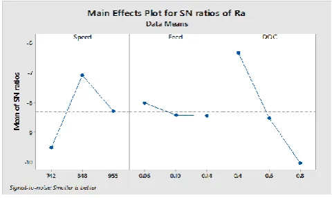
6.5.1 RESPONSE TABLES FOR SR
[image:5.595.309.561.302.377.2]
Table 6.5.1: Response Table for S/N Ratios Smaller is better
Level Speed Feed Doc
1 -9.519 -8.024 -6.329
2 -7.089 -8.430 -8.528
3 -8.285 -8.440 -10.037
Delta 2.430 0.416 3.708
Rank 2 3 1
6.5.2 RESPONSE TABLES FOR MRR
[image:5.595.54.269.361.519.2]
Table 6.5.2: Response Table for S/N Ratios Larger is better
Level Speed Feed Doc
1 35.80 32.95 33.80
2 36.94 37.44 37.26
3 38.02 40.36 39.70
Delta 9.95 59.61 46.37
Rank 3 1 2
6.6 MAIN EFFECT PLOTS ANALYSIS FOR MRR
Figure 6.6: Main effect plots S/N ratios for MRR
6.7 MAIN EFFECT PLOTS ANALYSIS FOR SR
[image:5.595.304.558.410.550.2] [image:5.595.313.555.608.751.2]© 2017, IRJET | Impact Factor value: 5.181 | ISO 9001:2008 Certified Journal | Page 570
[image:6.595.56.264.142.328.2]6.8 ANOVA RESULTS FOR S/N RATIOS OF MRR
Table 6.8.1: ANOVAfor S/N ratios of MRR
Source DF Adj SS Adj MS F-Valu e
P-Valu e Regressi
on 3 8704.7 2901.57 41.13 0.001
Speed 1 149.0 148.95 2.11 0.206
Feed 1 5330.0 5330.0 75.56 0.000
DOC 1 3225.7 3225.73 45.73 0.001
Error 5 352.7 70
Total 8 9057.4
6.9 ANOVA RESULTS FOR S/N RATIOS OF SR
Table 6.9.1: ANOVAfor S/N ratios of SR
Source DF Adj SS Adj MS F-Value P-Value Regression 3 2.23005 0.74335 5.59 0.047
Speed 1 0.27470 0.27470 2.06 0.210
Feed 1 0.06365 0.06365 0.48 0.520
DOC 1 1.89169 1.89169 14.21 0.013
Error 5 0.66548 0.13310
Total 8 2.89553
6.10 Regression Equation for Surface Roughness (Ra)& MRR
Ra = 2.42 - 0.00201 Speed + 2.58 Feed + 2.808 DOC MRR = -106.5 + 0.0468 Speed + 745.1 Feed + 115.9 DOC
The equation obtained from the Regression analysis method is import to the Genetic Algorithm Tool in MATLAB application, the following two equations are written in the supportable equation form
MRR=-106.5+0.0468*x(1)+745.1*x(2)+115.9*x(3) Ra =2.42-0.00201*x(1)+2.58*x(2)+2.808*x(3)
The fitness function is created by using above equations separately, it means Material Removal Rate equation is written in Editor Column in MATLAB. The following is the fitness function format for MRR and Ra
1) function y=MRR(x)
y=-106+0.0468*x(1)+745.1*x(2)+115.9*x(3); end
2) function y=Ra(x)
y =2.42-0.00201*x(1)+2.58*x(2)+2.808*x(3); By clicking the start button, processes starts and it shows the iterations in the iteration block and final results will shows below that iteration block. Finally it shows the final number of iteration at which optimal level is obtained. And it also shows the combination of the parameters. The following GA graphs shows the MRR and Ra values.
[image:6.595.323.534.229.421.2]6.10.1 GENETIC ALGORITHM PLOTS FOR SR
Figure 6.10.1: Best fitness and Expectation for MRR at 51st iteration
6.10.2 GENETIC ALGORITHM PLOTS FOR MRR
Figure 6.10.2: Best fitness and Expectation for Raat 51st
[image:6.595.316.540.501.707.2]© 2017, IRJET | Impact Factor value: 5.181 | ISO 9001:2008 Certified Journal | Page 571
7. CONCLUSIONS
Surface roughness (SR) and material removal rate (MRR) are very important factor for determining product quality. Machining parameters like cutting speed, feed rate, and depth of cut are crucial to roughness free surface. CNC Turning gives a good surface finish of Inconel625. For Experimental design, Taguchi method will be used for optimization process. By using ANOVA (Analysis of variance) Method, find out the significant factor and percentage contribution of each input parameter for obtaining optimal conditions.
The experimental results showed that the Genetic Algorithm parameter design is an effective way of determining the optimal cutting parameters for the MRR and Surface roughnes evaluation compare to Taguchi. The optimal parameters are cutting speed 742 rpm, feed 0.06 mm/rev and depth of cut 0.4 mm gives the high MRR within the range of experiments. And for the Surface roughness the optimal parameters are cutting speed 949rpm, feed 0.06, depth of cut 0.4 .This review article will covers the effect of process parameters that are influence on surface roughness (SR) and material removal rate (MRR) by plotting the various graphs. Finally from the experimentation, it is found out that the set of optimum values of process parameters in order to reduce surface roughness (SR) and increase material removal rate (MRR) for the purpose of machining Inconel 625.
REFERENCES
[1] V.Paramasivam, B.Moinudeen, P.Premkumar, Optimization of turning process parameters for EN-24 steel using Taguchi method and Regression Analaysis, Global Journal Of Engineering Science and Researches, pp 31-38, Oct 2014.
[2] NarayanaReddy. A R1 Gantisatyaprakash, Optimization of Machining Parameters of 20MnCr5 Steel in Turning Operation using Taguchi technique, International Journal Of Modern Engineering Research, Vol.4, pp.50-60, Sep 2014.
[3] Shumugesh k, Panneerselvam K, Pramod M and AmalGeorge, Optimization of CNC Turning Parameters with carbide tool for surface roughness analysis using Taguchi Analysis, Research Journal Of Engineering Science, Vol.3, pp.01-07, June 2014.
[4] Arvind Kumar, Optimization of Material Removal Rate in CNC Turning of Mild Steel 1018 using Taguchi method, IJITKM Special Issue, pp. 231-237, May 2014.
[5] AnandS.Shivade, Shivraj Bhagat, SurajJagdale, AmitNikam, Pramodlondhe, Optimization of Machining Parameters for Turning using Taguchi Approach, International Journal Of Recent Technology and Engineering, Vol.3, Issue.1, pp.145-149, March 2014.
[6] Sheermoykumar Nayak, Jatinkumarpatro, ShaileshDewangan, Soumya Gangopadhyay, Multi objective optimization of machining parameters during dry turning of AISI 304 Austenitic stainless steel using Grey Relational Analysis,www.sciencedirect.com, pp.701-708, 2014.
[7] Sachin C Borse, Optimization of turning parameters in dry turning of SAE52100 steel, International Journal Of Mechanical Engineering and Technology, Vol.5, Issue.12, pp.01-08, Dec 2014.
[8] NeerajSaraswat, Ashok Yadav , Anil Kumar and Bhanu Prakesh Srivastava , Optimization of Cutting Parameters in Turning Operation of Mild Steel, International Review Of Applied Engineering Research, Vol.4, pp.251-256, 2014.
[9] Anjaneyulu, B., et al. "ANALYSIS OF PROCESS PARAMETERS IN MILLING OF GLASS FIBRE REINFORCED PLASTIC COMPOSITES.". Volume 8, Issue 2, February 2017, pp. 149–159 Article ID: IJMET_08_02_018, ISSN Print: 0976-6340 and ISSN Online: 0976-6359