© 2018, IRJET | Impact Factor value: 6.171 | ISO 9001:2008 Certified Journal | Page 1985
Numerical Study of Heat Transfer Characteristics on a Dimpled Surface
plate using Pulsating Jet Impingement Array
Anish Chackappan
1, Sabu Kurian
21Student, Dept. of Mechanical Engineering, M A College of Engineering, Kerala, India 2Associate Professor, Dept. of Mechanical Engineering, M A College of Engineering, Kerala, India
---***---Abstract –
It is of imperative concern that the energy we are producing through diverse process are not living up to their maximum potential in our lives. Most of the energy is being circulated into atmosphere because of which maximum efficiency is never reached. Heat transfer is much more involved in our daily lives than we realize. A great part of energy that we utilize is in the form of thermal energy. The knowledge of Heat transfer therefore is crucial for designing power systems that involve heat. Unrelenting power surges in devices, such as processors are requiring high capacity cooling techniques to remove excess heat. One such method is the jet impingement of a liquid or gas onto a surface on a continuous basis. It’s being tested for quite some time and results have been staggering. In this paper we have actually included as different as four factors together who have shown in past to increase the heat transfer rate as possible. It was found that increase in surface area as well as increasing the air domain area for medium frequency rates resulted in high heat transfer rate in lesser time possible. As high as 36% increase was noted in the preliminary results when the basic condition was compared with the increase in surface are using dimples and frequency factors. Optimization was done for a cluster of designated cases and through which the best condition was found.Key Words: Concave Dimpled Surface, Heat Transfer Coefficient, Jet Impingement, Nusselt Number, Reynolds Number, Turbulence.
1. INTRODUCTION
Heat Transfer fills that gap which thermodynamics don’t. Thermodynamics deals with the amount of energy required to change a system from one equilibrium state to another. The science of heat transfer deals with the rate of heat flow within a medium or between two bodies. We actually seek to understand the mechanism of jet impingements in order to understand which factor contribute in maximizing the available rate of heat transfer. Jet Impingement is one the novel ways to increase the heat transfer rate since it is effective and flexible in transferring energy from one system to another in industrial or commercial applications.Jets can be classified as submerged and unsubmerged. Several configurations have been tested such as: jets issuing from orifices or round and slot nozzles different types of jet arrays; flat and curved impingement surfaces, normal and inclined impingement, etc. Heat transfer rate can also be improved by enhancing the thermal characteristics of the working fluid.
Impingement jets are essentially air-powered or else use some type of liquid, typically water. There are three common jet configurations: the free-surface jet, which uses dense liquid in a medium that is less dense, such as air; the submerged jet, which allows the fluid to impinge in the same medium fluid; and the confined submerged jet. In this paper we are using confined submerged jet which is using the same type of fluid to impinge in the same medium fluid.
To determine which factor approves the most transfer of heat rate is complicated though in a confined set of range in the factors we can provide a rough sketch of which factor is dominating comparing to other factors through optimization methods and techniques. Among the most critical are the Reynolds number, frequency, jet diameter, and wall-to-nozzle spacing. Hence we included a new factor, dimple’s diameter to height ratio so as to increase the surface area pocket.
© 2018, IRJET | Impact Factor value: 6.171 | ISO 9001:2008 Certified Journal | Page 1986 from 6000 to 60000, R from 0 to 10, and H from 1 to 12.
Results showed that the maximum stagnation Nusselt value occurred at H = 4.7. Nusselt number was a strong function of H and R. Physical Experiment was conducted on Measurements of impinging jet flow and heat transfer on a semi-circular concave surface by Mansoo et al., [6] which concluded that for the case of H/D = 0.4, the effect of fluid acceleration has been erased. The evolution of wall jets has been successfully measured by a Laser Doppler Velocimeter. The occurrence of secondary peaks and their locations have been explained from the variation of measured velocity fluctuations of the wall jets evolving along the stream wise direction. Comparative study of turbulent mixing in jet in cross-flow configurations using LES was done by Wegner and Wegner [7] which concluded that angle between the jet and the cross-flow. From an engineering point of view, it seems favourable to inject the jet at an angle inclined against the oncoming main flow. The increased mixing could help build shorter, lighter and cheaper devices.
Experimental paper titled Effect of Pulsating Circular Hot Air Jet Frequencies on Local and Average Nusselt Number by Rozli et al. [8] proved that The stagnation point heat transfer does not show any enhancement for the three Reynolds numbers investigated namely 16000, 23000, 32000. The average Nusselt number for the pulse jet is enhanced for all the frequencies investigated. The degree of enhancement is in the range 30-80%. Heat transfer in the pulse flow mode is complex and dependent on the flow structure of the jet.
Breakthrough paper by Hofmann et al. [9] titled Influence of a pulsation on heat transfer and flow structure in submerged impinging jets concluded experimentally that Convective heat transfer can be influenced by periodic fluctuations in the mean flow. The main mechanism, which was identified is, that the pulsation enhances mixing between the jet and the environment and yields to a reduction in the jet velocity. Experimental Investigation of Heat transfer of impinging jet-array onto concave- and convex-dimpled surfaces with effusion by Chang and Liou [10] stated that Without effusion, the NuC with concave dimples are less than their counterparts with convex dimples. For each dimpled surface at all E/H tested, the differences in Nu between non-effusion and effusion results consistently decrease as Re increases. The Nu over the concave-dimpled surface at each E/H examined recover at the faster rates than their convex counterparts. Numerical study on Turbulent impinging jet heat transfer enhancement due to intermittent pulsation was conducted by Peng et al. [11] stated that significant enhancement of heat transfers at the target surface by the intermittent pulsation in a turbulent impinging jet over a wide range of parameters for both of cooling and heating cases.
Numerical study was conducted titled A study on the heat and mass transfer properties of multiple pulsating impinging jets by Peng et al., [12] stating that The RNG k-ε turbulence model is numerically robust and fast, and has been proven to be effective in modelling this type of complex flows in
impinging and opposed jets. The numerical results show that symmetrical pulsations with no phase angle difference indicate marginal influence on the heat transfer coefficient, while the pulsations with phase angle difference can significantly improve convective heat transfer rate around secondary stagnation point as the oscillatory flow can eliminate the formation of the static stagnation point.
Experimental Paper on Flow and Heat Transfer Characteristics of Single Jet Impinging on Dimpled Surface by Yonghui et al., [13] stated that The local Nusselt number in the dimple cavity decreases after arranging the dimple, and it is lower with deeper dimple. The local Nusselt number in the latter part of the dimple periphery region experiences a decrease-increase-decrease process, and it recover to the same level departing from the dimple periphery region.
Experimental study on Heat Transfer Enhancement by Jet Impingement on Dimpled Surface with Different Cavities by Lutade et al. [14] showed that use of dimples increased the heat transfer rate with spherical cavity bringing the highest augmented heat transfer. At H/D=2, flow got trapped in between the nozzle plate and test plate while at H/D=4 there is highest augmentation in heat transfer. Whereas at H/D=8, jet loses its confinement and mixes with adjoining jets leads to the poor heat transfer rate.
Many investigations have been done on heat transfer through jet impingement case, however we find a research gap in between all the papers where there is not much investigation has never been done. The present work intents to numerically investigate and optimize the thermal characteristics in jet impingement process without cross flow with a limited number of factors with certain levels. This study aims to assess the heat transfer characteristics, Heat transfer coefficient, Temperature and Nusselt Number and with respect of results, it will optimize of all the conditions to find the best suited case of all ranges in the following research gap.
2. NUMERICAL MODEL
2.1 Physical Geometry
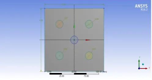
[image:2.595.311.560.615.746.2]The basic geometric model of jet impingement process along with nozzle inlet is shown in figure 1a.
© 2018, IRJET | Impact Factor value: 6.171 | ISO 9001:2008 Certified Journal | Page 1987 In total five nozzles are placed in staggered formation [15].
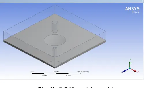
[image:3.595.37.287.167.319.2]The staggered formation is considered more adjacent to achieving higher heat transfer results. All nozzles take same amount of attacking fluid at common velocity and operate together at the same time. In figure 1b we can see the 3-D view of the quarter of the entire figure since all the four sides are in symmetry with each other.
Fig -1b: 3-D View of the model
From the inlet the cooling fluid attacks on the heating plate shown in grey color and the rest area is taken up as air domain where the total dynamics of flow field and temperature transference is witnessed.
2.2 Governing Equations
Using commercial software ANSYS Fluent 16.2 [12], governing equations for flow conditions and heat transfer were numerically solved based on following assumptions: transient-state, incompressible and Newtonian turbulent fluid flows with constant heat flu to the heating plate. Numerical simulation of the flow and thermal fields in a semi-confined turbulent impinging jet requires the solution of Continuity Eq., Navier–Stokes Eq., Energy Eq. along with appropriate turbulence model equations. The viscous heating and compression work are both trivial and thus are neglected in the energy equation [7].
The resulting governing equations are:
Continuity equation:
Momentum equation:
Energy equation:
where u, ρ, ν and Pr are the average velocity, density, kinematic viscosity and Prandtl number, respectively.
Re-Normalized Group k-ε turbulence model is adopted in the current study because it is numerically robust and can provide superior performance for flows involving rotation, boundary layers effect under strong adverse gradient of pressure and recirculation [1]. The transport equations in the realizable k-ε model are given below:
Turbulent kinetic energy k equation:
(4)
Turbulent energy dissipation ε equation:
(5)
where:
(6)
(7)
(8)
It is interesting to note that the values of most of the constants are derived explicitly in the RNG procedure. They are given below with the commonly used values in the standard k-epsilon equation in brackets for comparison:
The enhanced wall function is used for the numerical computation near the wall to avoid problems of successive refinements in standard wall function meshes.
3. PROBLEM’S OBJECTIVE
3.1 Brief Overall Objective
© 2018, IRJET | Impact Factor value: 6.171 | ISO 9001:2008 Certified Journal | Page 1988 as possible for the given inputs. Here the inputs are
positioned in ranges which are calculated as per research gap and in that gap the maximum heat transfer rate is found and optimized for the given cases.
Table -1: Input Parameters with respected ranges
Parameter Value Range
Height between Nozzle to the Target
plate to diameter (H/D) 1,2,34
Frequency (pulsations) (f) 40,50,60,70
Reynolds Number (Re) 16000,20000,24000,28000
Dimple’s Diameter to Height ratio (l/b) 1,4,9,16
Following given are the inputs (factors) which are also divided into 4 levels which will be varying for the respected ranges. For every case there will be a results providing the Nusselt Number (Nu) for them. Fluid flow will always be pulsated (f) for the given velocity (v) corresponding to the Reynolds Number (Re) provided. The height of the domain is specified as (L) which will be changing as per table. Diameter (D) of the nozzle is kept constant at 5mm.
The height (l) to diameter (b) ratio of the dimple varies so that the surface area of the plate should increase and give way to amplified heat transfer rate. The heating plate is placed at the constant heat flux condition at 8333.33 W/m2.
Plate is 120x120 mm with 2mm depth of same material.
Nozzle to Nozzle distance is kept at constant at 60mm to each other in staggered form. Every factor is divided into 4 different levels. All the four factors apply together for a certain time interval in the computational process. Since the geometry is perfectly symmetric in all directions. Hence only a quarter of the actual 3-D figure is taken into computational account.
Hence the plate reduces to (60x60) mm with only one complete nozzle and a quarter of another nozzle appearing at the end of the figure as shown in the figure 1b. Since the number of elements will be divided by 4 times hence the computational time will be lessening by 4 times therefore.
3.2 Boundary Equations
Table -2: Properties of Air at 300K
Parameter Value
Specific Heat (Cp) 1.0049
Specific Heat (Cv) 0.7178
Dynamic Viscosity (µ) 1.846 x 10⁻⁵
Thermal Conductivity (k) 0.02624
Prandtl Number (Pr) 0.707
Density (ρ) 1.177
Following are the properties which were included in the computational software ANSYS 16.2[16] before starting the computation for dry air at 300K (Temperature). Along with that some other basic parameters were also included in the software which didn’t change themselves throughout all the computational cases.
Table -3: Boundary Conditions
Parameter Value Range
Heat flux to heating plate (W) 120
Turbulence Model K-epsilon
Turbulence Viscosity Ratio 10
Temperature of Incoming Air (K) 300
3.3 Design of Experiments and Optimization
If we consider all the levels with all the factors for every case we have, we can figure our way for 256 cases which is a time disaster judging by our level of work. Since we can’t perform all the individual cases, there are certain techniques through which amount of these cases can be reduced. For e.g. Latin Hypercube technique and Taguchi Orthogonality Array method. Hence Taguchi method is used because of its capability and the number of cases were reduced from 256 to 16 containing all the aggregate effect of all the 256 combinations.
Table -4: Total Amount of Cases
No. Re l/b L/D F
1 16000 4 1 40
2 16000 8 2 50
3 16000 12 3 60
4 16000 16 4 70
5 20000 4 2 60
6 20000 8 1 7
7 20000 12 4 40
8 20000 16 3 50
9 24000 4 3 70
10 24000 8 4 60
11 24000 12 1 50
12 24000 16 2 40
13 28000 4 4 50
14 28000 8 3 40
15 28000 12 2 70
16 28000 16 1 60
© 2018, IRJET | Impact Factor value: 6.171 | ISO 9001:2008 Certified Journal | Page 1989 4. CFD SIMULATION
All governing equations were solved by the control volume approach using commercial software ANSYS Fluent 16.2. The double precision option was adopted for all computations, since it will include all the 6 digit significant values to the answer. The velocity components are evaluated at the control volume faces, while the rest of the variables governing the flow field are stored at the central node of the control volume. The flow and thermal fields was computed with the finite volume computational fluid dynamics (CFD) code FLUENT.
In pulsed turbulent impinging jets, turbulence components are highly anisotropic due to strong compression of turbulence, chaotic mixing and nonlinear dynamic response of boundary layers. The RNG k-ε turbulence model is numerically robust and fast, and has been proven to be effective in modelling this type of complex flows in impinging and opposed jets [15].
Thus, in the current study, Re-Normalized k-ε model was used to model the turbulent behaviour of the flow in the pulsating impinging jet. The uniform velocity, turbulent kinetic energy and energy dissipation rate profiles were assumed at the nozzle exit, and pressure outlet boundary condition was taken at outlet planes. The initial conditions (t=0) throughout the computational domain can be described as: u=v=0, p=p∞, T=T∞. A second upwind discretization scheme was used considering the stability of solution convergence.
The pressure-velocity coupling was handled with the SIMPLEC scheme. This algorithm can be used to properly simulate the real time environment which is specified in the boundary conditions provided in the Table 3. Fluent solves the linear systems resulting from discretization schemes using a point implicit (Gauss–Seidel) linear equation solver, in conjunction with an algebraic multi-grid method. For all simulations performed in the present study, converged solutions were considered when the normalized residuals resulting from an iterative process for all governing equations were lower than 10-6.
4.1 Grid Independence Study
[image:5.595.314.565.79.234.2]Seven different meshes were considered for establishing the grid independence of the model under the present study. In each case, the heating plate temperature and surface area averaged Nusselt Number was recorded and tabulated as shown in table 5 to achieve the grid independency. From the tabulated results, it was concluded that grid independency was achieved for Mesh - 5 and this mesh was used for further numerical computations.
Fig -2: Grid Independency Graph
Table -5: Grid independence study
Mesh Grid Temperature (K)
Mesh-1 (241128) 371.672
Mesh-2 (351863) 346.918
Mesh-3 (492103) 334.346
Mesh-4 (793648) 328.027
Mesh-5 (1175977) 324.127
Mesh-6 (1299813) 326.552
Mesh-7 (1394431) 324.880
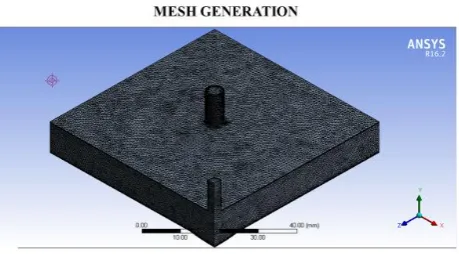
Since there are in total 16 cases, grid study was done for a case which is medium to all the other cases and the resultant grid mesh which got accepted is used to mesh all the other meshes in all cases. Figure 3 showing the accepted mesh.
Fig -3: Meshed view of the generated model
4.2 Model Validation
The computational domains are meshed with face meshing and it contain a mix of hexahedral and wedge elements. Figure 2 shows the grid independency graph for the seven meshes.
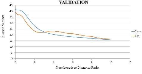
[image:5.595.321.551.496.623.2]© 2018, IRJET | Impact Factor value: 6.171 | ISO 9001:2008 Certified Journal | Page 1990 5500 for a frequency of 41 HZ at L/D = 5. Numerical results
[image:6.595.316.553.76.214.2]were in good agreement with the experiment results. Mladin carried out experiment on local convective heat transfer to submerged pulsating jets. Figure 4 shows the graph between Nusselt Number and plate distance for both cases.
Fig -4: Validation Curve
From the graph as we can see that there is an overall average deviation of 8.6% with maximum deviation occurring just after 0 on radial distance for 15.1%.
Overall the following turbulence model (k-epsilon) is proving to be a good model in predicting flows around heating plate having dimpled indentations for the purpose of formation of vortices.
5. RESULTS AND DISCUSSIONS
Heat transfer characteristics and flow dynamics are closely discussed in the simulation and the changes which are produced when all the factors played together are noted in terms of contours and plot between factors and response variable. We noticed that for low frequency ranges and high air domains and for vice-versa in reverse, there is an augmented heat transfer rate in the computational domain.
5.1 Variation of Nusselt Number
Following are the Nusselt number contours for all the cases computed in transient mode for 0.3 secs. Out of the given 16 cases which are decide by the Taguchi Orthogonality Method, only main cases are presented here on the sectional basis of Reynolds Number. From Case (1-4), Case 4 got the best imprints while in the next consecutive sections, Case 8, Case 9, Case 15 found the best results respectively. These were the cases which provided most transfer rate in the given provided time as soon as possible.
[image:6.595.51.290.151.275.2]Fig -5: Optimum Result from Cases (1-4)
[image:6.595.317.549.242.378.2]Fig -6: Optimum Result from Cases (5-8)
Fig -7: Optimum Result from Cases (9-12)
From figure 5-8 all the best cases are only represented here. As you can see from above shown results in figure 5 and figure 6, in the given due time the jet impingement process started to work brilliantly providing a maximum Nusselt number of 65.161 for case 8. Low air-domain ratio with low frequency can be a deciding factor for the flow to gather momentum and provide high heat transfer.
[image:6.595.318.548.406.543.2]© 2018, IRJET | Impact Factor value: 6.171 | ISO 9001:2008 Certified Journal | Page 1991
Fig -8: Optimum Result from Cases (13-16)
Because time restraint was a motive so as to find the best set of case which could provide maximum heat transfer rate in less time to the application. Contours are to be view from left to right in order.
[image:7.595.304.563.70.308.2]As we can see from figure 7 and figure 8 we can see a more refined distribution of the flow field in the given dynamics. Out of all the cases the maximum Nusselt number occurred in the case 15 where all the condition is in perfect synchronization with each other, though it is not producing the maximum Nusselt number in time but the spread of the flow as well as the velocity is working together good. In Table 6, all the maximum and average values of the quantity Nusselt number are given which are found through the computational process.
From the given table 6 we can easily take out the best and the worst case. As you can see the Nusselt number contours are in perfect agreement with the given results with each other. For more Reynolds number like 28000, the more heat transfer rate is found since throughout all the cases.
When the dimple ratio is near to 4 and the air domain corresponds to 3, more heat transfer is generated for high as well as low frequencies. Since the flow all are in pulsating motion, there is no continuous effort done by the fluid (incoming) and the maximum potential is able to come out of the process. Since in every case the air gap (domain) is changing, hence the flow dynamics is also changing along with it.
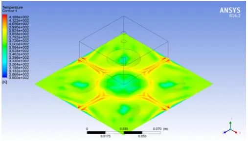
4.2 Variation of Temperature (Diagonally)
Following are the variations which are achieved in temperature contours when simulated through ANSYS 16.2 for the same conditions depicted in Table 4. As you can see in the former cases from 1-4 there isn’t much of a development because of the low momentum gathered by the flow field in the given due time.
Table -6: Case Results
Case
No. Nusselt No. –Plate Temperature Average Nusselt No. – Plate (max)
1 13.0339 424.889 43.7395
2 17.6391 392.89 51.5755
3 20.0805 381.92 65.838
4 20.3969 379.317 61.55
5 20.9915 378.48 56.534
6 18.2326 389.51 43.0743
7 20.6552 383.418 58.511
8 21.9452 378.618 65.161
9 26.3368 364.465 70.467
10 24.1598 370.356 61.513
11 16.5043 398.668 43.1687
12 19.435 384.808 55.3725
13 26.213 366.245 64.6305
14 25.4029 367.565 63.861
15 27.0538 361.643 69.837
16 19.932 381.93 46.1961
Out of all the cases, Case 15 showed the best results in lesser time provided. Due to high pulsations created in the air domain with the help of a user defined function in the ANSYS module, we were able to mimic the pulsation condition in the project. The area just below the nozzle is incidentally equal to the extra surface are which is produced by the dimple’s indentation. The indentation made it possible to lag the stagnation point of the jet nozzles as well as to increase the heat transfer rate.
The air domain in these cases is 1 or 2 which is too less space for the flow to gather any force or momentum so that it can gain more heat from the heating plate. Cases 4,7,5,8 are displaying key oddity in increasing heat transfer rate.
[image:7.595.307.565.73.307.2] [image:7.595.307.561.495.640.2]© 2018, IRJET | Impact Factor value: 6.171 | ISO 9001:2008 Certified Journal | Page 1992
[image:8.595.36.288.253.397.2]Fig -10: Optimum Results from Cases (5-8)
Fig -11: Optimum Results from Cases (9-12)
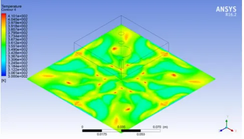
In the following vicinity the temperature is lower where the nozzle is acting force while in the areas which are away from the nozzles are building up the temperature gain. Partially it is because the flow is not totally gathering momentum in the space provided as shown in the cases 1,11,2,6.
Fig -12: Optimum Results from Cases (13-16)
5. CONCLUSION
Following paper was numerically conducted simulation on a confined submerged jet impingement process with same medium of fluid. The simulation was conducted in ANSYS 16.2 (Fluent). Re-Normalized Group k-epsilon was elected to conduct the situation with SIMPLEC algorithm with second order discretization so that more accuracy can be evaluated
in the residual results as well as in response factors. Cases 1,11,2,6 exhibited the pitiable results of all sections. Common aspect of all those cases were that the air domain gap was equal in length to the diameter. The fluid had no place or enough time to create vortices or to gather momentum gain. Since all the cases were done with second order discretization, accuracy is expected out of all the results. Cases 7.5,8,10 showed encouraging results since they were applied with a common Reynolds number which is a medium value and the frequency factor is low with more than enough space for the air domain.
Cases 14,13,9,15 showed the maximum heat transfer rate of all the cases. Main reason which can be put is Reynolds number (Re) and then the air domain ratio (L/D), Since both of them are the chief factors which funded in creating more heat transfer rate. From the General Linear Model, we predicted which factor will behave in what pattern and to what extent one factor can influence the other factor. With the annexation of more than 3 variables along with more than 3 levels, a perfect set of variables emerged with the highest heat transfer rate. Heat transfer rate will increase with the presence of the dimples on the surface.
REFERENCES
[1] Freidman SJ, Mueller AC (1951), “Heat Transfer to flat
surfaces”, Proc. Hen. Disc on Heat Transfer, Institution of Mech Engineers, London, Vol. 11, pp. 138-142.
[2] Kezios SP (1956), “Heat Transfer in the flow of a
cylindrical air jet normal to an infinite plane”, Ph. D Thesis, Illinois institute of Technology, Heat Transf., Vol. 125, pp. 151-157.
[3] L.F.A Azevedo, B.W. Webb, M. Queiroz (1994), “Pulsed
Air Jet Impingement Heat transfer”, Experimental Thermal and Fluid Science, Vol. 8, pp. 206-213.
[4] E. C. Mladin, D. A. Zumbrunnen (1996), “Local
Convective heat transfer to submerged pulsating jets”, International Journal of Heat and Mass Transfer, Vol. 40, pp. 3305-3321.
[5] Lianmin Huang, Mohamed S. EL-Genk (1994), “Heat
transfer of an impinging jet on a flat surface”, International Journal of Heat and Mass Transfer, Vol. 37 (13), pp. 1915-1923.
[6] Mansoo Choi, Han Seoung Yoo, Geunyoung yang, Joon
SIk Lee (2000), “Measurements of impinging jet flow and heat transfer on a semi-circular concave surface”, International Journal of Heat and Mass Transfer, Vol. 43, pp. 1811-1822.
[7] B. Wegner, Y. Huai, A. Sadiki (2004), “Comparative study
[image:8.595.40.284.501.640.2]© 2018, IRJET | Impact Factor value: 6.171 | ISO 9001:2008 Certified Journal | Page 1993
[8] Rozli Zulkifli, Kamaruzzaman Sopian, Shahrir Abdullah,
Mohd Sobri Takriff (2008), “Effect of pulsating Circular Hot air jet frequencies on local and average Nusselt Number”, American Journal of Engineering and Applied Sciences, Vol. 01, pp. 57-61.
[9] H. M. Hofmann, D. L. Movileanu, Matthias Kind, Holger
Martin (2007), “Influence of a pulsation on heat transfer and flow structure in submerged impinging jets”, International Journal of Heat and Mass Transfer, Vol. 50, pp. 3638-3648..
[10] Shyy Woei Chang, Hsin-Feng Liou (2009), “Heat transfer
of impinging jet array onto concave and convex dimpled surfaces with effusion”, International Journal of Heat and Mass Transfer, Vol. 52, pp. 4484-4499.
[11] Peng Xu, Boming Yu, Shuxia Qiu, Hee Joo Poh, Arun S
Mujumdar (2010), “Turbulent impinging jet heat transfer enhancement due to intermittent pulsation”, International Journal of Thermal Sciences, Vol. 49, pp. 1247-1252.
[12] Peng Xu, Shuxia Qiu, MingZhou Yu, Xianwao Qiao, Arun
Mujumdar (2012), “A study on the heat and mass transfer properties of multiple pulsating impinging jets”, International Communications in Heat and Mass Transfer, Vol. 39, pp. 378-382
[13] Yonghui Xie, Ping LI, Jibing Lan, Di Zhangr (2013), “Flow
and Heat transfer characteristics os simple jet impinging on Dimpled surface”, International Journal of Heat transfer, Vol. 135, pp. 052201-052216.
[14] P. V. Lutade, P. M. Khanwalkar, S. S. Kore, V. N. Kapatkar
(2015), “Heat transfer enhancement by jet impingement on Dimpled surfaces with different cavities”, International Journal on Theoretical and Applied Research in Mechanical Engineering, Vol. 4, pp. 2319-2323
[15] Prasant Anand Kumar Lam, K Arul Prakash (2017), “A
numerical investigation and design optimization of impingement cooling system with an array of air jets”, International Journal of Heat and Mass Transfer, Vol. 108, pp. 880-90.
[16] ANSYS FLUENT 16.2 User Guide, November 2016,