© 2017, IRJET | Impact Factor value: 6.171 | ISO 9001:2008 Certified Journal
| Page 1218
A NEW CONTROL METHOD FOR THE MULTI-AREA LFC SYSTEM BASED ON
PORT-HAMILTONIAN AND CASCADE SYSTEM
N. Narasimhulu
1, M.Ganesh Babu
2, K.Swathi
3, Dr. R. Ramachandra
41,3
Associate Professor and Head, Department of EEE, SKD College of Engineering, Gooty, AP, India
2,4PG Student, SKD College of Engineering, Gooty, AP, India
---***---
Abstract:
In this paper, a method based on thePort-Hamiltonian (PH) system and cascade system that is proposed to design some PID control laws for the multi-area LFC system successfully works out the aforementioned problem. Compared with the existed PID methods for the multi-area LFC system, the proposed method has two advantages, which are the decoupling of total tie-line power flow and the robust disturbance rejection. Finally the proposed method is simulated with and without reheated turbine in the environment of Matlab/Simulink to validate the advantages and robustness of proposed method.
Keywords:
Interconnected Power System, Multi AreaConcept, PID controller
I. INTRODUCTION
Traditionally, frequency regulation in power system is achieved by balancing generation and demand through load following, i.e., spinning and non-spinning reserves. The future power grid, on the other hand, is foreseen to have high penetration of renewable energy (RE) power generation, which can be highly variable. In such cases, energy storage and responsive loads show great promise for balancing generation and demand, as they will help to avoid the use of the traditional generation following schemes;
This can be costly and/or environmentally unfriendly. The main goals of Load Frequency control (LFC) are, to maintain the real frequency and the desired power output (megawatt) in the interconnected power system and to control the change in tie line power between control areas. So, a LFC scheme basically incorporates an appropriate control system for an interconnected power system, which is heaving the capability to bring the frequencies of each area and the tie line powers back to original set point values or very nearer to set point values effectively after the load change. This is achieved by the use of conventional controllers. But the conventional controllers are heaving some demerits like; they are very slow in
operation, they do not care about the inherent nonlinearities of different power system component, it is very hard to decide the gain of the integrator setting according to changes in the operating point. Advance control system has a lot of advantage over conventional integral controller. They are much faster than integral controllers and also they give better stability response than integral controllers.
Traditional load frequency control (LFC) employs a dedicated communication channel to transmit measurement and control signals, while the LFC under deregulated environment, such as bilateral contract between generation companies (Gencos) and distribution companies (Discos) for the provision of load following and third-party LFC service, tends to use open communication networks [1]–[4].
The load Frequency Control problem of an interconnected power system is a well defined problem. The system is divided into groups of generators which are interconnected by tie--lines. Each group of generators is called an area, and each area must be able to meet its own load changes and any import or export targets set by the controllers in advance. Each area has its own response characteristics which relate the area frequency and total generation for load changes on the specific area. This curve is the regulation curve of an area and represents the area gain (in MW /Hz). The area gain or regulation is a direct measure of the effects of all the governors on the prime movers within the area, and plays an important part in the steady-state and dynamic performance of the system.
II. LOAD FREQUENCY CONTROL
© 2017, IRJET | Impact Factor value: 6.171 | ISO 9001:2008 Certified Journal
| Page 1219
accelerating torque. The equilibrium will be affected when the system is subjected to the load change.
When there is an increase in load, the turbine generator set will decelerate. This deceleration leads to the change in frequency i.e. decrease in frequency. Similarly, during removal of load, the turbine generator set will accelerate. This leads to the incremental increase in frequency. Either increase in load or decrease in load, the frequency is subjected to change. This makes frequency to be an indirect indicator to do the power balance.
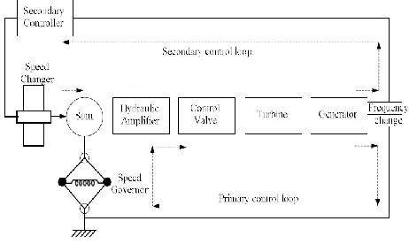
[image:2.612.335.556.196.339.2]Basically two types of inner control loops are there in LFC as shown in Figure 1. They are primary control and secondary control loop. The primary control loop adjusts the turbine power based on frequency change using control valve. This loop works much faster. The response time will be in seconds. The loop does only coarse on frequency. The secondary control loop eliminates the small error in frequency. It works after the control action of primary loop completes. It does the control action through speed changer until the frequency error becomes zero. It also controls the net power interchange between the power pool members.
Figure 1: Schematic diagram of LFC
III. MULTI-AREA POWER SYSTEM MODEL
In a two area interconnected power system, where the two areas are connected through tie lines, the control area are supplied by each area and the power flow is allowed by the tie lines among the areas. Whereas, the output frequencies of all the areas are affected due to a small change in load in any of the areas so as the tie line power flow are affected. So the transient situation information’s of all other areas are needed by the control system of each area to restore the pre defined values of tie line powers and area frequency. Each output frequency finds the information
about its own area and the tie line power deviation finds the information about the other areas.
Applying the swing equation of a synchronous machine to small perturbation, we have:
(1)
Or in terms of small deviation in speed
[image:2.612.46.277.396.534.2]
(2)
Figure 2: Mathematical modeling block diagram for generator
The speed-load characteristic of the composite load is given by:
(3)
The model for the turbine relates the changes in mechanical power output ΔPm to the changes in the steam valve position ΔPV.
(4)
The typical speed regulation of Governors is 5 to 6 percentage between no load and full load.
(5)
Or in s- domain
(6)
© 2017, IRJET | Impact Factor value: 6.171 | ISO 9001:2008 Certified Journal
| Page 1220
(7)
Overall block diagrams from earlier block diagrams for a single system as shown in Figure 3.
Figure 3: Mathematical Modeling of Block Diagram of single system consisting of Generator, Load, Prime Mover
and Governor
Figure 4 is a control block diagram for the ith area of a multi area power system. Although a power system is nonlinear and dynamic, the linearized model is permissible in the load frequency control problem because only small changes in load are expected during its normal operation. The largest part used control strategy in industry is P-I-D controller. It is used for various control problems such as automated systems or plants. A PID-Controller includes three different fundamentals, which is why it is at times called a three term controller. Proportional control, Integral control and Derivative control is the expansion of PID.
To meet up different design specifications for the system, PID control is able to put into operation. These can include the settling and rise time plus the accuracy and overshoot of the system step response. The three stipulations should be measured separately to realize the function of a feedback controller for PID.
IV. SIMULATION RESULT ANALYSIS
[image:3.612.341.553.104.237.2]In this section, simulations are given to demonstrate the validity and advantage of the proposed method. To prove the validity of the proposed method, a two-area LFC power system (1) with non-reheated turbines is considered, which rates of areas 1 and 2 are 1000 MW and 800 MW, respectively. The synchronizing coefficients T12 =T21 = 0.2 p.u. MW/Hz. The matlab block diagram is shown in Figure 4.
Figure 4: Simulink Block diagram
When t ≥ 3s, there are load demands ΔPL1 = ΔPL2 = 0.01 p.u.MW for the two Areas 1 and 2, respectively. It is necessary to point out that the overshoot and responding speed of ΔPtie,iare small and fast, respectively. Thus, the proposed method is effective and is shown in Figure 5.
Figure 5: Frequency response for LFC two-area with non-reheated turbine
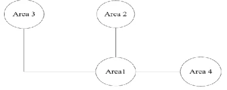
[image:3.612.51.277.172.284.2]To prove the advantages of the proposed method, a four area LFC system with non-reheated turbines containing four areas is considered, as shown in Figure 6. Areas 1, 2 and 3 are interconnected with each other, while Area 4 is only connected with Area 1.
Figure 6: Simplified diagram of a four-area power system
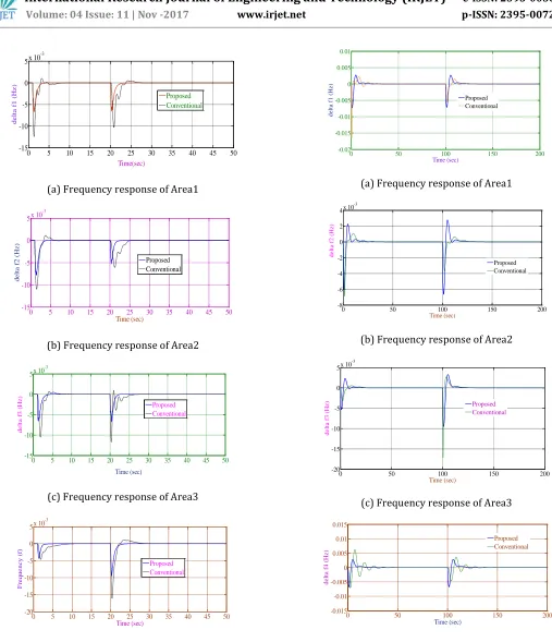
Figure 6 is simulated the response curves related to frequency is presented in Figure 7 & Figure 8.
FREQ1
FREQ2 P TIE
PM1
PM2 num(s)
s num(s) den(s)
num(s) den(s) 1
0.4s+1
1 0.44s+1
-K--K-
-K-1 0.06s+1 1 0.08s+1 PID
PID
0 5 10 15 20
-20 -15 -10 -5 0
x 10-3
Time (sec)
fr
eque
nc
y (
Hz
)
[image:3.612.344.554.343.430.2] [image:3.612.341.562.550.638.2]© 2017, IRJET | Impact Factor value: 6.171 | ISO 9001:2008 Certified Journal
| Page 1221
(a) Frequency response of Area1
(b) Frequency response of Area2
(c) Frequency response of Area3
(d) Frequency response of Area4
Figure 7: Frequency response curves of four area power system with non-reheated turbines
(a) Frequency response of Area1
(b) Frequency response of Area2
(c) Frequency response of Area3
[image:4.612.49.556.58.647.2](d) Frequency response of Area4
Figure 8: Frequency response curves of four area power system with reheated
0 5 10 15 20 25 30 35 40 45 50
-15 -10 -5 0 5x 10
-3 Time(sec) de lt a f 1 ( Hz ) Proposed Conventional
0 5 10 15 20 25 30 35 40 45 50
-15 -10 -5 0
5x 10
-3 Time (sec) de lt a f 2 ( Hz ) Proposed Conventional
0 5 10 15 20 25 30 35 40 45 50
-15 -10 -5 0 5x 10
-3 Time (sec) de lt a f 3 ( Hz ) Proposed Conventional
0 5 10 15 20 25 30 35 40 45 50
-20 -15 -10 -5 0
5x 10
-3 Time (sec) F re que nc y ( f) Proposed Conventional
0 50 100 150 200
-0.02 -0.015 -0.01 -0.005 0 0.005 0.01 Time (sec) de lt a f 1 ( Hz ) Proposed Conventional
0 50 100 150 200
-8 -6 -4 -2 0 2 4x 10
-3 Time (sec) de lt a f 2 ( Hz ) Proposed Conventional
0 50 100 150 200
-20 -15 -10 -5 0 5x 10
-3 Time (sec) de lt a f 3 ( Hz ) Proposed Conventional
0 50 100 150 200
© 2017, IRJET | Impact Factor value: 6.171 | ISO 9001:2008 Certified Journal
| Page 1222
V.
CONCLUSION
In this paper, a control method based on the PH system and cascade system for the multi-area LFC system is proposed. In short, compared with the traditional methods, the proposed method applies the structure and energy properties of multi-area LFC system to design a control law, which successfully works out the problem on how to effectively utilize the total tie-line power flow. Simulation results validate the effectiveness of the proposed solution under different operating modes.
REFERENCES
[1]. S. K. Pandey, S. R. Mohanty, and N. Kishor, “A
literature survey on load frequency control for conventional and distribution generation power systems,” Renew. Sustain. Energy Rev., vol. 25, pp. 318–334, 2013.
[2]. S.Ali Pourmousavi and M. Hashem Nehrir,
“Introducing dynamic demand response in the LFC model,” IEEE Trans. Power Syst., vol. 29, no. 4, pp. 1562–1571, Jul. 2014.
[3]. A. Safaei, H. Mahdinia Roodsari, and H. Askarian
Abyaneh, “Optimal load frequency control of an island small hydropower plant,” in Proc. 3rd Conf. Therm. Power Plants, 2011, pp. 1–6.
[4]. M. Rahmani and N. Sadati, “Hierarchical optimal
robust load-frequency control for power systems,” IET Gener., Transm. Distrib., vol. 6, no. 4, pp. 303– 312, 2012.
[5]. M. Farahani, S. Ganjefar, and M. Alizadeh, “PID
controller adjustment using chaotic optimization algorithm for multi-area load frequency control,” IET Control Theory Appl., vol. 16, no. 13, pp. 1984–1992, 2012.
[6]. W. Tan, “Unified tuning of PID load frequency
controller for power systems via IMC,” IEEE Trans. Power Syst., vol. 25, no. 1, pp. 341–350, Feb. 2010.
[7]. W. Tan, “Decentralized load frequency controller
analysis and tuning for multi-area power systems,” Energy Convers. Manag., vol. 52, no. 5, pp. 2015–2023, 2011.
[8]. S. Saxena and Y. Hote, “Load frequency control in
power systems via internal model control scheme and model-order reduction,” IEEE Trans. Power Sys., vol. 28, no. 3, pp. 2749–2757, Aug. 2013.
[9]. Y. Mi, Y. Fu, C. Wang, and P. Wang, “Decentralized
sliding mode load frequency control for multi-area power systems,” IEEE Trans. Power Syst., vol. 28, no. 4, pp. 4301–4309, Nov. 2013.
[10]. D. Rerkpreedapong, A. Hasanovic, and A. Feliachi,
“Robust load frequency control using genetic algorithms and linear matrix inequalities,” IEEE Trans. Power Syst., vol. 18, no. 2, pp. 855–861, May 2003.
[11]. A. Khodabakhshian and M. Edrisi, “A new robust
PID load frequency controller,” Control Eng. Pract., vol. 16, no. 9, pp. 1069–1080, 2008.
[12]. C. Ning, “Robust H∞ load-frequency control in
interconnected power systems,” IET Control Theory Appl., vol. 10, no. 1, pp. 67–75, 2016.
[13]. T. H. Mohamed, H. Bevrani, A. A. Hassan, and T.
Hiyama, “Decentralized model predictive based load frequency control in an interconnected power system,” Energy Convers. Manag., vol. 52, no. 2, pp. 1208–1214, 2011.
[14]. H. Yousef, K. AL-Kharusi, Mohammed H. Albadi,
and N. Hosseinzadeh, “Load frequency control of a multi-area power system: An adaptive fuzzy logic approach,” IEEE Trans. Power Syst., vol. 29, no. 4, pp. 1822–1830, Jul. 2014.
[15]. A. Ersdal, L. Imsland, and K. Uhlen, “Model
predictive load-frequency control,” IEEE Trans. Power Syst., vol. 31, no. 1, pp. 777–785, Jan. 2016.
[16]. H. Liu, Z. Hu, Y. Song, and J. Lin, “Decentralized
vehicle-to-grid control for primary frequency regulation considering charging demands,” IEEE Trans. Power Syst., vol. 28, no. 3, pp. 3480–3489, Aug. 2013.
[17]. Y. Mu, J. Wu, J. Ekanayake, N. Jenkins, and H. Jia,
© 2017, IRJET | Impact Factor value: 6.171 | ISO 9001:2008 Certified Journal
| Page 1223
[18]. T. Pham, H. Trinh, and L. Hien, “Load frequency
control of power systems with electric vehicles and diverse transmission links using distributed functional observers,” IEEE Trans. Smart Grid, vol. 7, no. 1, pp. 238–252, Jan. 2016.
[19]. H. Bevrani and P. Daneshmand, “Fuzzy
logic-based load-frequency control concerning high penetration of wind turbines,” IEEE Syst. J., vol. 6, no. 1, pp. 173–180, Mar. 2012.
[20]. H. Bevrani, P. Daneshmand, P. Babahajyani, Y.
Mitani, and T. Hiyama, “Intelligent LFC concerning high penetration of wind power: Synthesis and real-time application,” IEEE Trans. Sustain. Energy, vol. 5, no. 2, pp. 655–662, Apr. 2013.
BIOGRAPHY:
Mr. N. Narasimhulu has completed his professional career of education in B. Tech (EEE) from JNTU Hyderabad in the year 2003. He obtained M. Tech degree from JNTU, HYDERABAD, in year 2008. He is pursuing Ph. D in the area of power system in JNTU Anantapuramu. He has worked as Assistant Professor from 2003-2008 and at present working as an Associate Professor and Head of the EEE Department in Srikrishna Devaraya Engineering College, Gooty of Anantapuramu district (AP). He is a life member of ISTE, FIE, IEEE. His areas of interests include Electrical Power Systems, Electrical Circuits and Control Systems
M.GANESH BABU has completed his professional career of education in B.E (EEE) at Acharya Institute of Technology,Bangalore and pursuing M.Tech from Sri Krishnadevaraya engineering college, Gooty, Anantapur(AP). He is interested in Electrical Power Engineering .
K.SWATHI has 3 years experience in teaching in graduate and post graduate level and at present she is working as an Assistant professor in the department of EEE ,Sri Krishna devaraya Engineering College, Gooty, AP, India.
Dr. R. RAMACHANDRA has completed his professional career of education in B. Tech (MECHANICAL) from JNTU Hyderabad. He obtained M. Tech degree from JNTU, Hyderabad. He obtained Ph. D degree from JNTU, Hyderabad At present working as Professor and Principal in Sri krishna Devaraya Engineering College, Gooty of Anantapuramu district (AP).