International Journal of Emerging Technology and Advanced Engineering
Website: www.ijetae.com (ISSN 2250-2459, ISO 9001:2008 Certified Journal, Volume 4, Issue 1, January 2014)
566
Design of Multiband Meander-Line Antennas and Their
Performance Analysis
Susmita Ghosh
Department of Electrical and Electronic Engineering, American International University-Bangladesh (AIUB), Banani, Dhaka-1213, Bangladesh.
Abstract—In this paper, multiband meander-line antennas have been proposed which are of folded type meander–line antennas. The simulation performed in this paper used CST_STUDIO_2012. Far-field response, efficiency, gain, directivity and reflection coefficients have been chosen as performance factors for measuring antenna quality. Total four models have been represented in this paper starting from single band resonator then dual band resonator then triple band resonator and then tetra band resonator. All antennas with different lengths, turn number as well as fold number but having same geometrical spacing and width have been designed and simulated. In the very first design, the antenna is a single band resonator but after increasing the turn number, using strip lines and increasing the length of a specific turn, the number of resonating frequency increases. This paper work represents the continuous improvement in the performance of the antenna in terms of resonance, reflection coefficient, gain and directivity. This paper work represents total four types of folded meander-line antennas that are able to operate in the LTE/GSM1800, PCS/ UMTS/ WLAN/ LTE2400, L band (1-2 GHz) and S band (2-4 GHz).
Keywords—Folded type meander-line antenna, improved reflection coefficient, LTE networks, strip line and single to tetra band resonance.
I. INTRODUCTION
The invention of new technologies in communication system and their widespread uses as well as the demand for the high speed communication systems, have made it mandatory for the engineers to design cheaper and simpler communication equipment. Some of the most recognized communication fields are WLAN system, GSM/EDGE, UMTS/HSPA & 4G LTE networks [1]. Antenna is an inseparable part of these networks. Meander-line antenna is the one of the efficient antennas that can be used in the design of these applications. A meander antenna is an extension of the basic folded antenna and frequencies much lower than resonances of a single element antenna of equal length. Radiation efficiency of meander line antenna is good as compare to conventional half and quarter wavelength antennas [3].
In some designs the ground plane is bonded with substrate from opposite side and in some designs it is different. In this paper the ground plane is on the radiating side of the substrate [4].
Classic meander-line antenna has low efficiency in some aspects such as operation in only one resonant frequency i.e. single band. But the proposed antennas in this paper have overcome this limitation.
The very first proposed antenna is a single band antenna with a single strip line but after adding another strip line, one more resonance increases, i.e. the antenna becomes a dual-band antenna [2].
Another resonance in increased after increasing the turn numbers and antenna becomes triple–band antenna and finally by increasing the length of third turn, the tetra-band antenna is achieved.
II. ANTENNA DESIGN
The antenna design in this project is done with CST STUDIO SUITE 2012 for the 3D layout. It is used to simulate each antenna model including S11 reflection coefficients, far-field response, radiation efficiency, gain and directivity for studying characteristic parameter of antenna, the antenna designs, and measure results.
A.Common Parameters of All Designs
International Journal of Emerging Technology and Advanced Engineering
Website: www.ijetae.com (ISSN 2250-2459, ISO 9001:2008 Certified Journal, Volume 4, Issue 1, January 2014)
567
B. Single Band Antenna- “Design A”The first proposed antenna is of a single turn, singly folded, with physical dimension of 159mm length, 10 mm width and 2 mm height. The front view including strip line, side view, the back plane including capacitive coupling and the feed point are being shown in the Figure 1.
(A) (B)
[image:2.612.46.288.213.402.2](C) (D)
Figure 1: Orientation of single band meander-line antenna - (A) Top view, (B) Side view, (C) Feed point and (D) Back plane.
Simulation Results of Single Band Antenna- “Design A”: After running the simulation on antenna ―Design A‖ by ―CST STUDIO SUITE‖, it’s found that the antenna has only one resonant frequency with maximum resonance and that is 1.1352 GHz which can be verified from Figure 2.
Figure 2: The antenna reflection coefficient expressed in dB.
[image:2.612.327.563.295.455.2]Figure 3 shows the Far-field response of ―Design A‖ at resonant frequency with maximum resonance in polar plotting.
Figure 3: Far-field Response of ―Design A‖ at 1.1352 GHz. TABLE I
SUMMARIZED SIMULATED RESULTS OF ―DESIGN A‖
F
re
q
u
en
cy
(GH
z)
Re
flec
ti
o
n
c
o
efficie
n
t
(d
B)
Eff
icie
n
cy
(%
)
Ga
in
(d
B)
Dire
cti
v
it
y
(
d
Bi)
M
ain
l
o
b
e
m
ag
n
it
u
d
e
(d
B)
[P
h
i=0
º]
1.1352 -11.7072 95.39 2.971 2.872 3
From the TABLE I, it’s been seen that this single band meander-line antenna has only one resonating frequency, which falls in L band, and it can be used for Global Positioning System which is carried by L band.
C. Dual Band Antenna- “Design B”
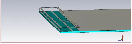
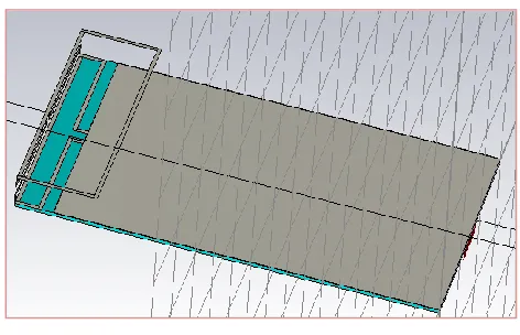
The second proposed antenna is similar as ―Design A‖ with single turn, singly folded, with physical dimension of 159mm length, 10 mm width and 2 mm height. But in this antenna an extra strip line is being added, the strip line is being added just at the bending end of the first fold. Due to the addition of this strip line another resonance frequency is achieved. Figure 4 shows the orientation of the antenna including the strip line.
[image:2.612.55.280.498.606.2] [image:2.612.338.559.622.697.2]International Journal of Emerging Technology and Advanced Engineering
Website: www.ijetae.com (ISSN 2250-2459, ISO 9001:2008 Certified Journal, Volume 4, Issue 1, January 2014)
568
Simulation Results ofDual Band Antenna- “Design B”: [image:3.612.336.559.110.471.2]Maintaining the same feed point as ―Design A‖, simulation is run on ―Design B‖ and the resulting reflection coefficients after the simulation of ―Design B‖ show that the antenna has two resonanting frequencies, one at 1.1114 GHz and another one is at 2.496 GHz i.e. the antenna is a dual band antenna. The simulated reflection coefficient is shown in Figure 5.
Figure 5: The antenna reflection coefficient expressed in dB.
Figure 6 shows the Far-field response of ―Design B‖ at resonant frequency 1.1114 GHz with maximum resonance in polar plotting.
[image:3.612.341.561.141.279.2]
Figure 6: Far-field Response of ―Design B‖ at 1.1114 GHz.
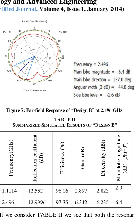
Figure 7 shows the Far-field response of ―Design B‖ at resonant frequency 2.496 GHz with maximum resonance in polar plotting.
[image:3.612.50.283.237.345.2]
Figure 7: Far-field Response of ―Design B‖ at 2.496 GHz. TABLE II
SUMMARIZED SIMULATED RESULTS OF ―DESIGN B‖
F
re
q
u
en
cy
(GH
z)
Re
flec
ti
o
n
c
o
efficie
n
t
(d
B)
Eff
icie
n
cy
(%
)
Ga
in
(d
B)
Dire
cti
v
it
y
(
d
Bi)
M
ain
l
o
b
e
m
ag
n
it
u
d
e
(d
B)
[P
h
i=0
º]
1.1114 -12.552 96.06 2.897 2.823 2.9
2.496 -12.9996 97.35 6.342 6.235 6.4
[image:3.612.332.557.278.452.2] [image:3.612.52.276.413.536.2]International Journal of Emerging Technology and Advanced Engineering
Website: www.ijetae.com (ISSN 2250-2459, ISO 9001:2008 Certified Journal, Volume 4, Issue 1, January 2014)
569
D. Triple Band Antenna- “Design C” [image:4.612.332.558.151.270.2]In this design the turn number of antenna has been increased but the antenna is singly folded. The physical length of the antenna is 280 mm, width is 10 mm and height is 6.5 mm. Due to the increase of the turn number, frequency response is also increased than the second design. This antenna is able to operate at three frequency band. The feed size and position is same as the previous design. The antenna orientation is shown in Figure 8.
Figure 8: Orientation of triple band meander-line antenna
Simulation Results of Triple Band Antenna- “Design C”: The resulting reflection coefficients in Figure 9 after the simulation of ―Design C‖ show that the antenna operates at three resonant frequencies 1.8854 GHz, 2.242 GHz and 2.4402 GHz i.e. the antenna is a triple band antenna.
Figure 9: The antenna reflection coefficient expressed in dB.
Figure 10 shows the Far-field response of ―Design C‖ at resonant frequency 1.8854 GHz with maximum resonance in polar plotting.
Figure 10: Far-field Response of ―Design C‖ at 1.8854 GHz.
Figure 11 shows the Far-field response of ―Design C‖ at resonant frequency 2.242 GHz with maximum resonance in polar plotting.
[image:4.612.56.277.249.355.2]
Figure 11: Far-field Response of ―Design C‖ at 2.242 GHz.
Figure 12 shows the Far-field response of ―Design C‖ at resonant frequency 2.4402 GHz with maximum resonance in polar plotting.
[image:4.612.334.562.336.454.2][image:4.612.58.277.440.559.2] [image:4.612.334.556.535.640.2]
International Journal of Emerging Technology and Advanced Engineering
Website: www.ijetae.com (ISSN 2250-2459, ISO 9001:2008 Certified Journal, Volume 4, Issue 1, January 2014)
570
TABLE III
SUMMARIZED SIMULATED RESULTS OF ―DESIGN C‖
F
re
q
u
en
cy
(GH
z)
Re
flec
ti
o
n
c
o
efficie
n
t
(d
B)
Eff
icie
n
cy
(%
)
Ga
in
(d
B)
Dire
cti
v
it
y
(
d
Bi)
M
ain
l
o
b
e
m
ag
n
it
u
d
e
(d
B)
[P
h
i=0
º]
1.8854 -32.657 100 5.281 5.167 4.9
2.242 -14.255 90.79 3.201 3.455 3.1
2.4402 -38.706 100 4.91 4.787 4.8
Considering all the parameters in TABLE III it can be stated that, two resonators, 1.8854 GHz and 2.4402 GHz have enough low return losses, one has -32.657 dB and another has -38.706 dB. Gain and main lobe magnitude of these two resonators are also good enough whereas these parameters of the other resonator is not that much high. But all the three resonances have got significant applications, like 1.8854 GHz resonator can be used in GSM/ 1800 MHz communication systems and also it falls in L band. Whereas the other two fall in S band and can be used in Digital Audio Radio Satellite, Mobile Satellite Service Ancillary, Terrestrial Components, Direct-to-Home satellite television and unlicensed band communications.
E. Tetra Band Antenna- “Design D”
[image:5.612.326.562.133.285.2]In this design the turn number of antenna has been kept to double turn as in the ―Design C‖ with single folding, which is shown in Figure 8. Total length of the antenna has been increased by increasing the length of second turn. Due to increasing the length of second turn, frequency responses of antenna has been improved. This antenna is able to operate at three frequency bands. The feed size and position is same as the previous design. The antenna orientation is being shown in Figure 13.
Figure 13: Orientation of tetra band meander-line antenna
Simulation Results of Tetra Band Antenna- “Design D”:
[image:5.612.51.288.146.295.2]The resulting reflection coefficients in Figure 14 after the simulation of ―Design D‖ show that the antenna operates at four resonant frequencies, 1.8772 GHz, 2.0816 GHz, 2.2664 GHz and 2.3981 GHz i.e. the antenna is a tetra band antenna. Moreover, return loss of a range of frequencies, around 2.2 GHz to 2.45 GHz is below -10 dB.
Figure 14: The antenna reflection coefficient expressed in dB.
Figure 15 shows the Far-field response of ―Design D‖ at resonant frequency 1.8772 GHz with maximum resonance in polar plotting.
[image:5.612.333.557.386.496.2] [image:5.612.330.563.556.671.2]International Journal of Emerging Technology and Advanced Engineering
Website: www.ijetae.com (ISSN 2250-2459, ISO 9001:2008 Certified Journal, Volume 4, Issue 1, January 2014)
[image:6.612.329.569.131.308.2]571
Figure 16 shows the Far-field response of ―Design D‖ at resonant frequency 2.0816 GHz with maximum resonance in polar plotting. [image:6.612.37.291.182.296.2]
Figure 16: Far-field Response of ―Design D‖ at 2.0816 GHz.
[image:6.612.53.282.359.480.2]Figure 17 shows the Far-field response of ―Design D‖ at resonant frequency 2.2664 GHz with maximum resonance in polar plotting.
Figure 17: Far-field Response of ―Design D‖ at 2.2664 GHz.
[image:6.612.52.287.546.663.2]Figure 18 shows the Far-field response of ―Design D‖ at resonant frequency 2.3981 GHz with maximum resonance in polar plotting.
Figure 18: Farfield Response of ―Design D‖ at 2.3981 GHz.
TABLE IV
SUMMARIZED SIMULATED RESULTS OF ―DESIGN D‖
Considering all the parameters from TABLE IV it can be stated that except one resonant frequency,2.0816 GHz, all other resonant frequencies have good return losses, whereas the gain of all frequencies except 2.2664 GHz is also uniform, around 5 dB. The main lobe magnitude is highest at 2.3981 GHZ. The first resonant frequency, 1.8772 GHz falls in L band where its application can be found in Global Positioning system, as well as it can be included in GSM/1800 MHz communication system. The other three frequencies lie in S band, which can be used in satellite, radar and unlicensed band communication systems.
III. CONCLUSION
This paper work has been started with a goal to design an antenna which will be able to operate at multiple resonant frequencies. All the designed antennas in this work are of fixed length 100mm and width 60mm, i.e. all the antennas can be easily inserted in a cellular phone structure. Although this paper work started with a single band resonator but gradually it has been finished with a tetra band resonator. Initially in ―Design A‖ a folded loop meander-line antenna with a single strip line, single turn is being designed which operates at a single resonant frequency. The maximum resonating frequency is 1.1352 GHz. In ―Design B‖, another strip line is added so the antenna becomes able to operate at double resonant frequency [2]. The maximum resonating frequencies are 1.1114 GHz and 2.496 GHz. In ―Design C‖, number of turn is being increased with two strip lines and the resonating frequencies get increased to three.
F
re
q
u
en
cy
(GH
z)
Re
flec
ti
o
n
c
o
efficie
n
t
(d
B)
Eff
icie
n
cy
(%
)
Ga
in
(d
B)
Dire
cti
v
it
y
(
d
Bi)
M
ain
l
o
b
e
m
ag
n
it
u
d
e
(d
B)
[P
h
i=0
º]
International Journal of Emerging Technology and Advanced Engineering
Website: www.ijetae.com (ISSN 2250-2459, ISO 9001:2008 Certified Journal, Volume 4, Issue 1, January 2014)
572
The maximum resonating frequencies are 1.8854 GHz, 2.242 GHz and 2.4402 GHz. In the same design if we increase the length of first fold, the design becomes a tetra band resonator, ―Design D‖, with four resonating frequencies where the maximum resonating frequencies are 1.8772 GHz, 2.0816 GHz, 2.2664 GHz and 2.3981 GHz.REFERENCES
[1] Sesia S., I. Toufik, and M. Baker, ―LTE -The UMTS Long Term Evolution: From Theory to Practice‖, Wiley, Chichester, UK, 2009. [2] Wong K. L. and W. Y. Chen, ―Small-size printed loo-type antenna
integrated with two stacked coupled-fed shorted strip monopoles for eight-band LTE/GSM/UMTS operation in the mobile," Microwave
and Optical Technology Letters, Vol. 52, No. 7, 1471-1476, Jul. 2010.
[3] V.B. Ambhore and A.P.Dhande, ―An Overview on Properties, Parameter Consideration And Design of Meandering Antenna‖. Tavel, P. 2007 Modeling and Simulation Design. AK Peters Ltd. [4] Balanis. C. A. (1997). Antenna Theory: Analysis & Design (pp.
245-267,309-312, 467-468, 723-729,772-773). 2nd edition- John Wiley & Sons. Inc. (0-471-59268-4).Forman, G. 2003. An extensive empirical study of feature selection metrics for text classification. J. Mach. Learn. Res. 3 (Mar. 2003), 1289-1305.