International Journal of Emerging Technology and Advanced Engineering
Website: www.ijetae.com (ISSN 2250-2459, ISO 9001:2008 Certified Journal, Volume 8, Issue 3, March 2018)
99
Model Study for In-Situ Stabilization of Expansive Soil
Deposit by Diffusion of Calcium Chloride Solution
Sangita P. Lajurkar
1, Yadav S. Golait
2, Shantanu R. Khandeshwar
31Research Scholar, 3Professor, Y.C.C.E, RTMN University, India 2Ex-Professor, R.C.O.E.M, RTMN University, India
Abstract— Lightly loaded structures founded on expansive soil deposits exhibit various distresses, deformations and damages, sometimes even collapse of the structures also, due to its swell-shrink nature and low bearing capacity. In this paper, the bad geological characteristics and the huge disaster caused by expansive soil is elaborated, as well as various measures to control the disaster caused due to distressed structure founded on them along with the new innovative technique of rehabilitation of expansive soil by chemical diffusion technique. In field possible method of application of chemical solution is through ponding or bore hole for in-situ ground improvement. The paper highlights result of the model study carried out on relatively large models of soil simulating the field situation of ground improvement by ponding and bore-holes by diffusion technique using 2% calcium chloride solution. Test results are analyzed considering effect on strength improvement and swell reduction. From the test result it is revealed that the ground improvement by diffusion of chemical solution through bore-hole covered 1.5-2.0 m distance in lateral radial direction and improves strength up to 60%-70% and reduces swelling up to 75% whereas in case of ponding, ground improvement up to 1m depth in vertical downward direction is possible. Comparatively exceptional results had been obtained through holes bored up to a suitable depth.
Keywords— Expansive soil deposit, Improvement by Diffusion technique, Calcium chloride, Swelling behavior, UCS.
I. INTRODUCTION
Natural expansive soils have been found in many places around the world. The countries that are facing problems with expansive soils are Africa, Australia, South America, United States, Canada, China, Israel, India, and Egypt. These types of soils are generally found in arid and semi-arid regions of the world and are considered as a potential natural hazard, which if not treated well can cause extensive damages not only to the structures built upon them but also can cause loss of human life [1], [2].
The six major natural hazards are earthquakes, landslides, expansive soils, hurricane tornado, and flood. A study points out that expansive soils tie with hurricane wind/storm surge second place among America's most destructive natural hazards in terms of dollar losses [3].
According to the study, it was projected that the annual cost of damage to the civil engineering structures is estimated at £150 million in the UK, $1000 million in the USA and many billions of pounds worldwide [4]. By the year 2000, losses due to expansive soil exceed 4.5 billion dollars annually. In 2013 ITRC reported that soil movement in the UK has a financial impact of between £300-500 million per annum [5]. In India too, tens of millions of rupees are spent on repairs, maintenance and rehabilitation of damaged structures every year.
II. DAMAGES TO STRUCTURES
Structure constructed in expansive soil suffer from various types of damages due to up lift forces and settlement caused by the expansive soils such as
1. Severe cracking in light single and double storied buildings.
2. Cracking and distortions in road pavements. 3. Shear cracks in earth dam cores.
4. Slides in canal lining and heaving of canal bottom. 5. Cracks and movements in retaining wall structures. 6. Distortions and disruptions in utility and service Lines
like Underground Conduits, Ducts, Pipe Lines etc.
III. FOUNDATION PRACTICES ON EXPANSIVE SOILS
At different times, various precautionary measuresand methods of constructing foundations on expansive soil have been suggested. As a result of unending research on this aspect in many countries, new and better techniques of foundation construction in these soils have been evolved. These measures can be broadly classified into the following categories:
A. Replacement of Expansive Soil
Replacing expansive soil layer over the entire area to be occupied by a building or structure down to a firm and stable stratum with granular soil [1].
B. Design of Structures and Foundations to Withstand Swelling
International Journal of Emerging Technology and Advanced Engineering
Website: www.ijetae.com (ISSN 2250-2459, ISO 9001:2008 Certified Journal, Volume 8, Issue 3, March 2018)
100 Strong and Rigid Structures:
The structures are made strong and rigid to withstand heave; designing the structure as a rigid unit by adequately reinforcing the entire brickwork or by constructing RCC superstructure on raft foundation. Providing RCC bands (beams) at plinth and lintel levels in the masonry of a building. Vertical reinforcements connecting the bands at different levels have also been proposed. Increase the loading intensity on the foundation soil to counteract the swelling pressures.
Flexible Structures:
Making provision to absorb soil movements occurring below the foundation by partially filling the foundation trenches with material like rubber, sand etc., or by providing a flexible type of structure such as CNS or CSS layer [2],[6],. Vertical inclusions in the ground in the form of geo-piles to counteract heave and stone columns for improving the bearing capacity also recommended recently [8].
Isolating Foundations:
Isolating the foundation structure from the surrounding expansive soil by filling in the trenches compacted sand, gravel or Murom below and on sides of foundation; and thus forming the isolating cushions. In this case, deep foundations such as drilled piers, belled piers, under reamed piles and granular pile anchors (GPAs) are constructed to isolate the foundation from the swelling effect of the soil [7]-[8].
C. Modification of the Expansive Soil
The characteristics of an expansive soil can be modified to reduce its swelling potential. Some of the commonly used methods are heave of expansive soils is known to decrease substantially when the soil is com-pacted to a lower unit weight on the high side of the optimum water content, prewetting by ponding or submerging an area, use of drainage system and moisture barriers, use of in-situ reinforcement, use of geotextiles, grouting, heat stabilization, electrical Stabilization and stabilization of soil.
Stabilization of Soil:
As defined by McGraw-Hill Dictionary of
Architecture and Construction (2003), soil stabilization is a chemical or mechanical treatment designed to increase or maintain the stability of a soil mass or otherwise to improve its engineering properties by increasing its shear strength, reducing its compressibility, or decreasing its tendency to absorb water.
Methods of Stabilization:
Numerous methods by which soils can be stabilized are categories into mechanical stabilization, chemical stabilization and use a combination of these two methods.
In mechanical stabilization method, the grain size gradation of the site soil is altered. Where the site soil is predominantly gravel (say, from 75 mm down to 1 mm) binder material is added. Binder is defined as material passing either the 0.425 mm or 0.150 mm sieve. The binder is used to fill the voids and usually adds mass cohesion. Where the soil is predominantly cohesive granular soil is imported and blended with the site soil.
Chemical stabilization is the addition of stabilization chemical additives to promote chemical reactions. This method is most effective and commonly used method for enhancing the engineering behavior of soil with respect to reduction in swelling and improving in strength. The present research work is in the category of innovative technique of chemical soil stabilization [9]-[11].
IV. PRINCIPLE AND BASIC CONCEPT
It is realized that the ‗In-situ‘ expansive clay has certain water imbibing capacity of varying magnitude depending on its initial water content. Expansive clay with its electrochemical activity exhibits certain osmotic pressure and water suction characteristics. Water thus diffuses into the soil mass in a definite zone surrounding the point of water supply source. It is thought that water-soluble chemical may also enter into the soil body if it is diffused into it. The diffused chemical solution after entering into the soil mass may interact with the electrochemically active clay particles of expansive soil thereby altering its characteristics with respect to strength, compressibility, stiffness and swell-shrink nature. It is of great interest to reveal to a certain reasonable extent the various aspects of the effects of diffused chemical solution on native expansive soil mass. The present study involves these considerations.
International Journal of Emerging Technology and Advanced Engineering
Website: www.ijetae.com (ISSN 2250-2459, ISO 9001:2008 Certified Journal, Volume 8, Issue 3, March 2018)
101 In the case of ponding method a specified size of pond depending on the area to be stabilized can be prepared and flooded with the chemical solution so that the chemical solution moves in vertical downward direction and stabilize the soil mass. In order to study the effectiveness and practicability of both the methods in actual ground conditions and to assess the extent of influenced zone of stabilization by both the methods, the lab investigations are carried out on large scale models. It is worthwhile at this stage because the studies with respect to diffusion of chemical in vertical direction over a large depth and also diffusion in radial horizontal direction on substantially large scale model it has been carried out anywhere. Detailplanning to studythe effect of diffusion at various distances either in vertical and horizontal was done. For this care has to be taken to simulate the field condition in the model study.
The work is planned to be carried out with the following main aims and objectives:
Effect of different methods of application of chemical solution i.e. vertical diffusion by ponding and horizontal diffusion through boreholes.
Evaluation of the extent of diffusion in vertical and lateral directions from the source.
V. MATERIAL USED
A. Soil:
In India, the swelling soils which cover about 20% of the total area of the country are colloquially called as black cotton soils because of their black color and fertility to grow cotton crop in abundance. This black cotton soil was collected from the site in the neighborhood of Nagpur city of India by the method of disturbed sampling after removing the top layer of soil upto1m depth. Its basic properties are: liquid limit wL =
58.80%, plastic limit wp= 33.16% Ip = 25.64%, sand
content = 9.29%, clay content = 60.53% and silt content = 30.18%, Free swell ratio (FSR) = 2.522, Free swell index = 39% and specific gravity = 2.71.
B. Chemicals:
Commercially available calcium chloride (CaCl2) was
selected for the study. It consisted of 72.79% calcium chloride (CaCl2), <0.1% magnesium chloride (MgCl2)
and 27.21% water (H2O).
VI. MODEL STUDY WITH RESPECT TO PRACTICAL
APPLICATION
Large-scale model study exhibiting field condition of in-situ ground improvement by chemical diffusion through bore hole and ponding in the laboratory with a high degree of precision and controlled monitoring was carried out to access the practicability and degree of success of these methods.
From the results of previous laboratory investigation and review of literature 2% concentration of the commercial-grade CaCl2 solution was selected for model
study [16].
A. Bore Hole Method
Two moulds of cross section 30cmX30cm and length 2m was design and fabricated. For swelling measurement dial gauges were fixed at 0.5 m, 1m, 1.5m and 1.9m distance from the source with help of specially designed hangers to evaluate the extent of diffusion in a lateral direction as shown in Fig. 1. Prepared wet soil was filled having water content approximately 50-60 percent (midway between its plastic limit wp and liquid limit wL)
[image:3.595.334.528.544.686.2]layer wise in the mould by giving light compaction to avoid air pocket and the soil was allowed to settle by its own. These so prepared soil beds were air dried for a period of two months. When the water content of the soil bed reached up to in between state plastic and shrinkage limit value, the soil was considered as near-natural dry condition respectively of field soil deposit and ready for further testing. Due to shrinking the volume of soil bed reduces to 27.5cmX27.5cm in cross section and 1.9m in length at the end of two months. The model test assembly ensured laterally confined state of soil bed at all stages. There after taking all the cares water was filled in one model tank and 2% calcium chloride solution in another one and allow it to diffuse laterally in soil bed. The increase in height of soil bed (∆h) with respect to its initial height (h) was observed from the dial gauge readings during 45 days of diffusion period for both water and calcium chloride solution. Undisturbed samples were collected from the same location where the swelling was observed and tested for UCS. The final water content of the sample was then determined for each location.
Fig. 1 Model of diffusion through borehole in soil bed CaCl2
Solution
International Journal of Emerging Technology and Advanced Engineering
Website: www.ijetae.com (ISSN 2250-2459, ISO 9001:2008 Certified Journal, Volume 8, Issue 3, March 2018)
[image:4.595.316.524.132.374.2]102 Fig. 2 Schematic diagram showing Experimental Setup of Model of
Bore Hole method
B. Ponding
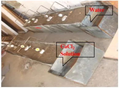
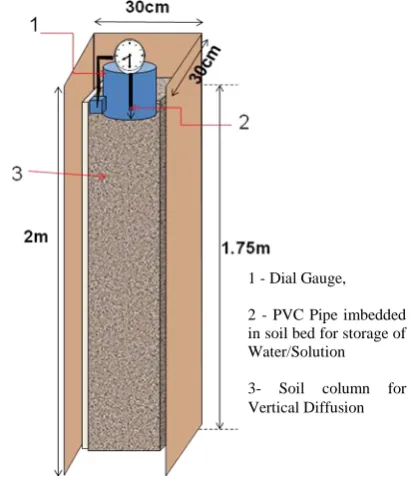
For ponding method two mould of cross-section 30cmx30cm and 2m height were assembled with four panels of MS sheet with adjustable screw arrangement (during the shrinking process the panels can be adjusted with soil specimen), one is for diffusion of water and another one is for 2% calcium chloride solution for comparison. Prepared wet soil filled in column mould. These so prepared wet soil columns allowed drying for three months to achieve near-natural dry condition respectively of field soil deposit. Due to shrinking the volume of soil reduces its size and become 28 cm X 28cm in cross section and 1.75m in length. For storage and supply of diffusion fluid PVC pipe of size 15cm diameter and17cm height was embedded centrally on prepared dry soil specimen, it act as a pond as shown in Fig. 3. This ideal model soil assembly of vertical diffusion through ponding was used by taking care of lateral confinement and vertical diffusion through soil mass only at all the stages.
[image:4.595.54.274.136.305.2]Dial gauge was placed at top of soil column with help of specially designed assembly for swell measurement as shown in Fig. 3, Fig. 4. After completion of 45 days of diffusion process, undisturbed samples were then collected at the different location for UCS and final water content determination.
Fig. 3 Swell measurement arrangement
Fig. 4 Schematic diagram showing Experimental Setup of Model of ponding method
VII. RESULTS AND DISCUSSION
From the previous study carried out in the laboratory, the promising performance of CaCl2 in clay stabilization was observed and its efficacy for ground modification was studied by conducting large scale model study of soil modification through bore hole and by ponding method. The swelling behavior of soil bed was then observed during 45 days of diffusion process for water and 2% CaCl2 solution through the soil specimen by ponding and also through boreholes and UCS test was then conducted on undisturbed soil sample collected from different locations. The results of the model study are presented below.
A. Borehole method
It can be observed from Table 1 that model soil at initial water content (wi) 11.94% finally attained almost
same water content with w 26%, 24%, 24% at distance
0.5m, 1.0m and 1.5m during lateral diffusion of water through the borehole. But at the 1.9m distance the final
water content is less (31%) with w 19% indicating that
the spread of water to reach the soil near saturation state due to lateral diffusion is possible up to 1.5 m only. The surety of spreading beyond 1.5m becomes less. After completion of 45 days of diffusion, the resulting maximum swelling strain as expressed by ∆h/h values are 19.11%, 18.25%, 17.863 and 15.817% at 0.5m, 1m, 1.5 and 1.9m respectively. As compared to this the diffusion of 2% CaCl2 solutions caused much smaller values of ∆w and ∆h/h.
1- Water/Solution 2- Filter Paper + Net 3- Dial Gauge
4- Filling of Cement Slurry 5- Soil Bed for Diffusion 6- Sand Cushion
7- Clamp for Fixing Dial Gauge
1 - Dial Gauge,
2 - PVC Pipe imbedded in soil bed for storage of Water/Solution
[image:4.595.109.219.642.724.2]International Journal of Emerging Technology and Advanced Engineering
Website: www.ijetae.com (ISSN 2250-2459, ISO 9001:2008 Certified Journal, Volume 8, Issue 3, March 2018)
[image:5.595.57.255.131.286.2]103 Fig. 5 Swelling behavior of soil at different location during lateral
[image:5.595.318.536.219.581.2]diffusion through bore hole
Fig. 6 Stress- strain behavior of soil at different location during lateral diffusion through bore hole
The unconfined compressive strength of undisturbed samples collected from CaCl2 treated and untreated soil bed is presented in Table 1. The substantial improvement in UCS values can be observed for CaCl2 treated soil
samples, the improvement considering the UCS of sample diffused by water as the base. The increase in UCS was observed as 60%-70% for treatment with 2% CaCl2 solution.
B. Ponding
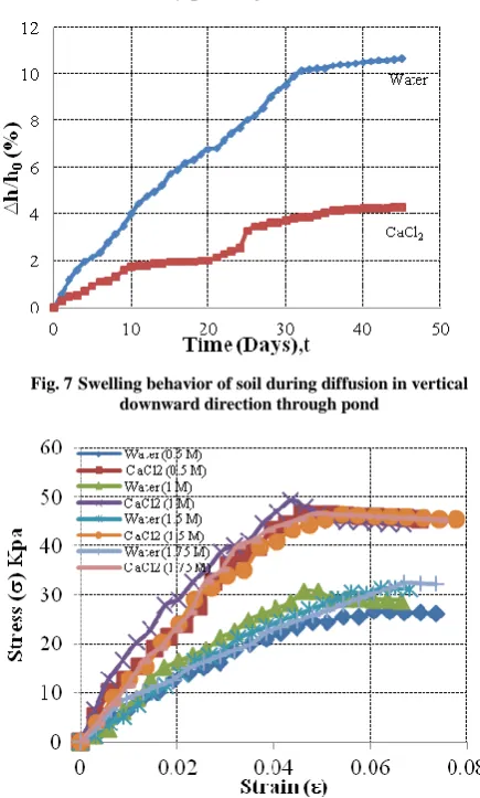
The results obtained from this part of the study are presented in Table 2 and Figs 7 and 8.
Percent swell vs time plots Fig. 7 shows the swelling behavior of soil column for water and 2% CaCl2 solution
by ponding method. From the results reduction in swelling and improvement in UCS for treated soil compared with untreated soil can be observed. The maximum reduction in swelling up to 60% and increase in UCS up to 60% was noted in the case of diffusion of 2% CaCl2 solution by ponding method.
Fig. 7 Swelling behavior of soil during diffusion in vertical downward direction through pond
[image:5.595.320.525.230.394.2] [image:5.595.63.267.323.464.2]International Journal of Emerging Technology and Advanced Engineering
Website: www.ijetae.com (ISSN 2250-2459, ISO 9001:2008 Certified Journal, Volume 8, Issue 3, March 2018)
104 TABLE 1
EFFECT OF LATERAL DIFFUSION OF 2%CACL2 SOLUTION THROUGH BORE- HOLE ON SWELLING STRAIN AND UCS OF SOIL
Parameters
Distance from source
Initial water content (wi % )
Final water (wf %)
Change in water content (w = wf - wi)
Swelling strain (h/h%)
Reduction in swelling strain (RSS %) UCS (kPa) Percentage increase in UCS (PSI)
0.5M
Water 11.94 38 26 19.11
69.46
31.06
63.68
CaCl2 32 20 5.84 50.84
1.0M
Water 36 24 18.25
71.44
34.01
61.82
CaCl2 32 20 5.21 55.03
1.5M
Water 36 24 17.86
72.20
33.25
67.50
CaCl2 32 20 4.97 65.70
1.9M
Water 31 19 15.82
75.74
33.28
63.36
CaCl2 27 15 3.84 54.37
TABLE 2
EFFECT OF VERTICAL DOWNWARD DIFFUSION OF 2%CACL2 SOLUTION BY POND ON SWELLING STRAIN AND UCS OF SOIL
Parameters Distance from source Initial water content before diffusion (wi % )
Final water after diffusion
(wf %)
Change in water content (w = wf - wi)
UCS (kPa) Percentage
increase in UCS (PSI)
0.5M
Water
14.27
36 22 26.66
62.65
CaCl2 27 13 43.37
1.0M
Water 35 21 30.77
60.46
CaCl2 32 20 49.37
1.5M
Water 36 24 31.47
45.92
CaCl2 32 20 45.91
1.9M
Water 31 19 32.50
43.27
CaCl2 27 15 46.57
VIII. CONCLUSION
The following conclusions are drawn
[1] 70%-75% reduction in swelling and 60%-70%
improvement in UCS was observed in a case of lateral horizontal diffusion of 2% CaCl2 solution through
borehole.
[2] 60 % reduction in swelling and 40%-65%
improvement in UCS was observed in a case of vertical diffusion of 2% CaCl2 solution by ponding
method.
[3] The beneficial influence of CaCl2 is almost the
same in the ponding and borehole methods up to 1m. Beyond 1m improvement in UCS is less in case of ponding comparing to bore hole method, indicating that the spread of chemical solution is similar in both methods up to 1m and thereafter rate of spreading is reduces in a case of ponding.
REFERENCES
[1] Ranjan, G. and Rao A. S. R. 2007.Basic and applied soil
mechanics. New Age International.
[2] Katti, R. K. 1979. Search for solutions to problems in black cotton
soils. 1st I. G. S. Annual Lecture Indian Geotech. Journal, 9 (1), pp. 1–88.
[3] Chen, F. H. 1988. Foundations on expansive soils. Elsevier,
Amsterdam, New Yark.
[4] Gourley, C. S. et. al. 1983. Expansive soils: TRL‘s research
strategy. In Proceeding of 1st International Symposium on
engineering characteristics of arid soils. City University, Landon, pp.93.
[5] Pritchard, O. G. et. al. 2013. Soil movement in the UK – Impacts
on Critical Infrastructure. ITRC project. UK.: NSRI, Cranfield University.
[6] Murty, V.R. et. al. 2008. Use of chemically stabilized soil as cushion material below light weight structures founded on expansive soil. ASCE Jl. of Materials in Civil Engg. pp. 392-400.
[7] Phanikumar, B.R., et. al. 2004. Granular pile anchor foundation
International Journal of Emerging Technology and Advanced Engineering
Website: www.ijetae.com (ISSN 2250-2459, ISO 9001:2008 Certified Journal, Volume 8, Issue 3, March 2018)
105
[8] Krishna, P. H. et. al. ―A comparative study on load carrying
capacity of model underreamed and anchored granular micropiles‖, Proc. of I. G. C. Warangal, India, pp. 183–186.
[9] Babu Shankar, N. et al. 1998. Chemical stabilization of expansive
clay slopes‖, Proceeding of IGC-1998, IIT New Delhi.
[10] Murty, V. R.et. al. 2006. Stabilisation of expansive clay bed using
calcium chloride solution. Ground Improvement, pp. 39–46. [11] Desai I. D. et. al. 1977. Influence of anhydrous calcium chloride
on the shear strength of expansive soil. In Proceeding of the 1st