International Journal of Emerging Technology and Advanced Engineering
Website: www.ijetae.com (ISSN 2250-2459, ISO 9001:2008 Certified Journal, Volume 9, Issue 9, September 2019)
29
Effect of Different Surface Coated Tubes on the Performance of
Shell and Tube Heat Exchanger
Kailash U. Makhija
1, Prof. T. A. Koli
2, Dr. V. H. Patil
31Research Scholar, 2Head of Department, 3Principal, Mechanical Engineering, GF’s GCOE Jalgaon, India Abstract: Heat Exchangers (HEs) are used in almost all
engineering and industrial applications. These are the mechanical devices which exchanges the heat from hot fluid to another cold fluid. The performance of Heat Exchangers depends on the temperature differences of the fluids, design of heat exchanger and materials used to achieve the heat transfer rate. The heat transfer rate can be improved by providing metal coating on the metal-fluid contact surfaces.
The paper presents an effect of different material coating of tubes on the testing and analysis of single Shell and Tube Heat Exchanger. For that event, coating materials selected as Zinc, Copper and Brass for testing and results are compared with uncoated tube in parameters of Log Mean Temperature Difference (LMTD) and Effectiveness.
Keywords: Metal Coating, Heat Exchangers, Heat Transfer Rate, LMTD, Effectiveness, etc.
I. BACKGROUND
The main difference in Heat Exchanger and mixing chamber is that heat exchanger do not allow the two fluids to mix. In car radiator, heat is exchanged between hot water and air. The hot water flowing through radiator tubes surrounded by plate fins and air flows over the fins.
Heat transfer in a HE involves convection phenomenon in each fluid-tube surfaves and conduction through the tube metal thickness separating the hot and cold fluids.
The rate of heat transfer between the hot and cold fluids at any location in a HE depends on the quantity of the temperature difference, thermal conductivity of tube material and heat transfer coefficient, at that location. In the analysis of HE, it is general to measure the Logarithmic Mean Temperature Difference LMTD, which is defined as natural log of mean temperature difference between the two fluids for the complete HE and effectiveness.
[image:1.612.358.525.227.356.2]HEs are manufactured in a various types. Parallel Flow HE, transfers the heat from high temperature fluid inside the tube to low temperature fluid outside the tube. It is also called as shell and tube HE. Both fluids flows in same direction. Such type of HE requires more surface area. Figure 1 shows the parallel flow HE.
Figure 1 Parallel Flow HE
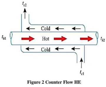
The another type of HE is Counter Flow HE, in this HE, the high temperature fluid and low temperature fluid flows in opposite direction. This type of HE are common in industries because of flow direction and effective rate of heat transfer. Figure 2 shows the counter flow HE.
Figure 2 Counter Flow HE
II. EXPERIMENTATION
A] Setup:
[image:1.612.352.532.424.572.2]International Journal of Emerging Technology and Advanced Engineering
Website: www.ijetae.com (ISSN 2250-2459, ISO 9001:2008 Certified Journal, Volume 9, Issue 9, September 2019)
30
The double pipe heat exchanger has been fabricated by using 25.4 mm diameter shell and 12.7 mm diameter tube made by Galvanized Iron. The other tubes are coated by Zinc, Copper and Brass material with thickness 1 micron. The geyser has been used here is 3 liter capacity having power consumption rate 3000 watt. Within 10 minutes, thewater starts heating up to 700C. The pump used have 0.5
[image:2.612.338.546.136.275.2]HP, 2800 RPM. The centrifugal pump is used for the experimental work having the maximum head up to 25 feet. Four Thermocouples of K type (DS18B20) are mounted to indicate the temperature of hot water inlet, hot water outlet, cold water inlet and cold water outlet. Also, two flow sensors (YS201) are used to measure the flow rates of hot as well as cold water. All sensors have been placed on respective positions of heat exchanger and Arduino UNO had used to display the readings from sensors. The PVC pipe line has been used to circulate the cold water through system and insulated hot water line has been used for hot water. The arrangement of parallel flow and counter flow was done by operating various valves. The Table 1 and 2 shows the observations for Parallel and Counter Flow HE.
[image:2.612.66.272.383.545.2]Figure 3 Experimental Setup
Figure 4 Water Flow Circuit Diagram of HE
B] Experimental Procedure
The trial of heat exchanger has been taken by changing the coated tubes and comparison made based on coated tubes and GI tube. For that event, following procedure was adopted in parallel flow as well as in counter flow:
1. Initially, make sure that all electrical connections
are proper.
2. Use first GI Tube for testing.
3. Make parallel flow arrangement.
4. Start the pump and geyser and allow water to pass
through system.
5. Check the display unit and observe the temperatures
read by thermocouples and flow rate of both fluids.
6. When the ideal conditions are reached (i.e. the hot
water temperature is 650C, and both flow rate are
0.04 Kg/s by bypass valve)
7. Note down the all observations shown by display
unit.
8. After taking the readings for parallel flow, switch
OFF the system.
9. Again make the counter flow arrangement.
10. Follow the procedure from step 4 to step 7 for
counter flow arrangement.
11. After complete observations using GI tube, change
the tube by Zinc Coated Tube using disassembly of heat exchanger.
12. Again follow the same procedure from step 1 to step
10 for observations.
13. Repeat steps for Copper tubes and Brass Tubes in
International Journal of Emerging Technology and Advanced Engineering
Website: www.ijetae.com (ISSN 2250-2459, ISO 9001:2008 Certified Journal, Volume 9, Issue 9, September 2019)
31
Table 1Observations (Parallel Flow)
Sr. No . T y p e o f T u b e Ho t Water I n let T em p . ( 0 C) Ho t Water Ou tlet T em p . ( 0 C) C o ld W ater I n let T em p . ( 0 C) C o ld W ater Ou tlet T em p . ( 0 C) Ho t Water Flo w R ate (Kg /s ) C o ld W ater Flo w R ate (Kg /s ) 1 Un co
ated 65 53 30 41 0.04 0.04
2
Z
n
C
o
ated 65 51 30 42
0.04 0.04 3 C u C o
ated 65 50 30 42
0.04 0.04 4 B r C o
ated 65 50 30 40
0.04 0.04
Table 2
Observations (Counter Flow)
Sr. No . T y p e o f T u b e Ho t Water I n let T em p . ( 0 C) Ho t Water Ou tlet T em p . ( 0 C) C o ld W ater I n let T em p . ( 0 C) C o ld W ater Ou tlet T em p . ( 0 C) Ho t Water Flo w R ate (Kg /s ) C o ld W ater Flo w R ate (Kg /s ) 1 Un co ate
d 65 54 30 40 0.04 0.04
2
Z
n
C
o
ated 65 56 30 40
0.04 0.04 3 C u C o
ated 65 54 30 46
0.04 0.04 4 B r C o
ated 65 55 30 43
International Journal of Emerging Technology and Advanced Engineering
Website: www.ijetae.com (ISSN 2250-2459, ISO 9001:2008 Certified Journal, Volume 9, Issue 9, September 2019)
32
C] Sample CalculationsFor Parallel Flow Uncoated Tube
Temperature of Hot Water Inlet (Thi) = 650C
Temperature of Hot Water Outlet (Tho) = 53
0 C
Temperature of Cold Water Inlet (Tci) = 300C
Temperature of Cold Water Outlet (Tco) = 410C
Theta1 = Thi - Tci = 65-30 = 35
Theta2 = Tho - Tco = 53-41 = 12
LMTD = 21.486
[image:4.612.65.272.421.717.2]
Similarly all the calculations are tabulated in Table 3.
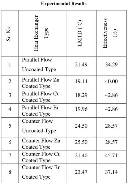
Table 3 Experimental Results
S
r.
No
.
He
at
Ex
ch
an
g
er
Ty
p
e
LM
TD
(
0 C)
Eff
ec
ti
v
en
ess
(%
)
1 Parallel Flow
Uncoated Type 21.49 34.29
2 Parallel Flow Zn
Coated Type 19.14 40.00
3 Parallel Flow Cu
Coated Type 18.29 42.86
4 Parallel Flow Br
Coated Type 19.96 42.86
5 Counter Flow
Uncoated Type 24.50 28.57
6 Counter Flow Zn
Coated Type 25.50 28.57
7 Counter Flow Cu
Coated Type 21.40 45.71
8 Counter Flow Br
Coated Type 23.47 37.14
III. COMPRESSIBLE FLUID DYNAMICS (CFD)ANALYSIS
Heat transfer analysis has been performed in ANSYS Fluent 19.0 software. Initially, a geometry had modelled in geometry modeler. The dimensions taken for designing the heat exchanger are shell diameter is 25.4 mm and tube diameter is 12.7 mm. the overall length of heat exchanger is 800 mm. A fluid domain has been added in geometry by considering volume enclosed by shell and tube. The inlets and outlets are specified and boundary conditions are specified. After that meshing has been done. The default mesh size is selected and mesh sizing is performed with face meshing to obtain accurate results. The material properties are specified. After doing all necessary conditions, the solution has started and results are shown by temperature counters (Figure 5, 6) and volume rendering (Figure 7).
A] Steps for Ansys Fluent
1. Start Ansys Fluent in Workbench.
2. Create the geometry of heat exchanger using given
details. (Shell diameter =25.4 mm, Tube diameter =12.7 mm, Length = 800 mm)
3. Create the solid domain and fluid domain.
4. Name the inlet, outlet and wall as per both fluids.
5. Go to setup
6. Mesh the generated geometry. (Use default meshing
and mesh sizing with face meshing)
7. Define the materials and fluids. (GI for Shell, select
the material for tube as required for analysis, water as fluid)
8. Specify the boundary conditions. (Hot and cold
water inlets and outlets, temperature of both fluids inlet)
9. Solve the model with default setting parameters and
up to 50 iterations.
10. Observe the results by adding temperature counters
at inlet and outlet.
11. Observe the volume rendering along length of heat
exchanger for temperature variation.
12. Perform above steps for all types of heat
International Journal of Emerging Technology and Advanced Engineering
Website: www.ijetae.com (ISSN 2250-2459, ISO 9001:2008 Certified Journal, Volume 9, Issue 9, September 2019)
[image:5.612.57.552.90.563.2]33
Figure 5 Temperature Counter for Inlet of Parallel Flow UncoatedHeat Exchanger
[image:5.612.336.550.151.564.2]Figure 6 Temperature Counter for Outlet of Parallel Flow Uncoated Heat Exchanger
Figure 7 Volume Rendering for Parallel Flow Uncoated Heat Exchanger
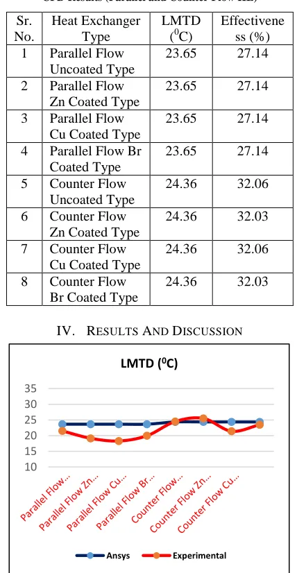
Table 4
CFD Results (Parallel and Counter Flow HE)
Sr. No.
Heat Exchanger Type
LMTD
(0C)
Effectivene ss (%)
1 Parallel Flow
Uncoated Type
23.65 27.14
2 Parallel Flow
Zn Coated Type
23.65 27.14
3 Parallel Flow
Cu Coated Type
23.65 27.14
4 Parallel Flow Br
Coated Type
23.65 27.14
5 Counter Flow
Uncoated Type
24.36 32.06
6 Counter Flow
Zn Coated Type
24.36 32.03
7 Counter Flow
Cu Coated Type
24.36 32.06
8 Counter Flow
Br Coated Type
24.36 32.03
IV. RESULTS AND DISCUSSION
Figure 8 Comparison of LMTD by Experimental and Ansys Method
10 15 20 25 30 35
LMTD (0C)
[image:5.612.72.261.423.547.2]International Journal of Emerging Technology and Advanced Engineering
Website: www.ijetae.com (ISSN 2250-2459, ISO 9001:2008 Certified Journal, Volume 9, Issue 9, September 2019)
34
Figure 8 shows the comparison between the
experimental and Ansys values of LMTD. All the values are close to the agreement. The maximum value of LMTD observed is 25.50 for counter flow with zinc coated tube experimentally to that of all counter flow arrangements by Ansys which is 24.36. This proves that the experimental setup is quite better and results within agreements. There is slight variation in LMTD by using coatings. The thickness of coating is also one of the criteria for variation in LMTD. The Ansys method gives same results for parallel and counter flow with coatings. Since the coating thickness considered here is 1 micron is too smaller to enhance the heat transfer rate.
Figure 9 Comparison of Effectiveness by Experimental and Ansys
Method
Figure 9 shows the comparison between the experimental and Ansys values of effectiveness. All the values are close to the agreement. The maximum value of effectiveness observed is 45.71 for counter flow with copper coated tube experimentally to that of all counter flow arrangements by Ansys which is 32.06.
V. CONCLUSION
The present study includes the performance of heat exchanger by using different coatings. For that purpose four materials are selected galvanized iron, zinc, copper and brass. Coating thickness of 1 micron had done on tube at outer side of heat exchanger. The experimental and Ansys Fluent method was adopted for measuring the performance of heat exchanger.
It can be concluded from the study that the heat exchanger performance depends on various parameters including hot water and cold water temperatures, mass flow rates and properties. The variation in any of the parameter results in change of performance.
It is concluded that the experimental method is well suitable for obtaining the performance of such heat exchangers. The Ansys method gives the results but it is complex and time consuming. However, experimental work can be validated with Ansys work.
It is concluded that the coating changes the performance of heat exchanger. The maximum effectiveness obtained in copper coated counter flow heat exchanger and is 45.71%. Thus it is concluded that, it is better to use copper coating for heat exchange process. Because of coating it is also concluded that the surface area of coated surface is useful in heat exchange. It is also concluded that the costing thickness of 1 micron does not change the considerable performance of heat exchanger.
REFERENCES
[1] Vincent W. Antonetti and M. Michael Yovanovich, Using Metallic Coatings to Enhance Thermal Contact Conductance of Electronic Packages, Heat Transfer Engineering, 9(3), 1988, 87-95.
[2] Shivali Jindal, Sanjeev Anand, Lloyd Metzger and Jayendra Amamcharla, A comparison of biofilm development on stainless steel and modified-surface plate heat exchangers during a 17-h milk pasteurization run, Journal of Dairy Science, 101, 2018, 2921-2926. [3] Nikolaos Vourdas, Hussam Jouhara, Savvas A. Tassou, Vassilis N.
Stathopoulos, Design criteria for coatings in next generation condensing economizers, Energy Procedia, 161, 2019, 412–420. [4] K.V. Sreenivasa Rao, Girisha K.G., Pooja Shree R., Manish Kumar,
Effect of Surface Coatings on Thermal performance of steel Substrates, Materials Today: Proceedings, 4, 2017, 10249–10253. [5] D. Josell, J. E. Bonevich, T. M. Nguyen, R. N. Johnson, Heat
transfer through nanoscale multilayered thermal barrier coatings at elevated temperatures, Surface & Coatings Technology, 275, 2015, 75–83.
[6] David J. Kukulka, Paul Leising, Evaluation of heat exchanger surface coatings, Applied Thermal Engineering, 30, 2010, 2333-2338.
[7] Yuan-Yang Li, Zhen-Hua Liu, Bao-Chen Zheng, Experimental study on the saturated pool boiling heat transfer on nano-scale modification surface, International Journal of Heat and Mass Transfer, 84, 2015, 550–561.
[8] Mahir Faris Abdullah, Rozli Zulkifli, Zambri Harun, Shahrir Abdullah, Wan Aizon Wan Ghopa, Asmaa Soheil Najm and Noor Humam Sulaiman, Impact of the TiO2 Nano solution Concentration on Heat Transfer Enhancement of the Twin Impingement Jet of a Heated Aluminum Plate, Micromachines, 10(176), 2019, 1-20. [9] R. Senthilkumar, A. J. D. Nandhakumar, S. Prabhu, Analysis of
natural convective heat transfer of nano coated aluminium fins using Taguchi method, Heat Mass Transfer, 49, 2013, 55-64.
0 10 20 30 40 50 60 70 80
Effectiveness (%)
[image:6.612.58.279.296.480.2]International Journal of Emerging Technology and Advanced Engineering
Website: www.ijetae.com (ISSN 2250-2459, ISO 9001:2008 Certified Journal, Volume 9, Issue 9, September 2019)
35
[10] S. J. Thiagarajan, W. Wang, and R. Yang, Enhancement of Heat Transfer with Pool and Spray Impingement Boiling on Microporous and Nanowire Surface Coatings, 14th International Heat Transfer Conference (IHTC-14), Washington, DC, 2010, 1-8.
[11] Thermal Performance of Coatings Used to Insulate Pipes, Ducts, and Equipment, A report by NAIMA, www.naima.org, assessed on 12-08-2019.
[12] Mr. Santosh K Katarki and Mr. Anandkumar S. Malipatil, CFD Analysis of Shell and Tube Heat Exchanger for Heat Transfer Capabilities, International Journal of Engineering and Techniques, 3(6), 2017, 102-107.
[13] Aysar A. Alamery, Zainab F. Mahdi, Hussein A. Jawad, Investigation of Metal and Metal Oxide nanocoating on Fins in HPHE with Silver Water NanoFluid, American Journal of Mechanical Engineering, 3(1), 2015, 21-25.
[14] S. Pungaiya, C. Kailasanathan, A Review of Surface Coating Technology to Increase the Heat Transfer, International Journal of Mechanical Engineering and Robotics Research, 7(5), 2018, 458-466.
[15] K. A. Rajput, A.V. Kulkarni, A Review on Effect of Perforation and Carbon Nanotubes Coating on Heat Transfer Augmentation, International Journal of Innovative Research in Science, Engineering and Technology, 3(2), 2014, 9412-9415.
[16] Sneha. H. Dhoria, E. Manoj Kumar, I. V. S. Yeswanth, Lakshmi Jayanti, CFD Analysis on Concentric Tube Heat Exchanger in Parallel and Counter Flow Direction, Journal of Engineering Research and Application, 8(6), 2018, 20-25.
[17] David J. Kukulka, Evaluation of Surface Coatings on Heat Exchangers, https://www.researchgate.net/publication/242379542, 2009, 1-7.
[18] Sujith Kumar C. S, S. Suresh, Rajiv K, Heat Transfer Enhancement by Nano Structured Carbon Nanotube Coating, International Journal of Scientific & Engineering Research, 3(6), 2012, 1-5.
[19] Manikandan. D, Thirumalvalavan. S, Analysis and Experimental Investigation of Surface Modification in EN8 Steel by Using Thermal Spray Technique, International Journal of Innovative Research in Science, Engineering and Technology, 4(6), 2015, 1697-1704.
[20] J. P. Holman, Heat Transfer, Tenth Edition, the McGraw Hill Companies, ISBN 978–0–07–352936–3, 2010, 537-550.
[21] C. P. Kothandaraman, Fundamentals of Heat and Mass Transfer, Third Edition, New Age International (P)Ltd., ISBN (13) : 978-81-224-2642-7, 2006, 520-535.