International Journal of Emerging Technology and Advanced Engineering
Website: www.ijetae.com (ISSN 2250-2459,ISO 9001:2008 Certified Journal, Volume 3, Issue 12, December 2013)
174
Determination of Total Internal Heat Transfer Coefficient of
Single Slope Solar Still with Different Depth of Water
Jyoti Raikwar
1, Mukesh Pandey
2, Anurag Gour
3Department of Energy Technology And Management, U.I.T , R.G.P.V, Bhopal, M.P, India
Abstract-- Two domestic type single slope solar stills to
inclinations 230 and 300 in accordance to the latitude of
Indore (M.P) for summer conditions. Analysis of convective heat transfer coefficient was done based on the normal
atmospheric conditions. The yield with both 230 and 300 of
inclinations and in considerations with different parameters such as depth of water , latitude of Indore and inclinations of upper surface was evaluated. After the evaluations and
calculations it was found that the yield in case of 300
inclinations. Solar still was more and increase with the increase in the angle of inclinations.
Keywords-- Heat transfer coefficient, solar distillation.
I. INTRODUCTION
The basic process for solar distillation is converting is converting salt water / saline water from sea into potable water by using solar energy. Due to the increase in demand of distill water in the feild of biomedical industries,batteries, automobiles and other industries. It
has become the need of the day to avail such huge quantity of water every day. A study on the present conditions of research work was carried out to achieve the distill water at more efficient and faster rate. Only two domestic type single slope solar stills with different angles of inclinations were designed. According to the latitude of Indore monthly performance of both the still were studied for the installations at Indore.
II. METHODOLOGY
Experimental procedure: Two domestic type single slope solar stills of 230 and 300 inclinations are designed according to the latitude of Indore. The base of both solar stills is of dimensions 50X50 cm. The entire still is covered by a FRP (fibre rainforced plastic) sheet while the upper surface of the still is covered by a toughened glass. It consist of one inlet and one outlet. Both the solar still consists of water at different depths. The evaporative pan was covered bysheet of clear glass which is tilted at different angle to let fresh water that conenses on its underside move down to a collecting trough. For different modes of experimentation and different depth . some parameters were measured every hour for a period of 24 hour.
1. Total radiation on the glass cover. 2. Diffuse radiation on the glass cover .
3. Global radiation on the glass.
4. Inner glass temperature.
5.Temperature of fresh water in the still.
6. Temperature of vapour on the glss cover .
7. Ambient temperature.
8. Output from the still.
The temperature of outer glass, inner glass, vapour were observed and noted with the help of temperature indicators. The hourly difference between solar radiation, glass cover ambient temperature and hourly yield was recorded. The hourly output with different depth of water were used to calculate the values of different heat transfer coefficients. The values of the observations are shown in the table. The present result s of these value will be used in calculating and comparing the heat transfer coefficients. The photograph of the active solar still used for experimentation are shown in the fig.
The methodology used by Tiwari & Shruti (1998), and Kumar and Tiwari 1996 evaluating c & n. We know the relation between Nusselt no. , Grashoff no., Prendtl no.
Nu=f(Gr.Pr )
For heat flow from the horizontal water surface in the upward direction, i.e. against the forces of gravity, Jakob (1994, 1957) has suggested the following relationship by correlating the experimental data of Mull and Reiher:
Nu= C (Gr.Pr)n
Nu = (hcw.d/k) = C(Gr.Pr)n
hcw = (k/d) C(Gr.Pr) n
The relation between evaporative heat transfer coefficient and convective heat transfer coefficient.
hew = 0.016273*hcw*(Pw-Pci / Tw-Tci)
hew = 0.016273*[(k/a)c(Gr.Pr) n
*(Pw-Pci/ Tw-Tci)]
Thus the heat transfer per unit area per unit time evaporation from the water surface to glass cover
qew = hew (Tw-Tci)
qew= 0.016273*[(k/d)c(Gr.Pr) n
*(Pw-Pci / Tw-Tci)*(Tw-Tci)]
= 0.016273[(k/d)c(Gr.Pr)n(Pw-Pci)]
It can also be written as qew = hew (Tw-Tci)
The rate of mass transfer mew is given by
International Journal of Emerging Technology and Advanced Engineering
Website: www.ijetae.com (ISSN 2250-2459,ISO 9001:2008 Certified Journal, Volume 3, Issue 12, December 2013)
175
mw = 0.016273(Pw-Pci)(k/d)c(Gr.Pr) n
*(3600/L)*Aw
let, R=0.016273(Pw-Pci)(k/d)(3600/L)*(0.5*0.5)
mw=RC(Ra)n
therefore, Ra= (Gr.Pr)
mw/R =C(Ra)n ……….(1)
equation (1) can be written as,
y = a xb ………(2)
where, y= mw/R ; a=c ; x=Ra ; b=
n
Equation (2) can be reduced in an equation of straight line by taking log on both sides
III. THERMAL EQUATIONS FOR ANALYSIS
Evaluation of Convective Heat Transfer Coefficient
Convective heat transfer coefficient can be defined as the amount of heat transmitted for a unit temperature difference between the fluid and unit area of the surface in unit time. The value of hc depends on the following
factors:
1. Thermodynamic and transport property
(viscosity, density, specific heat etc.) 2. Nature of fluid flow
3. Geometry of the surface
Some dimensionless number:
1. Nusselt’s no.(Nu) = hcw/(k/d) = convective heat
transfer coefficient/ conductive heat transfer coefficient
2. Grashoff’s no.( Gr) = gβd3ρ2Δt/µ2 = Buoyancy force/ Viscous force
3. Prendtl no.(Pr) =µCp/k =momentum diffusivity/
thermal diffusivity 4. Rayleigh no.(Ra) = (Gr.Pr)
In actual convection, transition in a boundary layer depends on the relative magnitude of the buoyancy and viscous force in the fluid. It is correlated in terms of a Ra number, which is the product of Gr and Pr numbers, where Gr looks after the type of flow and Pr the type of fluid. The temperature dependent physical properties of vapour (humid air) used.
Temperature dependent physical properties of vapour
Quantity SymbolExpression
Specific heat Cp 999.2+0.1434 x Tv +
1.101 x 10⁻⁴x Tv2-6.7581x 10⁻⁸x Tv3
Density ρ 353.44/(Tv x 273.15)
Thermal conductivity k 0.0244 x 0.7673 x 10-4
x Tv
Viscosity μ 10718 x 10-5 + 4.620 x
10-8xTv
Latent heat of L 3.1615x106
x[1-(7.616x10⁻⁴xTv)];
Vaporization of water
for Tv > 700C
2.4935x106x[1-9.4779x10⁻⁴Tv + 1.3132x10 -7
xTv 2
-
Partial saturated Vapor Pci exp[25.317 – 5144/(Tci
+ 273)]
pressure at condensing
cover temperature
Partial saturated vapor Pw exp[25.317 – 5144/(Tw
+ 273)]
pressure at water
temperatureExpansion factor β 1/(Tv + 273.15)
Determination of Radiative Heat Transfer Coefficient
Hrw=€effσ[(Tw+273)2+(Tg+273)2][Tw+Tg+546]
Where Hrw is the radiative heat transfer coefficient
from the water surface to the glass cover
Determination of Evaporative Heat Transfer Coefficient
Hew = 16.273*10-3Hcw(Pw-Pg)/(Tw-Tg)
IV. OBSERVATIONS
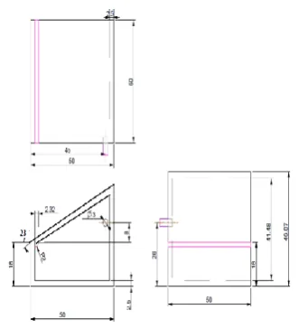
[image:2.595.350.516.538.720.2]Dimension of single slope solar still with 23o inclination
International Journal of Emerging Technology and Advanced Engineering
Website: www.ijetae.com (ISSN 2250-2459,ISO 9001:2008 Certified Journal, Volume 3, Issue 12, December 2013)
[image:3.595.90.246.157.383.2]176
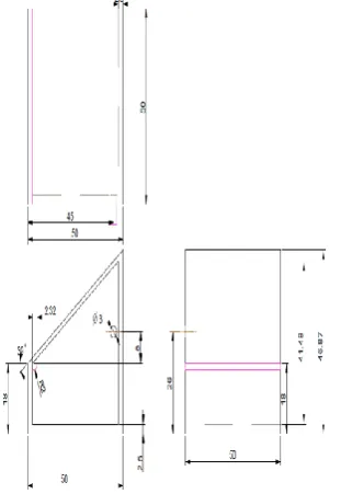
Dimensions of single slope solar still with 30o inclinationFig : layout of single slope solar still with 30o inclination
S No
. Time Ig
(W/m2
) Id
(W/m2
) Tw
(o
C) Tgi
(o
C) Tgo
(o
C) Ta
(o
C) Ya
(%) Yield
(ml)
1 7:00 83.33 55.9 24 26 25 25 30.7 0
2 8:00 270 86.8 26 32 30 27 40 1
3 9:00 570 100 29 39 36 21 31 1
4 10:00 805 110 34 41 38 31 25 1
5 11:00 929 101 39 43 41 32 17 2.3
6 12:00 1005 120 46 47 45 33 19 32.3 7 13:00 950 122 50 46 42 33 12 58.1
8 14:00 863 113 50 47 44 34 10 62.2
9 15:00 611 83 49 45 40 33 13 76.8
10 16:00 320 65 47 43 39 34 10 66
11 17:00 77 44 43 38 34 33 10 40.5
12 18:00 29 25 39 34 31 31 10 47.2
13 19:00 0 0 36 31 29 30 10 25.4
14 20:00 0 0 33 29 27 28 10 23.2
15 21:00 0 0 31 27 26 27 10 15.4
16 22:00 0 0 29 26 25 26 11 12.3 17 23:00 0 0 28 25 24 26 12 8.3
18 0:00 0 0 27 24 24 26 11 8.3
19 1:00 0 0 26 24 24 25 18 6.2
20 2:00 0 0 26 24 23 25 20 5
21 3:00 0 0 25 24 23 26 25 4
22 4:00 0 0 25 23 22 24 24 5
23 5:00 0 0 25 23 22 22 27 4
International Journal of Emerging Technology and Advanced Engineering
Website: www.ijetae.com (ISSN 2250-2459,ISO 9001:2008 Certified Journal, Volume 3, Issue 12, December 2013)
177
Gr Pr C N
hc, TI
hc, DUNK
Overall η
8583629 0.69831 1.176666 0.175336 1.747766 2.99388
20.80294
14788817 0.697564 1.914303 2.743343
13279513 0.696889 1.901196 2.546813
7249922 0.696354 1.727299 2.163041
2479885 0.695692 1.450156 2.093199
5121964 0.695198 1.661585 3.165901
12046952 0.69506 1.934306 3.299629
12012294 0.695129 1.930727 3.527615
13613146 0.695373 1.964028 3.377735
15133019 0.695837 1.983015 2.759136
16688706 0.696467 1.993725 2.947699
16694917 0.697006 1.974546 2.197827
15089053 0.697443 1.925094 2.087932
13495551 0.697809 1.87600 1.551013
11884593 0.698099 1.825742 0.96726
10241822 0.69831 1.772618 1.36539
10293312 0.69848 1.769103 1.228968
8610613 0.698609 1.711153 2.010291
6896720 0.698652 1.644952 2.177648
5178926 0.698696 1.56361 2.435995
5194216 0.698782 1.562166 2.356106
6937436 0.698826 1.641913 2.510954
International Journal of Emerging Technology and Advanced Engineering
Website: www.ijetae.com (ISSN 2250-2459,ISO 9001:2008 Certified Journal, Volume 3, Issue 12, December 2013)
178
S
No. Time
Ig
(W/m2)
Id
(W/m2)
Tw
(oC) Tgi
(oC) Tgo
(oC) Ta
(oC) Ya
(%) Yield
(ml)
1 7:00 100 32 25 27 25 25 31 0
2 8:00 300 75 25 32 31 27 37 6.9
3 9:00 590 86 27 37 36 30 38 6
4 10:00 831 96 30 41 41 31 18 0.5
5 11:00 941 108 34 44 42 32 16 1
6 12:00 982 110 40 45 45 33 12 8
7 13:00 918 130 44 47 44 33 23 16.3
8 14:00 781 95 47 47 45 34 17 33.2
9 15:00 540 78 47 46 43 33 10 45.2
10 16:00 310 65 46 42 38 34 10 43
11 17:00 80 50 44 39 36 33 10 46.2
12 18:00 26 25 42 36 32 32 15 53
13 19:00 0 0 40 33 30 30 13 25.1
14 20:00 0 0 37 31 28 29 11 33.2
15 21:00 0 0 35 29 27 28 10 27.3
16 22:00 0 0 33 29 27 28 10 23
17 23:00 0 0 32 27 26 27 11 20
18 0:00 0 0 31 27 26 27 15 15.2
19 1:00 0 0 30 26 25 26 16 13.1
20 2:00 0 0 29 26 25 27 15 8.8
21 3:00 0 0 28 26 24 26 17 6.2
22 4:00 0 0 28 25 23 25 19 8.1
23 5:00 0 0 27 24 23 25 18 4.2
24 6:00 5 4 26 23 22 24 18 8.1
Gr Pr C N
hc, TI
hc, DUNK
Ove rall η
8583629 0.69831 1.176666 0.175336 1.747766 2.99388 20.8 0294
14788817 0.697564 1.914303 2.743343
13279513 0.696889 1.901196 2.546813
7249922 0.696354 1.727299 2.163041
2479885 0.695692 1.450156 2.093199
5121964 0.695198 1.661585 3.165901
12046952 0.69506 1.934306 3.299629
12012294 0.695129 1.930727 3.527615
13613146 0.695373 1.964028 3.377735
15133019 0.695837 1.983015 2.759136
16688706 0.696467 1.993725 2.947699
16694917 0.697006 1.974546 2.197827
15089053 0.697443 1.925094 2.087932
13495551 0.697809 1.87600 1.551013
11884593 0.698099 1.825742 0.96726
10241822 0.69831 1.772618 1.36539
10293312 0.69848 1.769103 1.228968
8610613 0.698609 1.711153 2.010291
6896720 0.698652 1.644952 2.177648
5178926 0.698696 1.56361 2.435995
5194216 0.698782 1.562166 2.356106
6937436 0.698826 1.641913 2.510954
International Journal of Emerging Technology and Advanced Engineering
Website: www.ijetae.com (ISSN 2250-2459,ISO 9001:2008 Certified Journal, Volume 3, Issue 12, December 2013)
179
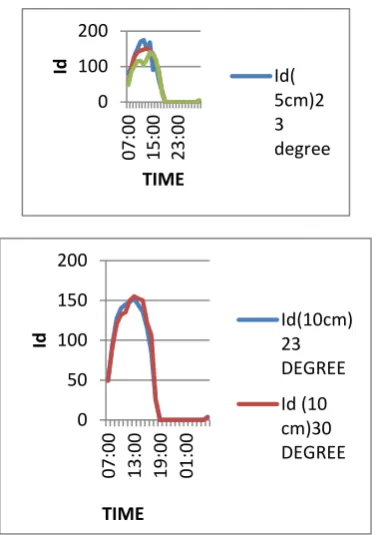
IV. COMPARISION OF IDFOR BOTH STILL
The diffused radiation for both still at different water level as illustrated below and it is found that the higher value is found in case of 15cm depth of water for both still at different angle of inclination.
0 100 200
07
:0
0
15
:0
0
23
:0
0
Id
TIME
Id( 5cm)2 3 degree
0 50 100 150 200
07
:0
0
13
:0
0
19
:0
0
01
:0
0
Id
TIME
[image:6.595.71.260.198.466.2]Id(10cm) 23 DEGREE Id (10 cm)30 DEGREE
TABLE FOR CONVECTIVE HEAT TRANSFER COEFFICIENT
30 DEGREE INCLINATION
TIME
23 DEGREE INCLINATION
DEPTH OF WATER DEPTH OF
WATER
S.NO 5CM 5CM 5CM 10CM
1
1.537856 1.318744 7.00 1.92654 1.726989
2
1.749102 1.59596 8.00 2.099574 1.945465
3
1.786233 1.727546 9.00 2.065263 2.001262
4
1.739187 1.75516 10.00 1.869692 1.994681
5
1.571702 1.691017 11.00 1.326273 1.906658
6
1.2374 1.536142 12.00 2.06658 1.610058
7
1.545311 1.373269 13.00 1.988567 1.944754
8
1.870337 1.389794 14.00 2.205859 2.058639
9
1.956737 1.76753 15.00 2.356148 2.117417
10
1.963574 1.854881 16.00 2.293174 2.101508
11
1.992532 1.879231 17.00 2.31198 2.086163
12
1.971891 1.881194 18.00 2.253482 1.627253
13
1.93289 1.867868 19.00 2.236043 1.632359
14
1.89838 1.860228 21.00 2.185946 2.046008
15
1.862505 1.836977 22.00 2.085021 2.020404
16
1.826971 1.812842 23.00 2.02306 2.015128
17
1.713019 1.787634 00.00 1.950567 2.009923
18
1.605438 1.761111 01.00 1.86192 2.004788
19
1.658996 1.756892 02.00 1.85993 1.99972
20
1.657215 1.752769 03.00 1.745035 1.994718
21
1.655459 1.748739 04.00 1.743212 1.970188
22
1.700077 1.746757 05.00 1.854142 1.967761
23
International Journal of Emerging Technology and Advanced Engineering
Website: www.ijetae.com (ISSN 2250-2459,ISO 9001:2008 Certified Journal, Volume 3, Issue 12, December 2013)
180
V. COMPARISION OF IgFOR BOTH STILL
The global radiation for both the still varies with almost same characteristics and it is found higher during time interval 11am to 2 pm in this interval the global radiation is almost 1000 to 1050W/m2.
And the comparison of the Ig for same depth of water
separately for both still is also illustrated in fig as this varies almost similar way there is no more deviation found.
VI.COMPARISION OF TwFOR BOTH STILL
The variation of temprature of water for both still at different water level is illustrated and is found its value higher when the depth of water is minimum and its value is approximately 54 degree in all cases either seperately at different level or combined for both the still. And its value is higher during time 1to 2 pm and water temprature varies similarly for different depth at difffrent angle of onclination.
VII. COMPARISION OF TgiFOR BOTH STILL
The variation of temprature of inner glass surface with different glass cover inclination at difrent depth of water is illustrated its variation is similar for both still and higher value is also same for all depth of watereither seperately or combined and its value is approximately equal to52 degree centigrate and it is found during 1pm to 2pm.
VIII.COMPARISION OF TgoFOR BOTH STILL
The variation of temprature of outer glass surface with different glass cover inclination at difrent depth of water is illustrated its variation is similar for both still and higher value is also same for all depth of watereither seperately or combined and its value is approximately equal to51 degree centigrate and it is found during 1pm to 2pm 0 500 1000 1500 07 :0 0 12 :0 0 17 :0 0 22 :0 0 03 :0 0 Ig TIME Ig(5 cm)30 DEGREE Ig(5 cm)23 DEGREE 0 500 1000 1500 07 :0 0 12 :0 0 17 :0 0 22 :0 0 03 :0 0 Ig TIME Ig(10 cm)30 DEGREE Ig(10 cm)23 DEGREE 0 20 40 60 07 :0 0 12 :0 0 17 :0 0 22 :0 0 03 :0 0 Tw TIME Tw10 CM 30 DEGREE Tw(10 CM) 23 DEGREE 0 20 40 60 7: 00 12 :0 0 17 :0 0 22 :0 0 3: 00 Tgi TIME Tgi(10 CM 30 DEGREE) 0 50 100 7: 00 12 :0 0 17 :0 0 22
:00 3:00
International Journal of Emerging Technology and Advanced Engineering
Website: www.ijetae.com (ISSN 2250-2459,ISO 9001:2008 Certified Journal, Volume 3, Issue 12, December 2013)
181
IX. COMPARISION OF YEILD FOR BOTH STILL
The variation of yield with different angle of inclination of different depth of water is illustrated bellow . the value of yeild is found higher at 5cm depth of water for both the still during 3pm to 4pm but when the grapf is ploted seperately at same depth of water and different angle of inlination is also shown.the higher value is found in 30 degree angle of inclination for all the depth of water seperately and it is found during same time intervalas above for combined graph.
X. RESULT AND DISCUSSION
The fig indicates that the internal heat transfer coefficient decreases with the increase of water pepth in the basin due to decrease in the temperature difference between glass and water temperature . Further it is impotannt to note that the fluctuations in internal convective heat transfer coefficient decrease with the increase of water depth due to storage effect presents the theoretical and experimental results of the hourly yield for the studied water depths in the basin. From table it is observed that there is a fair agreement between the fluctuations in internal convective heat transfer coefficient decrease with the increase of water depth due to storage effect presents the theoretical and experimental results of the hourly yield for the studied water depths in the basin.
From table it is observed that there is a fair agreement between the experimental and theoretical results. For 0.05 meter depth in the basin. However for higher depths (0.10m and 0.15m), the fluctuations between the experimental and theoretical results is large. Convective heat transfer coefficients is found higher for 10cm depth of water except 12 :00 noon to 3:00 pm during this period convective heat transfer is higher for 0.5 cm depth of water. This is due to higher solar energy available for less quantity of water . Hence it is depicted that 10 cm depth of water is favourable to achieve higher convective heat transfer coefficient.
After experiment and calculation we conclude that 30 degree inclination of still is more efficient and effective for all point of view as heat transfer coefficient, yield, global radiation, defused radiation etc because in this case its value is found higher than 23 degree inclination of angle.
We all conclude that at the angle of inclination is found optimum hence it is equal to the altitude of the place where it is setup and experimentation is done.After experiment and calculation we conclude that 30 degree inclination of still is more efficient and effective for all point of view as heat transfer coefficient, yield, global radiation, defused radiation etc because in this case its value is found higher than 23 degree inclination of angle.We all conclude that at the angle of inclination is found optimum hence it is equal to the altitude of the place where it is setup and experime
REFERENCES
[1] Adhikari, R.S., Kumar, A. and Sodha, G.D. (1995). Simulation studies on a multi-stage stacked tray solar still, J. Solar Energy.
54(5), 317.
[2] Aggarwal, S. and Tiwari, G.N. (1998). Convective mass transfer in a double-condensing chamber and a conventional solar still. J. Desalination. 115 (2), 181.
[3] Ahmed, S.T. (1988). Study of single effect solar still with an internal condenser. Int. J. Solar and Wind Tech. 5 (6), 637. [4] Akinsete, V.A. and Duru, C.U. (1979). A cheap method of
improving the performance of roof type solar still. J. Solar Energy. 23 (3), 271.
[5] Bapeshwar, V. and Tiwari, G.N. (1984). Effect of water flow over the glass on the performance of a solar still coupled with a flat plate collector. Int. J. of Solar Energy. 2, 277.
[6] Barrera, E.C. (1993). Double effect spherical solar still. J. Sun World. 17 (1).
[7] Bassam, A., Hijleh, K.A. and Mousa, H.A. (1997). Water film cooling over the glass cover of a solar still including evaporation effects. J. Energy. 22, 43.
[8] Tiwari, G.N. (1984). Demonstration plant of multi-wick Solar still. J. Energy Conversion and Management. 24, 313.
[9] Tiwari, G.N. (1992). Recent Advances in Solar Distillation. Chapter II,
0 20 40 60
7:
00
12
:0
0
17
:0
0
22
:0
0
3:
00
Tg
o
TIME
Tgo
Tgo( 5 CM DEGREE)
0 50 100 150
7:
00
12
:0
0
17
:0
0
22
:0
0
3:
00
YI
ELD
TIME