i
Collaborative System and Multi Robots
Based on Pneumatic Muscle Actuator
Alaa Falah Abdulhasan Al-Ibadi
Autonomous Systems and Robotics Centre
School of Computing, Science & Engineering
University of Salford, Manchester, UK
ii
Contents
Contents
Contents ... ii
List of figures ... vii
List of tables ... xiv
List of Abbreviations ... xvi
List of symbols ... xvii
Dedication ... xxi
Acknowledgements ... xxii
Abstract ... xxiii
Chapter one: ... 1
1. General introduction ... 1
1.1 Main overview... 1
1.2 Aim and objectives ... 2
1.3 Research Methodology ... 2
1.4 Research contributions ... 3
1.5 List of publications ... 5
1.6 Thesis organisation ... 6
Chapter Two: ... 8
2. Types of actuators used in robotics ... 8
2.1 Introduction ... 8
2.2 Rigid actuators... 8
2.3 Actuator effect on robot-human interaction ... 8
2.3.1 Safety ... 9
iii
2.3.3 Distributed micro-mini actuator ... 12
2.3.4 Variable stiffness actuator (VSA-I) ... 13
2.3.5 Variable stiffness actuator (VSA-II) ... 13
2.3.6 CompAct-VSA ... 14
2.3.7 VSA-CubeBots ... 15
2.3.8 Robustness of variable stiffness actuators ... 16
2.4 Pneumatic muscle actuator ... 17
2.4.1 Structure of pneumatic muscle actuator ... 18
2.4.2 Operation of PMA ... 19
2.4.3 Modelling of the PMA ... 22
2.4.4 Soft robot continuum arms ... 28
2.5 Summary ... 32
Chapter Three: ... 33
3. Collaborative Robot System ... 33
3.1 Introduction ... 33
3.2 Task requirements ... 33
3.2.1 Tasks that required multiple robot arms ... 33
3.2.2 Tasks that need multiple robots ... 34
3.2.3 Task sharing ... 34
3.3 Robot-Human interaction ... 34
3.3.1 Application of Human-Robot Collaboration ... 35
3.3.2 Distribution of tasks between humans and robots ... 37
3.3.3 Industrial robots ... 37
3.4 Multi-arms robot system ... 37
3.5 Levels of collaboration ... 38
3.5.1 Low level ... 38
iv
3.5.3 High level ... 39
3.6 Communication in collaboration environment ... 39
3.7 Summary ... 39
Chapter Four: ... 40
4. Modelling of pneumatic muscle actuator ... 40
4.1 Introduction ... 40
4.2 Contractor pneumatic muscle actuator ... 40
4.2.1 Construction ... 40
4.2.2 Practical experiments ... 42
4.2.3 Structure-based models for the contractor muscle actuator ... 59
4.3 Extensor pneumatic muscle actuator ... 73
4.3.1 Construction ... 73
4.3.2 Practical experiments ... 73
4.3.3 Kinematics of the extensor continuum arm ... 86
Chapter Five: ... 88
5. Controlling of pneumatic muscle actuator ... 88
5.1 Introduction ... 88
5.2 Nonlinear PID controller ... 88
5.3 Other controller approaches ... 90
5.4 Static and dynamic controllers ... 91
5.4.1 Static control system ... 91
5.4.2 Dynamic control system ... 92
5.5 Neural Network-Proportional parallel controller ... 93
5.5.1 Length control of single extensor PMA ... 96
Chapter Six: ... 99
6. Novel structures of pneumatic muscle actuator ... 99
v
6.2 Self-bending contraction actuator (SBCA) ... 99
6.2.1 The design of the SBCA ... 100
6.2.2 Kinematics of the SBCA ... 103
6.2.3 The bending force of the SBCA ... 107
6.2.4 Experiments and validation ... 108
6.3 Double bend pneumatic muscle actuator (DB-PMA) ... 109
6.3.1 Snake motion ... 110
6.3.2 Structure of the Double-Bend Actuator ... 110
6.3.3 Kinematics of the DB-PMA ... 112
6.3.4 Experiments and Validations ... 115
6.4 Circular pneumatic muscle actuator CPMA... 117
6.4.1 Human facial muscles ... 118
6.4.2 The design of the CPMA ... 119
6.4.3 The kinematics of the CPMA ... 120
6.4.4 The radial force of the CPMA ... 122
6.4.5 Experiments and validations ... 125
Chapter Seven: ... 132
7. Active soft end effectors for efficient grasping and safe handling ... 132
7.1 Introduction ... 132
7.2 Three fingers gripper base on SBCA ... 134
7.2.1 Increment of grasping points ... 140
7.2.2 The grasping control of different loads ... 140
7.3 Extension-circular gripper ... 144
7.3.1 Three CPMAs gripper ... 147
7.3.2 The control system of the CPMAS gripper ... 149
7.4 Summary ... 150
vi
8. Novel Design and Position Control Strategy of a Soft Robot Arm ... 152
8.1 Introduction ... 152
8.2 Design and Construction of the Soft Arm ... 152
8.2.1 The Bending and Displacement Test of the Soft Arm ... 154
8.3 The Modified Design of the Proposed Arm ... 156
8.4 Controlling the Presented Soft Arm ... 158
8.4.1 Cascaded Position Control ... 158
8.4.2 Closed-Loop Position Control of the Two-Segments Soft Arm ... 167
8.5 Summary ... 173
Chapter Nine: ... 175
9. Multiple Robot System ... 175
9.1 Introduction ... 175
9.2 Robot-Robot (R-R) Collaborative System ... 175
9.2.1 Single bending continuum arms ... 175
9.2.2 Multiple bend continuum arms ... 177
9.3 Human-Robot (H-R) Interaction (HRI)... 185
9.3.1 Sharing control of HRI ... 185
9.3.2 Continuum arm by DB-PMA ... 187
Chapter Ten: ... 193
10. Summary and Future Work ... 193
10.1 Summary ... 193
10.2 Future work ... 195
References ... 196
vii
List of figures
Figure 2.1 A single rigid joint. (A. Bicchi & Tonietti, 2004). ... 10
Figure 2.2 A basic diagram of series elastic actuator. ... 11
Figure 2.3 Location of low and high frequency actuators (Zinn, Roth, Khatib, & Salisbury, 2004). ... 12
Figure 2.4 Variable stiffness actuator prototype (Bicchi, Tonietti, Bavaro, & Piccigallo, 2005). ... 13
Figure 2.5 Variable stiffness actuator VSA-II ... 14
Figure 2.6 CompAct VSA (N. G. Tsagarakis, Sardellitti, & Caldwell, 2011) ... 15
Figure 2.7 A VSA-CubeBots photograph (Catalano et al., 2011). ... 16
Figure 2.8 Variable stiffness actuator. ... 17
Figure 2.9 The structure of the pneumatic muscle actuator. ... 19
Figure 2.10 The parameters of the PMA. ... 20
Figure 2.11 Constant load test of the PMA. ... 20
Figure 2.12 Constant pressure test of the PMA ... 21
Figure 2.13 Extension PMA. (a) Before pressurizing, (b) After pressurizing. ... 22
Figure 2.14 Parameters of contraction PMA. (a) Initial values, (b) under pressure values. ... 24
Figure 2.15 Actual geometrical model of PMA. ... 26
Figure 2.16 Length definition of the PMA under certain force. ... 27
Figure 2.17 Multiple directional continuum arm with suction cup (Neppalli et al., 2007). ... 28
Figure 2.18 Two-section Air-Octor (McMahan, Jones, & Walker, 2005). ... 29
Figure 2.19 OctArm V- continuum manipulator (McMahan et al., 2006a). ... 30
Figure 2.20 Cable actuated of single extensor continuum arm (Neppalli & Jones, 2007). ... 30
Figure 2.21 Octopus inspired underwater continuum manipulator (Zheng, Branson, et al., 2012). ... 31
Figure 2.22 Variable stiffness, bending continuum robot arm (Giannaccini et al., 2018). ... 31
Figure 3.1 Possible taxonomies of robot-human interaction (Yanco & Drury, 2004) ... 35
viii
Figure 3.3 Two robots holding an object. ... 38
Figure 4.1 Parts and construction of the pneumatic muscle actuator. ... 42
Figure 4.2 Plots of actuator length change against air pressure. ... 44
Figure 4.3 The experimental data of the contractor PMAs ... 45
Figure 4.4 The validation results of the model for the three actuators ... 46
Figure 4.5 The validation results of the 25 cm PMA ... 47
Figure 4.6 The length of the actuators against the pressure at fixed weight values. ... 49
Figure 4.7 The length of the actuators against the weight at fixed pressure values ... 50
Figure 4.8 The experimental and theoretical force for the 30 cm PMA from (2.24). .... 52
Figure 4.9 The experimental and presented theoretical force for the 30 cm PMA from (4.5). ... 52
Figure 4.10 A photograph of 2-sections 60 cm PMA. ... 53
Figure 4.11 The experimental force for single 60 cm and 2-section 60 cm PMAs. ... 53
Figure 4.12 Four 30 cm PMAs laying in parallel. ... 54
Figure 4.13 Solidworks design of the arm two ends. ... 54
Figure 4.14 Length – pressure characteristic of single PMA and 4-PMAs in parallel. .. 55
Figure 4.15 Force – pressure characteristic of single PMA and 4-PMAs in parallel ... 55
Figure 4.16 Pressurized arm at certain pressure with δ degree angle. ... 56
Figure 4.17 Experimental arm angle at multi load values. ... 58
Figure 4.18 Experimental and theoretical angle values. ... 59
Figure 4.19 The cross section of the PMA structure. ... 61
Figure 4.20 The resistance force of the rubber tube against air pressure. ... 62
Figure 4.21 The contact less losses between the rubber tube and the braided sleeve against air pressure ... 63
Figure 4.22 The experimental and theoretical force of the PMA against air pressure. .. 63
Figure 4.23 The resistance force of the high stiffness rubber tube against air pressure. 64 Figure 4.24 The resistance force of the third actuator against air pressure. ... 66
Figure 4.25 The experimental and theoretical length of the PMAs are listed in table 4.14. ... 69
Figure 4.26 the length of the actuator B with contraction and elongation curve. ... 69
Figure 4.27 The experimental and theoretical stiffness of the three different PMAs. .... 72
Figure 4.28 Plots of actuator length change against air pressure. ... 75
ix Figure 4.30 The experimental and the presented theoretical force for the 30 cm extensor
PMA. ... 77
Figure 4.31 The length of the actuators against the pressure at fixed weight values. .... 79
Figure 4.32 The length of the actuators against the weight at fixed pressure values. .... 80
Figure 4.33 A 30 cm extensor PMA (a) one side sewed actuator (b) bending under 300 kPa air pressure. ... 81
Figure 4.34 Four 30 cm extensor PMAs continuum arm. ... 82
Figure 4.35 An extensor continuum arm at certain pressure. ... 83
Figure 4.36 The bending angle against the pressure at different load conditions. ... 84
Figure 4.37 The validation results for the bending angle at three different load conditions. ... 85
Figure 4.38 The geometrical analysis of the extensor continuum arm. ... 86
Figure 5.1 Two joints arm for rehabilitation process based on PMAs Thanh and Ahn (2006) ... 89
Figure 5.2 PID-ANN control structure (Thanh & Ahn, 2006) ... 89
Figure 5.3 Block diagram of Fuzzy logic control system ... 91
Figure 5.4 A block diagram of a model-based static controller system. ... 91
Figure 5.8 The schematics of the suggested controller ... 93
Figure 5.9 The relation between air pressure and duty cycle ... 96
Figure 5.10 The extensor PMA at different attached load and the position of the ultrasound sensor ... 97
Figure 5.11 The step response of the 30 cm extensor actuator at 0.5 Hz. ... 97
Figure 5.12 The step input and the model length of the 30 cm extensor actuator. ... 98
Figure 6.1 The structure of the self-bending contraction actuator version (1). ... 100
Figure 6.2 The novel structure of the SBCA version (2). (a) The structure of the SBCA showing the inserted rod. (b) The 30 cm SBCA at 300 kPa. ... 101
Figure 6.3 the experiment components ... 102
Figure 6.4 The bending angle at different attached load. ... 103
Figure 6.5 Line to circle conversion ... 104
Figure 6.6 The geometrical analysis of the SBCA ... 105
Figure 6.7 The lateral undulation locomotion of a snake. ... 110
Figure 6.8 The structure of the contraction pneumatic muscle actuator (PMA). ... 111
x
Figure 6.11 The presented DB-PMA at two different air pressures. ... 115
Figure 6.12 The parameters of the DB-PMA as a function of air pressure: (a) βm and the calculated βc angle, (b) αm and the calculated αc angle, (c) γm and the calculated γc angle, (d) λm and the calculated λcdistance between the two ends, (e) Lhm and the calculated Lhc horizontal distance, and (f) Lvm and the calculated Lvc vertical distance. ... 116
Figure 6.13 The human facial muscles including the circular muscles around the mouth and the eyes (Pinterest, 2019, June 14). ... 119
Figure 6.14 The geometrical structure of the CPMA. (a) the geometrical of the PMA. (b) The contraction actuator. (c) The circular actuator. ... 120
Figure 6.15 The geometrical structure of the CPMA as a cylinder. ... 124
Figure 6.16 The variation of the CPMA’s parameters according to the applied air pressure. (a) The outer circumference. (b) The diameter of CPMA. And (c) is the braided angle. ... 127
Figure 6.17 The validation of the CPMA’s parameters. (a) The measured and the calculated inner diameter. (b) The measured and the calculated inner circumference. ... 128
Figure 6.18 The experiment’s equipment for actuation force. ... 129
Figure 6.19 The measurement and the calculation force in kg. (a) The force according to (6.77). (b) The force according to (6.79). ... 130
Figure 7.1 A three fingers gripper based on self-bending contraction actuator ... 135
Figure 7.2 The fingertips of the gripper at different positions. ... 136
Figure 7.3 The bending angle –pressure characteristics for each finger. ... 136
Figure 7.4 The force of a single finger at different positions. ... 137
Figure 7.5 The payload–pressure characteristics for the three-fingers gripper. ... 138
Figure 7.6 Multiple objects grasped by the proposed gripper. (a) 500 g Cola can. (b) A measuring tape. (c) Pen. (d) 2.5 cm (diameter) cylinder object. (e) 5x7 cm business card. (f) A screwdriver ... 139
Figure 7.7 The layout of the six bending fingers. ... 140
Figure 7.8 The full block diagram of the grasping force control system. ... 141
Figure 7.9 The controller response for the three finger gripper. (a) The sinusoidal response at 0.25 Hz, (b) The sinusoidal response at 0.5 Hz, (c) The step response at 0.25 Hz and (d) The step response at 0.5 Hz. ... 142
Figure 7.10 The grasping force control. (a) The weight scale and the object. (b) The response of the gripper due to different load values. ... 143
xi Figure 7.12 Variation of the length and the diameter for the extension-circular gripper
... 146
Figure 7.13 The payload –pressure characteristics for the extension-circular gripper. 146 Figure 7.14 Multiple objects grasped by the extension-circular gripper. (a) 7x12 cm calculator. (b) 1.0 kg weight. (c) 6 cm (diameter) cylinder object. (d) 5x7 cm business card. (e) A measurement tape. (f) 4.0 kg rectangular object ... 147
Figure 7.15 The dimensions and the structure of the three CPMAs gripper. ... 148
Figure 7.16 Variation of the length and the diameter for the three CPMs gripper. ... 148
Figure 7.17 The grasping force control. (a) The grasping control results for the one CPMA gripper at three different loads (b) The grasping control results for the three CPMAs gripper at three different loads. ... 149
Figure 7.18 The grasping examples for the three CPMAs gripper at three different loads ... 150
Figure 8.1 The proposed soft arm. (a) The layout of actuator distributions. (b) The structure of the entire arm. ... 154
Figure 8.2 Possible direction movements by pressurising one or two actuators in each section. ... 155
Figure 8.3 The bending angle of the proposed soft arm due to three different pressurise patterns. ... 155
Figure 8.4 The modified version of the proposed soft arm. (a) The arm at no pressure. (b) and (c) represent two different bending possibilities... 157
Figure 8.5 The bending angle of the modified soft arm due to three different pressurised patterns. ... 157
Figure 8.6 The layout of the robot arm and the camera system. ... 159
Figure 8.7 Mapping of the movement data. (a) X-Y mapping. (b) X-Z mapping. (c) Y-Z mapping. ... 160
Figure 8.8 The flowchart of single pair of neural network controllers. ... 161
Figure 8.9 The full block diagram of the cascaded position control system. ... 162
Figure 8.10 A random pattern to validate the cascaded position control system. ... 163
Figure 8.11 The output and feedback air pressure for the nine actuators, which have been programmed to control the position of the multi-function soft arm at no-load by using the cascaded control system. ... 164
Figure 8.12 The desired feedback position for the multi-function soft arm by the
xii Figure 8.13 The error of x, y, z displacements, respectively (a) The x position error. (b)
The y position error and (c) is the z position error. ... 166
Figure 8.14 Joints and motion of the extension section. ... 168
Figure 8.15 The top view of the three joint movements of actuators 1, 2 and 4 at x-y plan. ... 169
Figure 8.16 The full block diagram of the closed loop position control system. ... 170
Figure 8.17 The reference and the feedback positions at 300 g. (a) Is the X and Xf position. (b) Is the Y and Yf position. And (c) Is the Z and Zf position. ... 172
Figure 8.18 The RMSE for the position control at three different load conditions. ... 172
Figure 9.1 A 30 cm bending continuum arm and the three fingers gripper ... 175
Figure 9.2 The proposed continuum arms at 90 degree. ... 176
Figure 9.3 The proposed unidirectional continuum arm and the end effector. ... 178
Figure 9.4 The bidirectional continuum arm and the soft gripper. ... 179
Figure 9.5 The bending direction of the bidirectional continuum arm. ... 179
Figure 9.6 The bidirectional continuum arm at different right-shift bending examples. ... 180
Figure 9.7 The bidirectional continuum arm at different left-shift bending examples. 181 Figure 9.8 90° bending angle of the both arms ... 181
Figure 9.9 The layout of the continuum arms and moving process of an object from position A to position C. (a) the object at position A. (b) activating arm1 and arm2. (c) ) activating arm2 and arm3. and (d) the object at position C. ... 183
Figure 9.10 Colour classification task ... 184
Figure 9.11 The wearable sensors to control the bending angle and grasping force .... 185
Figure 9.12 The bending angle for both the human hand and the continuum arm at 0.3 and 1 kg. ... 186
Figure 9.13 the human and the continuum arms at certain bending angle and grasp force ... 187
Figure 9.14 The two-fingers soft gripper based on self-bending contraction actuators (SBCA). (a) The soft gripper at different air pressures. (b) The schematic design of the soft finger. ... 188
Figure 9.15 The proposed continuum arm at different pressurised conditions. ... 188
Figure 9.16 The flowchart of the control system and the continuum arm. ... 189
xiii Figure 9.18 The horizontal moving arm of two SBCAs at different pressurising
xiv
List of tables
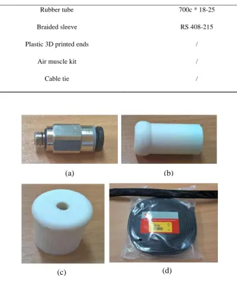
Table 4.1 Description of material used in the PMA contraction ... 41
Table 4.2 Specifications of the contractor PMAs under study ... 42
Table 4.3 maximum angle with different loads. ... 57
Table 4.4 The initial specifications of a 20 cm contraction PMA. ... 62
Table 4.5 The initial specifications of a high stiffness, 20 cm contraction PMA. ... 64
Table 4.6 The initial specifications of the new contraction PMA. ... 65
Table 4.7 The MSE of the three actuators. ... 65
Table 4.8 The specifications of the contraction PMAs. ... 67
Table 4.9 The contraction ratio of the PMAs. ... 70
Table 4.10 The MSE of the 20 cm contraction ratio PMA at different load values. ... 70
Table 4.11 Specification of the extensor PMAs under study. ... 73
Table 4.12 the maximum bending angle with different loads. ... 83
Table 6.1 The maximum bending angle at different loads ... 102
Table 6.2 The dimensions of the bending PMA ... 103
Table 6.3 The bending angle and the bending force for the SBCA. ... 109
Table 7.1 The maximum bending angle at different loads. ... 138
Table 8.1 The maximum pressure in kPa in the activated actuators at different load values. ... 173
Table 9.1 The specifications of the continuum arm. ... 177
Table 9.2 The specifications of the bending finger. ... 177
Table 9.3 The maximum bending angle for the three different self-bending contraction actuators (SBCAs) at 500 kPa. ... 191
Table A.1 Experiment results of a 20 cm PMA. ... 210
Table A.2 Experiment results of a 30 cm PMA. ... 210
Table A.3 Experiment results of a 40 cm PMA. ... 211
Table A.4 Length of a 20 cm contractor PMA due to the change in weight and pressure. ... 211
Table A.5 Length of a 30 cm contractor PMA due to the change in weight and pressure. ... 211
Table A.6 Length of a 40 cm contractor PMA due to the change in weight and pressure. ... 211
xv Table A.8 Experiment results of a 32 cm PMA. ... 211 Table A.9 Experiment results of a 42 cm PMA. ... 211 Table A.10 Length of a 22 cm extensor PMA due to the change in weight and pressure. ... 211
Table A.11 Length of a 32 cm extensor PMA due to the change in weight and pressure. ... 211
xvi
List of Abbreviations
PMA Pneumatic Muscle Actuator
DC Direct Current
AC Alternating Current
EMI Electromagnetic Interference
HIC Head Injury Criterion
VC Viscous Injury Response
GSI Gadd Severity Index
WSUTL The Wayne State University
VSA variable Stiffness Actuators
DoF Degree of Freedom
CWS Collaborative Work Space
HRC Human-Robot Collaboration
PNNP Parallel Neural Network-Proportional ControlSsystem
SBCA Self-Bending Contraction Actuator
CPMA Circular Pneumatic Muscle Actuator
DB-PMA Double-Bend Pneumatic Muscle Actuator
PID Proportional-Integral-Derivative Controller
CC Constant Curvature
IK Inverse Kinematic
3D Three Dimensional
R-R/ R-H Robot-Robot/ Robot-Human
xvii
List of symbols
I Integration
a Acceleration (m/s2)
n Weighting Factor
t Time (sec)
Δtmax The difference of the Maximum time (sec)
â acceleration in g’s
g acceleration of gravity (9.81 m/s2)
Mrob Robot Mass (kg)
Mrotor Rotor Mass (kg)
Mlink Link Mass (kg)
vsafe Safe velocity (m/s)
L Pneumatic Muscle Actuator Length (m)
D Pneumatic Muscle Actuator Diameter (m)
θ The braided angle (Degree)
b The Length of the Braided Strand (m)
n Number of Strand Turns
P Air Pressure (kPa)
V Volume of The Actuator (m3)
xviii
Pg Gauge Pressure (The Relative Pressure) (kPa)
si The Total Inner Surface (m2)
dli The Inner Surface Displacement (m)
dV The Volume Change (m3)
dWin The Input Work Change (Nm)
dWout The Output Work Change (Nm)
L0 The Initial Value of The Actuator’s Length (m)
D0 The Initial Value of The Actuator’s Diameter (m)
r The Actuator’s Radius (m)
r0 The Initial Value of The Actuator’s Radius (m)
ε The Contraction Ratio
έ The Extension Ratio
c1, c2 Positive Constants
F Actuator’s Force (N)
Ĺ The Average Length (m)
𝐿𝑛𝑑𝑒𝑐 The Contraction Length (m)
𝐿𝑛𝑖𝑛𝑐 The Elongation Length (m)
a, b, c, d, and e Constants
q Correction Factor
δ The Bending Angle of The Continuum Arm (Degree)
xix
Dout The Outer Diameter of The PMA (m)
Din The Inner Diameter of The PMA (m)
ThD The Twice Value of The Rubber Tube and Sleeve Thicknesses (m)
f𝑟𝑠 The Resistance Force (N)
sr The Stiffness of The Rubber Tube (N/m)
Ain The Inner Area of The Rubber Cross Section (m2)
Fc
The Loses Force Due to The Contactless Between The Inner Tube and The Sleeve (N)
s The Stiffness of The Actuator (N/m)
Kp, KI and KD The PID Constants
u The Controlled Input
e Error
pr Pressure Reference Value (kPa)
yr System ‘s Output Reference Value
Arc Arc length (m)
β, γ, α Angle (Degree)
βmax Maximum Angle (Degree)
W The Arc’s Width (m)
H The Arc’s Hight (m)
Ft Total Force (N)
xx
Frr The Rod resistance Force (N)
Lv Vertical Actuator Length (m)
Lh Horizontal Actuator Length (m)
λ Hypotenuse Length of the DB-PMA (m)
εh Horizontal Variation Ratio
εv Vertical variation Ratio
Lin Inner Length of CPMA (m)
Lout Outer Length of CPMA (m)
xxi
Dedication
I dedicate this work to my beloved wife Alya whose unconditional encouragement and support made it possible for me to finish this PhD. I wish to express my heartfelt love to my lovely son Mohammed Reda for coping with the undue paternal deprivation during four years of my study. To my family, I love you all.
xxii
Acknowledgements
Completion of this thesis was possible with the support of several people. I would like to express my sincere gratitude to all of them. First of all, I would like to thank my supervisor and the chair of the Robotics and Autonomous System Centre Prof. Samia Nefti-Meziani. Special thanks to my co-supervisor Dr. Steve Davis for his support and guidance during my study. The thesis would not have to come to a successful completion, without the encouragement I received from my colleagues at the department. I would also thank the lab technician Mr. Andrew Baker for his logistics services and to Mr. Michael Clegg to his support.
I owe a lot to my wife, my son, my parents and sisters, who encouraged and helped me at every stage of my personal and academic life and longed to see this achievement come true.
xxiii
Abstract
Designing a multi-robot system provides numerous advantages for many applications, such as low cost, multi-tasking and more efficient group work. While the rigidity of the robots used in industrial and medical application increase the probability of risk of injury. Therefore, many researches are done to increase the safety factor for robot-human interaction, as a result, either the separated between the human and robot is suggested or the force shutdown to robot system is applied. These solutions might be useful for industrial applications, nonetheless it is not for medical and the application require the direct interaction between the human and machine. To overcome the rigidity problem, a soft pneumatic muscle actuator PMA is used in this thesis to design a fully soft robot arm.
The performances and the behaviours of these actuators are tested to enhance the force formula for the contraction and the extension PMAs. General length formulas are proposed in terms of the initial length in addition to the structure-based formulas for the tensile force and length.
1
Chapter one:
1.
General introduction
1.1
Main overview
Nowadays, there is a significant interest in robots in industrial, medical and space researches. Numerous challenges and difficulties have been found in such robot applications, including risk of injury, rigidity, position and force control problems, cost and a wide workspace requirement. Many solutions have been introduced to solve these problems; however, a number of difficulties are still being studied.
New controller processes are presented to overcome the position and force control problems of rigid robots, either for single robots or cooperation groups. Several researches are being done to modify the existing actuators or test new types to make the robot safer for human interaction, which is one of the main challenges in industrial application areas. Numerous types of variable stiffness actuators (VSA) have been presented during the last few years. Some of them reduced the probability of risk of injury. In spite of their excellent performance, the rigidity is a main characteristic of this type of actuators. This led to the invention of sufficiently soft, high stiffness actuators. The pneumatic muscle actuator (PMA) provides appreciable advantages over other types of actuators such as high power to weight ratio, variable stiffness, multi-degree of freedom (DoF), small workspace requirements and low cost. On the other hand, the nonlinearity is the major disadvantage of the PMA. Therefore, an exact force and position model does not exist yet. As a result, the control strategies have to be modified to overcome the difficulties for the single actuator as well as for the multi PMAs. The arm, which is made from a PMA, is called a continuum arm and provides new robotic behaviour and offers an infinite number of robot applications.
2
1.2
Aim and objectives
Using soft actuators such as a pneumatic muscle actuator (PMA) as well as building a fully soft robot, as part of a multiple robot system, is the main target of this project. In addition, this project aims to modify and find the appropriate models for the single or multiple actuators robot system, as well as design a suitable control system for single or multiple actuators structure systems. This work involves many tasks, including to design, test, build continuum arms, model and control the robot system.
The main objectives of this research are:
1. Study the performance of the pneumatic muscle actuator including its advantages and disadvantages.
2. Modify the existing force models and find the proper formula to describe both the tensile and extension forces.
3. Formulate a mathematical model to describe the length of the single actuator as well as multi actuator schemes.
4. Formulate a mathematical model for the end effector position angle.
5. Design and construct a multi robot system based on the PMA including continuum arms and suitable end effectors.
6. Design the efficient control system for the collaborative system.
1.3
Research Methodology
Throughout this research, numerous tasks have been involved, such as design several dimensions of contraction and extension pneumatic muscle actuators, design novel soft pneumatic actuators, study the kinematics for each type, design several continuum arms and soft grippers and design and applied a novel control for single and multiple arms. The overall research methodology during the various stages of this research can be illustrated as follows:
3 muscle actuators. Furthermore, the literature includes continuum manipulators, end effectors and control systems to understand current research efforts.
2- Design several dimensions of both types of PMAs to study their characteristics. 3- Review the previous researches of air muscle’s force and modify the force formula
to enhance its accuracy for the contraction actuators and make it suitable to the extension PMAs.
4- Design and construct continuum arms and study their performances. 5- Modify the structure of the PMA to establish new behaviours. 6- Design several continuum arms and end effectors.
7- Design efficient control systems for all prototypes.
8- Applied a collaborative control system to multiple robot arm to perform several tasks.
1.4
Research contributions
This research introduces several contributions either in mathematical models for the single, series, and parallel actuators, or in new actuators and continuum arms. The main contributions in this research can be listed as follows:
1- Force, length and bending angle models:
a. Enhance the tensile force formula for the contraction actuator by consider the required amount of air pressure to produce the tensile force.
b. Make the modified tensile force formula suitable for the extension actuators. c. Formulate experimentally general length models for both types of the PMA
depend on the initial length of the actuators.
4 2. Propose a parallel structure of control system by using a neural network and
proportional control system (PNNP) to enhance the precession and the speed to control such type of systems.
3. Novel actuators and soft grippers:
a. Design a novel self-bending contraction actuator (SBCA) which introduces an efficient bending behaviour. Furthermore, the kinematics and the force formula for this actuator are presented in terms of its dimensions and air pressure and validated experimentally.
b. A novel circular pneumatic muscle actuator (CPMA) is presented by the inspiration of special types of human facial muscles. The kinematics and the radial force formula are presented and validated.
c. A new design of double-bend pneumatic muscle actuator (DB-PMA) is presented together with its kinematics. The DB-PMA is inspired by the lateral undulation motion of a snake.
d. Design an active soft gripper by using a small size of the SBCA as fingers. the grasping for the presented gripper can be easily performed by applied an equal air pressure to all fingers simultaneously.
e. Design a circular-extension soft griper by using three identical extension actuators and CPMA. The proposed gripper has the ability of extension, bending and grasping. The grasping is too high, and it is developed by the radial force of the CPMA.
4. New design of two segments continuum arm is presented. The position of the free end is illustrated according to different patterns of the applied air pressure. Then an open-loop control system is applied to control the position of the end effector of the presented robot arm. Furthermore, a novel control strategy is applied to control the position of the free end by distribute the axes on the actuators and make each actuator is responsible on one axis. This strategy shows a high control accuracy for such type of systems.
5
1.5
List of publications
1- Al-Ibadi, A., Nefti-Meziani, S. and Davis, S., 2016, August. Valuable experimental
model of contraction pneumatic muscle actuator. In Methods and Models in
Automation and Robotics (MMAR), 2016 21st International Conference on (pp.
744-749). IEEE.
2- Al-Ibadi, A., Nefti-Meziani, S. and Davis, S., 2016, October. 3D position mapping
of continuum arm. In Students on Applied Engineering (ICSAE), International
Conference for (pp. 1-6). IEEE.
3- Al-Ibadi, A., Nefti-Meziani, S. and Davis, S., 2017, September. Cooperative project
by self-bending continuum arms. In Automation and Computing (ICAC), 2017 23rd
International Conference on (pp. 1-6). IEEE.
4- Al-Ibadi, A., Nefti-Meziani, S. and Davis, S., 2017, September. Novel models for
the extension pneumatic muscle actuator performances. In Automation and
Computing (ICAC), 2017 23rd International Conference on (pp. 1-6). IEEE.
5- Al-Ibadi, A., Nefti-Meziani, S. and Davis, S., 2017, October. Efficient
structure-based models for the McKibben contraction pneumatic muscle actuator: the full
description of the behaviour of the contraction PMA. In Actuators (Vol. 6, No. 4, p.
32). Multidisciplinary Digital Publishing Institute.
6- Al-Ibadi, A., Nefti-Meziani, S. and Davis, S., 2018. Design, implementation and
modelling of the single and multiple extensor pneumatic muscle actuators. Systems
Science & Control Engineering, 6(1), pp.80-89.
7- Al-Ibadi, A., Nefti-Meziani, S. and Davis, S., 2018. Active soft end effectors for
efficient grasping and safe handling. IEEE Access, 6, pp.23591-23601.
8- Al-Ibadi, A., Nefti-Meziani, S. and Davis, S., 2018. Design, Kinematics and Controlling a Novel Soft Robot Arm with Parallel Motion. Robotics, 7(2), p.19.
9- Al-Ibadi, A., Nefti-Meziani, S., & Davis, S. (2018, April). A circular pneumatic
muscle actuator (CPMA) inspired by human skeletal muscles. In 2018 IEEE
International Conference on Soft Robotics (RoboSoft). IEEE.
10- Al-Ibadi, A., Nefti-Meziani, S., Davis, S. and Theodoridis, T., 2018. Novel design
and position control strategy of a soft robot arm. Robotics, 7(4), p.72.
Multidisciplinary Digital Publishing Institute.
11- Al-Ibadi, A., Nefti-Meziani, S. and Davis, S.T., 2018, September. Human-robot
6
Workshop on New Technologies For Computer/Robot Assisted Surgery (CRAS
2018).
12- Al-Ibadi, A., Nefti-Meziani, S., Davis, S.T. and Theodoridis, T., 2018, September.
Design of two segments continuum robot arm based on pneumatic muscle actuator
(PMA). In Proceedings of the 24th International Conference on Automation &
Computing.
13- Irshaidat, M., Soufian, M., Al-Ibadi, A., & Nefti-Meziani, S. (2019, April). A novel elbow pneumatic muscle actuator for exoskeleton arm in post-stroke rehabilitation. In 2019 2nd IEEE International Conference on Soft Robotics (RoboSoft) (pp. 630-635). IEEE.
1.6
Thesis organisation
8
Chapter Two:
2.
Types of actuators used in robotics
2.1
Introduction
The process that converts the energy to a mechanical form is called actuation. An actuator is a device that achieves this conversion (Poole & Booker, 2011). “An actuator is a mechanism for activating process control equipment by the use of pneumatic, hydraulic, or electronic signals” (O’Halloran, O’malley, & McHugh, 2008) and has to ensure that the energy conversion is useful. Actuators are principally the “driver” of a robot. They provide the necessary forces and movement to direct the robot from one position to another, and they have properties that significantly affect the overall performance of any mechanical systems (Vanderborght et al., 2013). Numerous actuators can be used in the design of a robotic system, though obviously they will require some level of control (Kamrani & Nasr, 2008). The actuators available depend on the load involved. The term “load” is associated with many factors including force, torque, the speed of operation, accuracy and power consumption (Gieras, 2008).
2.2
Rigid actuators
Synchronous actuators such as brushless direct current (DC) motors, Stepper motors, and brushed servo DC motors, and asynchronous actuators including traction motors, alternative current (AC) servo motors, pneumatic, and hydraulic are common used in rigid robots. These actuators provide the requirement motion and displacement for these machines. Several differences can be noticed between these actuators, but, in general, the main advantages are easy installation and control. While the rigidity, high weight, and the high cost are main disadvantages (Küçük, 2012).
2.3
Actuator effect on robot-human interaction
9 robot arm itself. On the other hand, the performance of the robot, including accuracy and rapidity, remains necessary as the task requirement (Bicchi et al., 2005). Tonietti, Schiavi, and Bicchi (2005) explain that the machines must be safe against all conceivable accidents whilst they interact with humans. Another important target is their behaviour, which can frequently be expressed as a speed of motion. The designers used to consider the safety and the performance as two separate features (Schiavi et al., 2008). A machine is more dangerous when it moves fast compared with a slow machine, however, the speed is one of the important requirements in applications; therefore, slow machines are unacceptable. To overcome this problem, many sensors are used in the rigid robot arm and active control. This solution is costly and not adequately dependable (Tonietti et al., 2005).
2.3.1 Safety
In recent years, there is increasing interest in using robots in numerous services such as industrial, medical and domestic applications. The robot-human interactions increase because of wide uses of robots (Haddadin, Albu-Schäffer, & Hirzinger, 2007b). Whilst at work, there is a risk that an accident could develop at any time due to a robot body or its moving manipulator having a fault (A. Bicchi & Tonietti, 2004). Several standards indicates have been developed by researchers for hazard severity, including; the Head Injury Criterion (HIC), the Viscous Injury Response (VC), the Gadd Severity Index (GSI), and the “3 ms” criterion. The Wayne State University (the WSUTL) developed a basic tolerance limit curve and most of the methods above are related to its work. The WSUTL is a head acceleration curve on impact duration (A. Bicchi & Tonietti, 2004).
Gadd (1966) shows that the threshold of possible injury can be defined as an integer number:
I = ∫ an dt (2.1) Where:
a: acceleration, force, or pressure. n: weighting factor ≥1.
t: time (sec).
10 maximum pulse intensity which can be continued without risk to life must also be carefully chosen if absolute, rather than relative evaluations. The number 1000 is selected as a maximum threshold value. ISO-10218 illustrates new collaborative operation requirements for industrial robots; one of the following factors always has to be satisfied: The TCP/flange velocity desires to be ≤ 0.25m/s, the maximum dynamic power ≤ 80W, or the maximum static force ≤ 150N. These values are based on heuristics, proposing to give a human the possibility to avoid risky conditions (Gao & Wampler, 2009; Haddadin, Albu-Schäffer, & Hirzinger, 2007a; Haddadin et al., 2007b; Haddadin, Albu-Albu-Schäffer, & Hirzinger, 2010).
The head injury criterion (HIC) is derived from GSI, and it is defined as: HIC(∆tmax) = maxt1,t2[(t 1
2−t1∫ â
t2
t1 dt)
2.5(t
2− t1)] (2.2)
Where ∆tmax ≥ (t2-t1), t1 is the start time, t2 is the time required to reach the maximum
velocity and they measure in seconds, and â is the acceleration in g’s (acceleration of gravity) and it is defined by:
â =ag (2.3)
Where a is the head acceleration in (m/s2), and g is approximately (9.81 m/s2).
Depending on the time the HIC is called (HIC15) if (∆tmax=15 ms) and (HIC36) if
(∆tmax=36 ms). The HIC unit is (sec) because the â is unitless (Gao & Wampler, 2009) . A
single rigid joint is a simple case to study the HIC when it moves by velocity v (m/s). Figure 2.1 shows the structure of the rigid joint with practical factors.
11 By integral eq. (2.2) we get the following expression:
HIC = 2( π2 )
3 2 ( Kcov
Moper ) 3
4 ( Mrob
Mrob+Moper ) 7 4 v
5
2
≝ ρ(Mrob, Moper, Kcov) v
5
2 (2.4)
Where the total mass Mrob= Mrotor+ Mlink , Mrotor and Mlink are the rotor and link
respectively, the impacted operator mass is Moper, and Kcov is the stiffness of the arm cover
(A. Bicchi & Tonietti, 2004). For each system ρ is constant, therefore HIC depends on the velocity, so the safe velocity can be defined as a function of maximum allowed HIC.
vsafe = (HICmax
ρ(.) )
2
5 (2.5)
To verify these formulas, the data which is given by A. Bicchi and Tonietti (2004) are used as follows: (Mrotor=1.2 kg, Mlink=0.1 kg, Kcov= 5 kN/m and Moper= 4 kg), for
HIC=100, the safe velocity =2 m/s. Another example is introduced by Gao and Wampler (2009) for the following PUMA 560 robot parameters (Mrob=25 kg, Kcov= 25 kN/m, Moper=
4 kg, and v =1 m/s); from (2.4) the HIC=2 s, this value is too low, so that the system is safe for robot-human interaction.
2.3.2 Series elastic actuation
Pratt and Williamson (1995) and D. W. Robinson (2000) developed a type of actuator called a series elastic actuator (SEA) to solve the high impedance problem. The basic SEA configuration is illustrated in Figure 2.2.
Pratt and Williamson (1995) show that the ESA reduce the pack value of load force and work as low pass filter (LPF). Furthermore, the series elasticity converts the force control problem, which is difficult, into a position control problem. In this case, the force values are proportional to the SEA position difference multiplied by the spring constant. The main
Motor Gear Train Load
Series Elasticity
12 advantage of the series elastic actuator method is that it provides low output resistance through the frequency domain (Zinn et al., 2004).
At low frequencies that are less than the closed loop bandwidth of the SEA, the most common impedance reduction is 10 to 100 times, however, the impedance is reduced to the stiffness of the elastic coupling if the frequency is more than the SEA closed loop bandwidth (Pratt & Williamson, 1995; D. W. Robinson, 2000; Zinn et al., 2004).
2.3.3 Distributed micro-mini actuator
To address the performance limitation problem of the series elastic actuator and the control of robot joint torque, a new actuator known as distributed micro-mini actuator (DM2) is developed (Zinn et al., 2004). Bicchi et al. (2005) explain that the DM2 divides
the generated torque between two actuators. These actuators work in different frequencies, one for the low and the other for the high frequency. The two actuators are connected to the same joint in parallel at a different location. A proper work for the Dm2 occurs when
the low and high motors have a zero or small impedance to ensure that these actuators do not add any disturbance to the system (Zinn et al., 2004). Figure 2.3 shows the connected method for the DM2 with the robot manipulator.
[image:35.595.99.519.491.705.2]
13
2.3.4 Variable stiffness actuator (VSA-I)
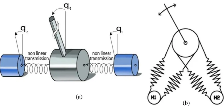
Bicchi et al. (2005) developed a new design of variable stiffness actuator (VSA) in their lab, as seen in Figure 2.4. Two independent brushless controlled motors are used, connected by a trimming belt. Passive elastic elements are used to link the VSA cover.
The length of the timing belt (L≈ 0.35 m), is tensioned by the spring constants (k=3 N/m and Km=4 N/m). The position controlled brushless motors are connected to the
pulleys q1 and q2 which are connected non-linearly to the main shaft qm by the timing belt
(Tonietti et al., 2005). The torque capacity for this actuator is limited and it has a limited implementation performance in the robot arm (Schiavi et al., 2008).
2.3.5 Variable stiffness actuator (VSA-II)
[image:36.595.193.404.164.395.2]This new type of actuator is developed by Schiavi et al. (2008) to overcome the limitation on torque capacity and the lack of robot joint performance. The short lifetime for the timing belt which is used in VSA-I, is replaced by four bar mechanisms which provide massive torque and make the actuator more robust. Figure 2.5 illustrates the structure of VSA-II.
14
The transmission system in this actuator aims to provide a nonlinear torque-displacement between the motor torque and the shaft. The desired transmission ratio between input and output is achieved by a suitable design of the four-bar mechanism.
2.3.6 CompAct-VSA
N. G. Tsagarakis et al. (2011) present a new variable stiffness actuator, which is known as CompAct-VSA. The performance of this type of actuator is based on utilising the mechanism of the lever arm with the changeable axis. Figure 2.6 shows the prototype structure of the CompAct-VSA.
[image:37.595.86.524.108.326.2](a)
Figure 2.5 Variable stiffness actuator VSA-II
(a) VSA-II schematic: q1 and q2 are the angle of the motors, q3 is the joint shaft displacement (Schiavi,
Grioli, Sen, & Bicchi, 2008).
(b) The four spring bar configuration of VSA-II (Vanderborght et al., 2013).
15
The stiffness is adjusted by changing the pivot and is achieved in a shorter time, as this actuator uses a short lever arm and small spring to decrease its size.
2.3.7 VSA-CubeBots
[image:38.595.165.460.120.492.2]Catalano et al. (2011) developed a new variable stiffness servo actuator, known as VSA-CubeBots. The word servo applies to the overall system, which is comprised of the
Figure 2.6 CompAct VSA (N. G. Tsagarakis, Sardellitti, & Caldwell, 2011)
(a) The CompAct unit. (b) Lever arm mechanism and variable pivot point diagram. (c) A 3D assembly of CompAct VSA: A) Joint connecting the link and the cam, B)Joint axis, C) Cam shaped lever arm, P) Pivot, E) Cam roller, F)Rack and pinion transmission, G) Motor, and H) Spring.
(a) (b)
16 major mover, the sensors for position control and the electronic board for the control system. Figure 2.7 a photograph of a VSA-Cube.
The small size, the low price, and the high modularity represent the most important design consideration for this actuator (Melo et al., 2014). Catalano et al. (2011) explain that the main advantage of this type of actuator is the low cost which represents one of the important issues in variable stiffness actuation.
2.3.8 Robustness of variable stiffness actuators
[image:39.595.201.434.130.336.2]Wolf and Albu-Schaffer (2013) discuss the mechanical robustness of the variable stiffness actuators, which is defined as the rare probability of risk at a precise situation. This risk is dependent on two main factors: the severity of the consequences and the likelihood of them occurring. For a rigid robot manipulator, adding a spring to the actuator to change its behaviour to be a variable stiffness actuator means adding an additional part to the actuator, which leads to mechanical complexity and the complex behaviour of the spring itself. The VSA robustness is low when it is working at a limited performance. Internal and external risks may affect the robustness of the actuator as well as the robot’s performance.
17 Ozparpucu, Haddadin, Albu-Schäffer, and Center (2014) studied the optimal control for VSA as shown in Figure 2.8 which it constructed using a nonlinear spring to connect the fixed motor to the link.
They presented a novel optimal control method for VSA. The main advantage of this process is the direct physical relation to the system but this method is only applied to one flexible joint and is still open for further research on the multi-joint system (Albu-Schäffer et al., 2010).
2.4
Pneumatic muscle actuator
In recent years there has been a substantial increase in designing, modelling and constructing (biological based) continuum robots (Bartow, Kapadia, & Walker, 2013; Godage, Branson, Guglielmino, & Caldwell, 2012b; McMahan et al., 2006a; McMahan et al., 2005).
The PMA has positives over standard pneumatic cylinders such as the high power to weight ratio, low workspace requirement, flexible structure (Jamwal & Xie, 2012; B.-S. Kang, Kothera, Woods, & Wereley, 2009; Kelasidi, Andrikopoulos, Nikolakopoulos, & Manesis, 2011; Leephakpreeda, 2011; Ranjan, Upadhyay, Kumar, & Dhyani, 2012; Wickramatunge & Leephakpreeda, 2010), infinite degrees of freedom (DoF) (Godage & Walker, 2015; Trivedi, Rahn, Kier, & Walker, 2008; Zheng, Branson III, et al., 2012), variable installation options, no mechanical wear, slight compressed-air consumption, availability of dimension, low cost and robust reliability for human use (B.-S. Kang et al., 2009; Wickramatunge & Leephakpreeda, 2010). A part from these advantages, PMA has been regarded as a suitable substitute for other actuators such as electrical and hydraulic (Anh, 2010; Ranjan et al., 2012). Furthermore, the robot is expected to be safer and more
Motor Load
Nonlinear spring
18 flexible (Davis, Tsagarakis, Canderle, & Caldwell, 2003; Jamwal & Xie, 2012; Wickramatunge & Leephakpreeda, 2010).
Despite its distinct advantages, PMA exhibits highly nonlinear features (Anh, 2010; Jamwal & Xie, 2012; B.-S. Kang et al., 2009; Nakamura & Shinohara, 2007; Szepe, 2011; Thanh & Ahn, 2006; Tondu & Lopez, 2000), which are time dependent. The showing of nonlinearity in the PMA is due to the compressibility of air, the inner tube elastic-viscous properties and geometrically complex behaviours of the PMA outer covering (Jamwal & Xie, 2012; Kelasidi et al., 2011; Wickramatunge & Leephakpreeda, 2010). Moreover, the hysteresis behaviour is caused by the inner tube, which produces different characteristics of PMA during contracting and expanding (Godage et al., 2012b; B.-S. Kang et al., 2009; Leephakpreeda, 2011). This makes the modelling and controlling of pneumatic muscles more difficult (Andrikopoulos, Nikolakopoulos, & Manesis, 2014; Kelasidi et al., 2011; More & Líška, 2013; Ranjan et al., 2012; Wickramatunge & Leephakpreeda, 2010).
Current models do not fully explain every stage of the mechanical performances; therefore an enhanced model is still required (Wickramatunge & Leephakpreeda, 2010). Different models have been proposed to describe the behaviours of the PMAs. Among these models, the Chou and Hannaford model (Chou & Hannaford, 1996) and the Tondu and Lopez model (Tondu & Lopez, 2000) are widely used. These models are based on the assumption of the virtual works of the cylindrical shape and the small thickness of the inner tube (Chou & Hannaford, 1996; Kelasidi et al., 2011; Tondu & Lopez, 2000). Even though there are excellent initial descriptions of the mechanical behaviours, these models are still limited in predicting the performance of the PMA, at least in no-load situations. Furthermore, the force of pulling, length change, air pressure supply, radius and material properties are the major parameters of the PMA. Dynamic performances and the relationships between these parameters differ greatly from one PMA to another.
2.4.1 Structure of pneumatic muscle actuator
19 depends on the amount of air pressure. Figure 2.9 illustrates the structure of the PMA, in addition to the material and parts used to build it.
Where L & D represent the length and the diameter of the air muscle without air pressure and θ is the braided angle, which is the angle between the vertical line and the braided strand (b). The value of this angle varies from 0o to 180o based on the structure and
is a major factor in muscle behaviour.
There is a similarity in behaviour between the human muscle and the pneumatic muscle; they contract by thickening due to the pressure in the inner tube. The Bridgestone Company introduced it again as a rubber actuator in the late 1980s. Since then, the robots are actuated by PMAs especially for medical applications (Ranjan et al., 2012).
2.4.2 Operation of PMA
Kelasidi et al. (2011) and Takosoglu, Laski, Blasiak, Bracha, and Pietrala (2016) explain the principle of operation of the contraction pneumatic muscle under the following conditions: a) varying the input pressure at constant load to determine the isotonic characteristics of the PMA, b) under constant pressure and changing the attached load to find the isobaric characteristics of the pneumatic muscle, and c) the constant contraction ratio operation by changing both the applied pressure and the attached load to determine the isometric performances. The diameter of the braided sleeve will maximize by increasing the air pressure whilst the length of muscle will decrease, additional air will lead to contracting the muscle and increasing in thickness (Ranjan et al., 2012).
L D
Braided angle
20
In Figure 2.10, n is the number of strand turns from end to end of the muscle, which is constant for each muscle. The other parameters (L, D and θ) are changed due to air pressure and the shape of the PMA. In the first case, as is shown in Figure 2.11, PMA is fixed at one end and a constant load is attached to the other end. The gauge pressure gradually increases from zero bar. At a certain pressure value P1, pulling force will develop
and lift the attached load until it reaches the equilibrium point, where the pulling force is equal to the mass weight (Kelasidi et al., 2011).
Vmin
P=0
Lmax
V1
P1
L1
V2
P2
L2
21 At this point, the volume will increase to V1 and the length reduces to L1. Supply more air to the muscle at pressure P2 and it will increase the volume and make the PMA contract more to L2 until the air pressure reaches its maximum value, which depends on the construction of the PMA.
The second operation case is pressurising the PMA at constant air pressure P, then various loads are attached as shown in Figure 2.12.
Reducing the load from M1 will increase the volume and decrease the length of the
muscle (Davis et al., 2003; Kelasidi et al., 2011; Ranjan et al., 2012).
R. Kang, Branson, Zheng, Guglielmino, and Caldwell (2013) argue that in most applications, the PMA is used as a contraction muscle in order to establish a tensile force due to increasing the air pressure, whilst there is another common use in behaviour as an extending mode. Interest in soft robotic manipulators has significantly increased due to their ability to configure with surrounding environments, acting with a wide range of objects which are different in size. The extensor actuators (see Figure 2.13) are related to contractor McKibben actuators; both are operated by supplying air pressure to the rubber tubes encased in a braided sleeve. Where McKibben actuators have a braided angle θ <
V2
P
L2
V1
P
L1
Vmax
P
Lmin
22 54.7o, this resulted in them contracting due to the air pressure, the extensor soft actuators have θ > 54.7o. This type of actuator is extended in length and contract diameter which is
caused by the air pressure (Trivedi, Lotfi, & Rahn, 2008).
2.4.3 Modelling of the PMA
Tatlicioglu, Walker, and Dawson (2007) show that in the most engineering systems it is important to have an accurate model to improve the behaviour of the system. In recent years there has been interesting research done to mathematically model the PMAs. The work was done to relate both the air pressure and the length of PMA to the generated tensile force of contraction muscles. Numerous factors are having major effects on the model, such as the properties of material used in PMA construction, length, diameter, braided angle, air pressure and contraction force. Understanding the relationships between these factors leads to driving accurate models, especially for control requirements (Kelasidi et al., 2011).
Important work was done by Chou and Hannaford (1996). They derived a model for the contraction pneumatic muscle actuator under the following assumptions: (1) the shape of an actuator is cylindrical; (2) there is always a contact between the braided sleeve and the surface of the inner tube; (3) neglecting the friction between the tube and the braided sleeve; and (4) ignoring the latex forces of the tube. Referring to Figure 2.10, the input work (Win) for the McKibben's muscle under air pressure supply is:
θ > 54.7o
Figure 2.13 Extension PMA. (a) Before pressurizing, (b) After pressurizing.
θ > = 54.7o (a)
23 dWin = ∫ (P − Psi 0)dli. dsi = (P − P0) ∫ dlsi i. dsi = PgdV (2.6)
Where P is the absolute pressure, P0 is the environment pressure (P0=1.0336 bar), Pg
is the gauge pressure (the relative pressure), si is the total inner surface, dli is the inner surface displacement, and dV is the volume change. The output work Wout occurs when the actuator shortens with the volume change.
dWin = −FdL (2.7)
Where F is the contractor (tensile) force and L is the axial (actuator) length. Assuming the lossless actuator has no storage energy, the input work must equal the output work, then:
𝑑𝑊𝑜𝑢𝑡 = 𝑑𝑊𝑖𝑛 (2.8)
thus,
−𝐹 𝑑𝐿 = 𝑃𝑔𝑑𝑉
or,
𝐹 = −𝑃𝑔𝑑𝑉𝑑𝐿 (2.9) To evaluate the dV/dL, the authors assumed the braided strand b length was fixed during the pressurizing process. Therefore, the volume of an actuator depends on its length. L and D can be computed as a function of θ.
𝐿 = 𝑏 𝑐𝑜𝑠𝜃 (2.10) 𝐷 =𝑏 𝑠𝑖𝑛𝜃𝑛𝜋 (2.11) Where b and n are constant, the volume of the actuator under cylindrical shape assumption is:
𝑉 =1
4 𝜋𝐷
2𝐿 (2.12)
From equations 2.10 and 2.11: 𝑉 = 𝑏3
4𝜋𝑛2 𝑠𝑖𝑛2𝜃 𝑐𝑜𝑠𝜃 (2.13)
24 𝐹 = −𝑃𝑔 𝑑𝑉𝑑𝐿 = −𝑃𝑔𝑑𝑉 𝑑𝜃𝑑𝐿 𝑑𝜃⁄⁄ = 𝑃𝑔𝑏2(2𝑐𝑜𝑠2𝜃−𝑠𝑖𝑛2𝜃)
4𝜋𝑛2 =
𝑃𝑔𝑏2(3𝑐𝑜𝑠2𝜃−1)
4𝜋𝑛2 (2.14)
Or
𝐹 =𝜋𝐷0𝑃𝑔
2
4 (3𝑐𝑜𝑠2𝜃 − 1) (2.15)
Where: D0 = b nπ⁄ , is the diameter when θ=90o. From this model the maximum
contraction will occur when F=0, and that happen when θ=54.7o.
The second widely used model was made by Tondu and Lopez (2000). Their contraction force formula derived under the following assumptions: 1- The shape of PMA is a perfect cylinder with zero wall thickness. 2- There is a contact between the inner rubber tube and the braided sleeve. 3- The braided strand length is constant. 4- There is no friction between the tube and the sleeve. 5- The latex tube force is neglected. Figure 2.14 illustrates the PMA parameters under initial and pressurized conditions.
Mathematically:
r02+ L 0
2 = b2 (2.16)
r2+ L2 = b2 (2.17)
Where: r0and L0 represent the initial value of actuator radius and length respectively, r and L are the radius and length under pressurizing conditions; the strands length b is constant.
(a)
θ b
r L
θ0 b
r0
L0
(b)
25 And
𝐿0 = 𝑏 𝑐𝑜𝑠𝜃0 (2.18.a)
𝑟0 = 𝑏 𝑠𝑖𝑛𝜃0 (2.18.b) 𝐿 = 𝑏 𝑐𝑜𝑠𝜃 (2.18.c) 𝑟 = 𝑏 𝑠𝑖𝑛𝜃 (2.18.d) Or
𝐿 = 𝐿0 𝑐𝑜𝑠𝜃𝑐𝑜𝑠𝜃
0 (2.19.a)
𝑟 = 𝑟0𝑠𝑖𝑛𝜃𝑠𝑖𝑛𝜃
0 (2.19.b)
From above
𝑟 = 𝑟0 √1−𝑐𝑜𝑠
2𝜃0(𝐿 𝐿 0
⁄ )2
𝑠𝑖𝑛𝜃0 (2.20)
By using the virtual work equation, the contraction force can be written as a function of pressure Pg and the contraction ratio ε:
𝐹(𝑃𝑔, 𝜀) = 𝜋𝑟02 𝑃
𝑔[𝛼(1 − 𝜀)2− 𝛽] (2.21)
Where
𝜀 =𝐿0−𝐿
𝐿0 (2.22)
And
𝛼 =𝑡𝑎𝑛32𝜃
0 (2.23.a)
𝛽 =𝑠𝑖𝑛12𝜃
0 (2.23.b)
Other research is being done to overcome the above assumptions for the presented contractor force models. Tondu and Lopez (2000) modified their model by adding the correction factor (q≤1) as following:
𝐹(𝑃𝑔, 𝜀) = 𝜋𝑟02 𝑃
26 There are two options to select the correction factor: (1) Constant value, which depends on the material and (2) Variable value, which depends on the pressure.
B.-S. Kang et al. (2009) drive a formula to the correction factor as follows:
𝑞(𝑃𝑔) = 1 + 𝑐1 𝑒−𝑐2𝑃𝑔 (2.25)
Where: c1 and c2 are positive constants. From this equation, the correction factor becomes “1” at maximum air pressure, where the actuator shape is cylindrical.
Another work was done by Doumit, Fahim, and Munro (2009) to re-drive the volume formula for the incorrect cylindrical actuator shape. Figure 2.15 illustrates the irregular actuator form at zero pressure.
L0 represents the actuator length, L1 is the horizontal length of the cone, L2isthe cone generator length, φ is the cone angle, L3 is the middle length, D is the middle diameter and d is the ends diameter.
By using (2.11) the diameter is calculated by:
𝐷 =(𝑏
2−𝐿 𝑚 2 )1⁄2
𝜋𝑛 (2.26)
To overcome the contact between inner-tube and braided shell assumption N. Tsagarakis and Caldwell (2000) replaced the gauge pressure Pg by Pa which is equal to:
𝑃𝑎 = 𝑃𝑔− 𝑃𝑟 (2.27)
Where Pr is the (pressure to overcome the radial elasticity of the rubber liner), and it is equal to:
𝑃𝑟 = 𝐾𝑟(𝐷𝑠𝑖𝑛𝜃 − 𝐷0) (2.28) Kr is a constant equal to 20 if D sin θ < 0.033 m. and it is equal to 5 if D sin θ > 0.033 m.
L2
L
L3 L
d D
φ
27 and D0 is the initial diameter.
Wickramatunge and Leephakpreeda (2010) define the force formula as a function of stiffness parameter K and the stretched length Ls, which is defined as the difference between the instantaneous length L and the minimum length at maximum pressure Lu. Figure 2.16 shows these lengths at a certain contraction force.
𝐹 = 𝐾(𝑃𝑔, 𝐿𝑠)𝐿𝑠 (2.27)
K is represented by a polynomial function, which means its parameters are computed from the experimental data for each actuator.
𝐾(𝑃𝑔, 𝐿𝑠) = 𝑐3𝑃𝑔2+ 𝑐
2𝑃𝑔𝐿𝑠+ 𝑐1𝐿2𝑠+ 𝑐0 (2.28)
Furthermore, the authors define a mathematical formula for Lu as a function of gauge pressure as following:
𝐿𝑢 = ℎ2𝑃𝑔2+ ℎ1𝑃𝑔 + ℎ0 (2.29)
Ranjan et al. (2012) presents another force formula as a function of contraction ratio ε. 𝐹 = 12970 (𝑓0𝜀−1+ 𝑓1 + 𝑓2𝜀 + 𝑓3𝜀2) (2.30) The parameters (f0, f1, f2, and f4) are evaluated experimentally by attaching different loads to the actuator and recording ε each time.
Lu Ls
L
F