¡Jo ellllllp^B
EUROPEAN ATOMIC ENERGY COMMUNIT
IP
;
ff
R E F L O S
A CODE FOR THE REFINED EVALUATION
$ÊM;
OF FUEL LOADING SCHEMES
mmßm
W. BÖTTCHER* and E. SCHMIDT*
I t e ' ! ! » ; in co-operation ^ 1 p P ^ ^ | ì ^ P
DE HAAN*, F. HARDT*, J. LIGOU
wm
Sii:
aaeiiiiiiiii
P. TAUCH* and G. VEILHAN »*
* Euratom«f
** GAAA
«
f
"f**'JÍÜBñ|i«'W*i|i
' ';> *i * i-· V'Tri»!"'** !» "llnK lí';'.n'rf''''8w>ji'
'ii ΐ(ΐ18ϋ ^Unibus»' tí* 9 iji'vi' u^mUllBliIi'i
ORGEL Program
I n ! . , * - TVT·» I r t l n n « U Λ Ο Λ / 1 · » / ! M ■ * *-»»■» + /" Joint Nuclear Research Centei
Ispra Establishment Italy
'farit
mm
m
Μ*ΤΜ
IH
d o c u m e n t was p r e p a r e d u n d e r t h e of the E u r o p e a n Communities.
This docui
of the E u r o p e a n c o m m u n i t i e s .
N e i t h e r t h e Commission of t h e E u r o p e a n Communities, its c o n t r a c t o r s nor a n y person acting on their behalf :
Make a n y w a r r a n t y or representation, express or implied, w i t h respect ι t h e accuracy, completeness, or usefulness of t h e information con t a i n e d in this d o c u m e n t , or t h a t t h e use of a n y information, a p p a r a t u s ,
method, or process disclosed in this d o c u m e n t m a y n o t infringe
1
%Iteiu
privately owned rights; OT
S
Assume a n y liability w i t h respect t o t h e use of, or for d a m a g e s resulting from t h e use of a n y information, a p p a r a t u s , m e t h o d or process disclosed in this d o c u m e n t .
This report is on sale a t t h e addresses Usted on cover page 4 ■ "ι ^ Α Γ Ί Ί L'i.î* * Hi^l^HII^Hfll^HHDfUlfi -;βϊΐϊ*ίΐΚ'" miriti f ¡SX
afilli
a t the price of F F 17.50 F B 175. DM 14. Lit. 2 180 Fl. 12.65
W h e n o r d e r i n g , p l e a s e q u o t e t h e E U R n u m b e r a n d t h e t i t l e , w h i c h a r e i n d i c a t e d o n t h e c o v e r of e a c h r e p o r t .
■tipuKijpKtii It 1 "lfll j t t f yytEiWiäoliriu''ivi in P r i n t e d b y G u y o t , s.a.
EUR 4250 e
REFLOS - A CODE FOR T H E R E F I N E D EVALUATION OF FUEL LOADING SCHEMES by W. BÖTTCHER * and E. SCHMIDT *, in co-operation with W. DE HAAN *, F. H A R D T *, J. LIGOU **, P. TAUCH * and G. VEILHAN **
* Euratom ** GAAA
European Atomic Energy Community - EURATOM ORGEL Program
Joint Nuclear Research Center - Ispra Establishment (Italy) ORGEL Project
Luxembourg, April 1969 - 132 Pages - FB 175
REFLOS represents a code for the refined evaluation of fuel loading schemes in heavy water moderated reactors or, more generally, in reactors with weakly absorbing moderator. Its scope is to determine reactivity behaviour, power-distribution, attainable burn-up and fuel cycle cost for both the running-in period and the equilibrium of a power reactor.
EUR 4250 e
REFLOS - A CODE FOR T H E R E F I N E D EVALUATION OF FUEL LOADING SCHEMES by W. BÖTTCHER * and E. SCHMIDT *, in co-operation with W. DE HAAN *, F. H A R D T *, J. LIGOU **, P. TAUCH * and G. VEILHAN **
* Euratom ** GAAA
European Atomic Energy Community - EURATOM ORGEL Program
Joint Nuclear Research Center - Ispra Establishment (Italy) ORGEL Project
Luxembourg, April 1969 - 132 Pages - FB 175
example for input and output.
E U R 4 2 S O e
EUROPEAN ATOMIC ENERGY COMMUNITY - EURATOM
R E F L O S
A CODE FOR THE REFINED EVALUATION
OF FUEL LOADING SCHEMES
by
W. BÖTTCHER* and E. SCHMIDT*
in co-operation with
W. DE HAAN *, F. HARDT *, J. LIGOU **,
P. TAUCH * and G. VEILHAN **
* Euratom ** GAAA
1969
ORGEL P r o g r a m
Joint Nuclear Research Center Ispra Establishment - Italy
absorbing moderator. Its scope is to determine reactivity behaviour, power-distribution, attainable burn-up and fuel cycle cost for both the running-in period and the equilibrium of a power reactor.
REFLOS has been written in FORTRAN IV for the IBM 360/65 computer. The report gives a survey about the methods applied in the individual subroutines of REFLOS, a detailed description of the input parameters and an example for input and output.
KEYWORDS
R-CODES REACTIVITY FUEL ELEMENTS BURNUP
CONTENTS
INTRODUCTION
Pane
THE SUBROUTINE ORACLE 1 θ
1. Scope of the program °
2. Main physical concepts of ORACLE 1 9
3· The heterogeneous constants 15
THE REACTOR CODE 21
1. Principles of the heterogeneous method and assumptions in Trihet 21
2. Modifications of Trihet making it applicable to Reflos 23
THE ECONOMY PART 25
1. Survey about the calculation technique 26
2. Formulae 28
TECHNICAL INFORMATIONS CONCERNING REFLOS 40
1. Identification 40
2. Survey about the construction 41
3· Sequence of the input cards 42
4. Explanation of the meaning of the used symbols for the input 49
5· Output description 92 6. Coding information? 98
SAMPLE FOR INPUT AND OUTPUT 100
1. Problem description 100
2. Print of input and output data 102
REFLOS, a Code for the Refined Evaluation of Fuel
# ) Loading Schemes.
INTRODUCTION**^
REFLOS is a code for the refined evaluation of
fuel loading schemes for heavy water-moderated reactors,
or, more generally, for an heterogeneous reactor containing
a weakly absorbing moderator. It has been developed for
the design calculations for the ORGEL Prototype reactor.
The necessity for its development follows from two points :
a) During the design of the ORGEL reactor a certain
number of nuclear standard codes has been employed.
In order to facilitate their utilization and to
reduce the source oferrors arising by different
definition of the terms, it has been tried to
generate a consistent system of some codes which
are needed to simulate the reactor life.
b) Besides this more technical point of view the
pretensions concerning the quality of the code may
be formulated as follows : if one wants to assess
the potentialities of any reactor system, one will
normally execute simple fuel cycle calculations
applying point models. By means of a typical piece
of fuel of the reactor the isotopie and
reactivity changes are taken into account. But since
nuclear power is becoming progressively more competitive,
*) This work has been performed in co-operation between EURATOM and the "Groupement Atomique Alsacienne Atlantique (GAAA)11 in the frame of the contract EURATOM/GAAA n° 266-66-5 ORG F.
a higher accuracy concerning the economic predictions is needed. One has to take the fuel cycle calculations to the stage where they provide accurate indications of performance attainable in engineering designs. In order
to do this, the non-uniform power distribution in an operating reactor as well as the influence
of the chosen kind of fuel management must be
considered.
REFLOS consists essentially of slightly changed
versions of codes developed at ISPRA, as PLUTHARCO (Ref. l) and RLT-4 (Ref. 2 ) , which have been coupled in ORACLE 1
(Ref. 3) and of the code TRIHET (Ref. 4) (Ref. 5 ) , developed by
GAAA under contract with EURATOM. The part of the code
which governs the fuel movement in the core has been kept quite generally, hence, a lot of imaginable kinds of radial
fuel management schemes can be investigated, namely all combinations of :
batch re-loading or continuous (element-wise) re-loading ;
movement of the fuel from outside to inside of the core or vice-versa;
inversion of the re-loading scheme on the edge of two neighboring core zones or no inversion.
evaluated. Having as input parameters the re-loading plan and the desired power, REFLOS could be taken as a
tool for the automatic control for the fissionable materials fed in, and discharged from, a power station. This can be also done for small operation intervals of the reactor, because the mass balances are given for each re-loading event.
The flow-diagram of REFLOS may be described briefly as follows. ORACLE 1 calculates for at maximum ten different kinds of fuel elements heterogeneous constants as function of the burn-up. The initial reactor state is defined by the spatial distribution of the kinds of fuel and the burn-up rate of the individual fuel element pieces in the reactor core. Then, the flux and power distribution, normalized to the desired total power, is calculated by the aid of the three-dimensional heterogeneous reactor code TRIHET. Assuming a constant flux distribution for a specified time interval, a new burn-up state is defined and the cycle of calculations may be re-started. The surplus reactivity may be compensated by iterating for the depth of control rod insertion into the core. Against this, at present, there is no possibility in REFLOS to simulate the reactor control by moderator poisoning or heating, taking into account the influence of these effects on the spectrum and by this on the conversion rate. This could be important lack in the case of high-reactive initial cores.
The scheme for the re-loading of the fuel elements is described by a matrix what has to be specified by the user. The re-loading is automatically released; if one of the following criteria is fulfilled :
the prescribed life of the reactor is reached;
the effective multiplication factor falls below a specified level;
The fact, that in REFLOS only from outside imposed fuel loading schemes are applicable, is not taken as a serious restriction. After having got some experience referring to the fuel management in the
considered reactor, the user will be able to choose the suitable re-loading plans.
The code is in its application rather variable. Thus, instead to derive the heterogeneous constants by ORACLE 1, one could procure them in any other way and introduce them by punched cards into the code. The program may be used for only one criticality calculation skipping the burn-up part or it may be employed for the investigation of the burn-up behaviour of a reactor
without applying any fuel shuffling. Also the economy part may be omitted, if the knowledge of the corresponding data is not of interest. This variety in the execution of the calculation run is obtained by assembling the single parts of REFLOS by means of AIM-cards. Hence the user may deviate easily from the normal flow diagram of the code.
2. THE SUBROUTINE ORACLE 1
2.1. Scope of the program
9
-The nuclear properties of the lattice cell are changed during the burn-up process by two different effects; firstly, by the alternation of the isotope densities of the heavy atoms and of the reactor poisons itself and, secondly, by the influence of the changement of the isotope composition on the thermal neutron spectrum and by this on the effective microscopic cross-sections for thermal and epithermal neutrons. Corresponding to these two problems a lattice cell burn-up code involves the following stages :
A lattice cell code evaluates the cell reactivity, the heterogeneous constants, the effective microscopic cross sections and other cell parameters for the fresh
uepoisoned fuel. Then the effective cross sections and the isotope composition of this cell state are introduced into a depletion code. After having irradiated the fuel, for a
specified time with a defined flux level*the strongly
absorbing poisons are forced into equilibrium, the new
isotope composition is evaluated and a new lattice calculation will take place. The sequence of cell lattice and depletion calculations is carried out till a prescribed upper limit for the irradiation time is reached.
2.2. Main physical concepts of ORACLE 1
The lattice cellcode
Subsequently, a survey about the physical features
of PLUTHARCO shall be summarized. For more details the
reader is refered to (Ref. l ) .
The effective crosssections are defined by :
where T, g, r, s mean the neutron temperature and the we]1
known Westcottfactors. For Pu¿39 and Pu^40 the svalue
is calculated depending on the corresponding concentrations.
In the case of U230 and Th^3ii s is put equal to zero and
the resonance absorption is evaluated taking into account
correctly the selfsh ielci inu c
The thermal multiplication factor, » , is defined
as the ratio of generated neutrons in fissionable materials
to absorption in the fuel mixture, applying the above defined
crosssections.
For the calculation of Τ the Canadian formula, correlated
to experiments which have been executed with Candu lattices,
may be chosen. Other possible choices are the introduction
of Termidor parameters or spectrum constants derived by any
other technique.
The fast fission factor, £ , is calculated using the
method of Fleishman and Soodak; however, the scheme was
simplified to a twogroups structure instead of a threegroup
one. The two groups are separeted by the fission threshold
of U238. The fission source as well as the source of the neutrons
11
fission and inelastic scattering is not permitted.
Atoms with fissioning capacity beneath the U¿38 fission
threshold are corrected for the fact that subthreshold
fissioning is not permitted, i.e., the fast fission in
the second group is added to the first one.
The calculation run for the resonance escape pro
bability can be divided into three parts. First, the
effective surface per gram of fuel for the cluster is
evaluated by the method of Hellstrand. After having
derived this, the cluster is identified with an effective
rod with the same surface per gram and the resonance
integral, I, is calculated by :
if?
interpolating tables which give A and Β as function of the
physical temperature and the composition of the fuel. A and
Β have been derived by fitting of resonance integrals calculated
by the aid of the method of Nordheim. Finally, the resonance
escape probability, p , is calculated by taking into account
the disadvantagefactor of the epithermal flux, what results
from the heterogeneous buildup of the lattice cell.
The thermal utilization factor, f, is evaluated by :
f
. f
f C cc
where f^ represents the fuel to cluster utilization factor f c
and f the cluster to cell utilization factor. Both factors
are calculated following the proposals of Amouyal and Benoist. For calculating f the lattice cell is
cc
approximated by a cylindrical homogeneous fuel zone at the center,being surrounded by five cylindrical regions: outer coolant, pressure tube, insulating gap, calandria tube and moderator.
2
The diffusion area for the lattice cell, L , follows 2
from the diffusion area of the moderator, L , and from the m
diffusion area of the central non-moderator region, L : c
2 2 , ν 2
L = L (1 - f) + fL m c
The slowing-down area of the moderator Τ is m
automatically corrected for the perturbation of the fission spectrum by inelastic scattering in the fuel and for the presence of hydrogen atoms.
In (Ref. l) an extensive conformation of PLUTHARCO results and experiments (EXPO, Cise, Savannah River, Chalk River) has been described. Generally, the four factors of the four-factor-formula were in good agreement with the
measurements. Against this, remarkable discrepancies appeared 2
in L and Τ · The differences in the buckling lay -2
normally within 0.3 m . For small pitches, however, there is a systematic underestimating of the buckling obtained by PLUTHARCO. It is assumed that these discrepancies arise due to inaccuracies in the technique describing the epithermal flux disadvantage factor and due to the fact that the Westcott formalism is no longer appropriate to hardened thermal
13
The depletion code
As depletion subroutine for ORACLE the slightly changed code RLT4 (Ref. 2) has been employed. Thus, it is possible to consider the Uranium burn-up chain. Fop specified products of thermal neutron flux and irradiation time, «>.t, the isotope densities for heavy elements and fission products are calculated. The application of the cross-section
σβ £ ί = ^2200 ( g + r s )
ψΓ
"ίο"""
in the burn-up equations means, that 0 represents the average thermal neutron flux.
The neutron temperature Τ and the epithermal flux fraction r are re-calculated after each irradiation interval
Δ ( 0 t) by means of PLUTHARCO.
In the case of the fertile elements Th-232 and U-238 the cross-sections 6" are corrected for the resonance
absorption defining the effective cross-sections Ç ,
(5=
<J
eff<i + „ >
CO means the ratio of fast and epithermal to thermal
absorptions. It is re-calculated after each irradiation interval <^(0 t ) .
In the depletion code the following heavy atoms are considered :
Th-232, Pa-233, U-233, U-234, U-235t U-236, U-238,
The decay of Pa-233 into U-233 is taken into account by a half-life of 27.4 days. This is the only decay
constant introduced in the burn-up equations. Hence, it is assumed that the (η, Ϋ" )-process in Th-232 leads
instantaneously to Pa-233. Although the neutron absorption
'
l5
n\
in Pa-233 becomes important only at fluxes above 1C \ — ) ,
cm s GC this reaction mechanism is taken into account
assuming an immediate build-up of U-234 and neglecting thus the build-up and decay of Pa-234.
Referring to the uranium-chain it may be shown by comparing the reaction rates released by neutrons with the spontaneous reactions, that the decays of Pu-239i Pu-240 and especially of Pu-24l play an important role in the depletion
calculations anly for fluxes smaller than 10 ( ) . cm s Θ c
Since this is a flux level which will hardly
appear in a power reactor, it is supposed that the neglect of
these decay-mechanism does not represent a significant restriction for the application of the code. It may be still mentioned
that also the delay in the generation of Pu-239, caused by the build-up and decay of U-239 and Np-239 by absorption in U-238, is not taken into account.
The fission products with high absorption cross-sections are treated explicitly in the depletion code. For Sm-l49j Sm-151, Cd-113, Eu-155 and Gd-157 the differential equations are exactly solved while the Xe-135 is always treated to be in equilibrium. The low-cross-section fission products have been collected in three pseudo-fission products following the proposals of the Canadians as Hurst and Walker.
- 15
2.3· The heterogeneous constants
ORACLE calculates the heterogeneous constants by two different techniques applying once an analytical approach and the other time the multi-region theory of Amouyal and Benoist. Since in the past only the
constants derived by the second method has been used, the following explanations shall remain restricted to this theory.
The heterogeneous constants needed in REFLOS are defined by 4 terms :
ALFA 2 1TD 0
a
D, A and 0 mean the diffusion coefficient for thermal a
neutrons in the moderator, the absorption rate in the source region and the asymptotic thermal neutron flux on the edge of the source region.
MU = ALFA χ -τ-Α
Ρ represents the production rate of neutrons.
GAMA
It means the generated power in MW per cm length of the source region and per unit of 0 .
a
BETA
It gives the ratio of mean thermal neutron flux in the fuel
In the multiregion AmouyalBenoist theory the
lattice cell is thought to be divided into a number of
concentric rings. Let n be the number of rings into
which the channel is divided (assuming that the lattice
cell consists of moderator and the channel), f. the th
absorption fraction within the ι ring zone, and Q the
total source of thermal neutrons, then the channel absorption
rate is simply defined as
n
Σ
i = 1f.
If D is taken to be known, the only variable still to
evaluate is the asymptotic flux, in order to determine ALFA.
The direct results of the theory of Amouyal and Benoist
are the neutron streams going in and coming out from the
region i (Í. and 1» , respectively). To obtain the
asymptotic flux, two considerations have been made :
a) It is assumed that the flux on the edge of the
channel can be found by
r- - '. ·
2 (
J ñ ♦ ; ;
which corresponds to an approximation of the
diffusion theory, but using streams derived by
17
b) The flux given under a) can be corrected in order to
obtain the true diffusion theory value using considerations
of (Ref. 7)· It has been found that the moderator to fuel
absorption ratio ( — — 1 ) of the two theories differs
by the term A'f"1» where the result of the integral theory
has to be modified by 0^ m in order to find the diffusion
theory value. It holds
2
V
Äfm
v
y
m m *»·» = m ^m , _J_
2 f Vf f f W a
ι )
and t h u s
vt*
« - ¿ - ( -f-λ - ι )
TTa 2
The subscripts f and m refer to fuel and moderator, respectively.
The term f means the thermal utilization factor of the cell, and
¿, , V, a, A mean the crosssection, the volume per unit of
length, the channel radius and the extrapolation length in terms
of mean free path of the moderator on the edge of the channel.
Introducing the correction for 0 into the formula of a
ALFA, one obtains
ALFA
2 7 r D
2 < r + r
<fn
in
) ♦ - ^ - ( - 3 - λ
- 1 )
r a
2
It may be noted that the discrepancies between the techniques
the single group concept
MU
=
í Ρ*l
f=
k«»
A L F A A A
a n d , c o n s e q u e n t l y ,
M U = A L F A χ k «o
£ Ρ V ψ a r e *h e factors of the fourfactorformula, k ^
means the infinite multiplication factor of the lattice
cell.
The heterogeneous constant GAMA may be written as
GAMA = BETA χ Κ χ dM dz
dM
BETA will be defined below and —: gives the tons of dz
fuel per cm of source length in axial direction. The
specific power per unit of neutron flux within the fuel can
easily be written as
Κ
E
r
f( 1 + Δ )
Vt
where E, ¿ , Û and 0 mean the energy released per fission,
the thermal macroscopic fission cross section of the fuel, the
yield to the fission rate by the fast fission process and the
19
Finally, it remains to evaluate BETA. Taking
again into consideration the n concentrical regions of
the channel, the fuel absorption rate A and the total
channel absorption rate A can be expressed as
i t ,
Σ
t
fi
v
i
ι ^^ 1 a, f
and
n
.Σ, Σ ι. \ .
1 = 1 a ' i i
We are looking for the reaction rate in the fuel per unit
of neutron flux on the surface of the channel
Af = Af
0,
0.
2 TTD χ ALFAThe neutron flux ratio BETA on its turn is related to this
term by
0.
= BETA χη
Σ .
Σ
V = BETA χi = 1 a,f i a,f f
and thus
BETA
£ Ç,
Ά-
1ν
f
1ø
1 1 -1 VX AT 2 D χ ALFA
The parameter A can be found as
Σ
Σ *<*
f
i=l i i
and A is equal to the sum of the f. for the individual regions within the channel.
Hence the generalized formula for BETA reads :
n
£
t
Σ
a,f\ —
f,1 = 1
t
*
BETA = : r x x 2 TTD χ ALFA
i=l a,f i=l
For a single region of the channel this expression may be simplified to
2 TTD χ ALFA χ f BETA =
(ι
-
t
) V
.Γ
m f a, f
21
THE REACTOR CODE
The choice of TRIHET (Ref. 4) (Ref. 5) as a subroutine for REFLOS in order to calculate reactivity
and neutron flux distribution of the considered reactor
was suggested by
its availability at Ispra and the experience
already made with the code ;
the relatively short running-time, taking into
account that TRIHET is a three-dimensional reactor
code ;
the fact that a heterogeneous reactor code facilitates
a suitable simulation of fuel shuffling with
multi--batch or with element-wise re-loading.
Originally, TRIHET has been established for calculations
concerning the test-reactor ESSOR. The basic aspects and the modifications which were made to apply the code in REFLOS
are discussed below.
3·I« Principles of the heterogeneous method and assumptions in TRIHET
Essentially, there are two techniques to treat
heterogeneous reactors. The first one is respented by the
well known unit-cell method of Wigner and Seitz replacing then
the heterogeneous assembly by a partly homogeneous one. The other way to evaluate a heterogeneous reactor has been developed by
thermal neutrons are computed. The thermal neutron flux distribution in the moderator is then calculated by simple diffusion theory. Apart from geometrical data, the influence of the fuel channels on the flux distribution in the moderator is taken into account by the heterogeneous constants, describing the fission and absorption properties of the channel divided by the asymptotic neutron flux on the edge of the channel.
TRIHET represents an extension of the theory of Feinberg and Galanin in so far that the reflector may be considered as finite for thermal neutrons, the slowing-down of the neutrons may be treated by two energy groups, where one of them is governed by age-theory,corrections for the finiteness of the channels have been added and the axial decomposition of the fluxes (expansion of the fluxes in axial direction in Fourier series) has been employed, resulting in a three-dimensional model.
Assumptions representinga certain limitation of the TRIHET code and contained in REFLOS are listed in the
following subsection :
The heterogeneous constants are derived applying the unit-cell model. Consequently, although the thermal flux distribution is calculated later on for the real
heterogeneous assembly, the computation is not heterogeneous in the stringent sense of the word.
The situation is still worse concerning the resonance absorption. The resonance escape probability is introduced
- 23
calculated in TRIHET. Thus, concerning the resonance absorption, the code does not represent an heterogeneous one.
The reflector must consist of the same material as the moderator.
The fluxes in the two fast groups do not fall down to zero at the outside edge of the reflector but
in infinity. This approximation means that the results of the reactor code will be in good agreement with the reality, if the tickness of the radial reflector amounts
to nearly 4 y f or a greater number. T* is the
slowing-down area.
The fuel channels behave as line sources of fast neutrons. This assumption leads to the requirement that the radii of the channels must not be too great or the channels must not be too closely packed.
The slowing-down properties of the materials within the channel as, e.g., the organic coolant, are not treated separately but must be included in a suitable way by
modifying the slowing-down behaviour of the moderator.
3-2. Modifications of TRIHET making it applicable to REFLOS
The necessary informations,which must be provided by the subroutine TRIHET, are :
the k for the given reactor state or the position ef f
the specific power for each fuel element channel at j points along the channel in units of , MW >
cm
the average specific power for each axial piece of the fuel elements, defined by the j points in units
of /_MW_\ cm
the mean thermal neutron flux in the fuel , n cm s 6 c for each fuel channel at j points within the
channel
the power form factor giving the maximum , MW > divided cm
by the mean , MW > of the reactor.
cm
The formulas for the specific power, together with other items referring to the modification of TRIHET, are described in (Ref. δ ) .
In occasion of the work for REFLOS, some parts of TRIHET have been simplified, reducing so the possibilities of the subroutine to a measure which corresponds to the necessity to evaluate real power reactor. Hence, the
version of TRIHET used in REFLOS can investigate only reactors with axial reflectors and with channels, which are occupied by fuel elements of the same length. The search of criti-cality by varying the absorption rate within the fuel elements has been left out.
25
geometrical data and moderator properties. The terms within the matrix remain constant during all the reactor life and are to evaluate consequently only once. The matrix is fed into Trevol, what takes in consideration the composition of the fuel and, thus, the time-dependent component in a reactoro This feature leads to an appreciable saving of computation time in the case of fuel shuffling investigations.
Secondly, a new symmetry has been introduced, resulting also in a reduction of calculation time, but, and this is of higher importance, also in an increase of the assembly
calculable by the code. In contrast with the old rotation symmetry, the new one represents a specular symmetry, whereat the mirror line is the angle bisector of the sector of the assembly defined by the input. Note that a combination of both symmetries is allowed.
4. THE ECONOMY PART
The scope of this subroutine of Reflos consists of the evaluation of the fuel cycle cost and the consumption of nuclear fuels for the reactor in consideration. In order to contribute to a certain standardization in the field of cost calculations, the applied technique has been based on the procedure established by a group of European firms in co operation and under contract with EURATOM, which is explained in (Ref. 6 ) . In the sense of the terminology of this
reference, the quantities calculated here aré necessarily "a priori costs".
It may be noted that the equilibrium fuel cycle cost of a reactor may be determined with a certain approximation by balancing simply the real credits and expenditures. In the case of the transient period, however, the present-worth method represents the only reasonable technique because there is no proportionality between energy generation (corresponding to credits) and expenditures and, moreover, because the
expenditures occur strongly discontinuously.
4.1. Surveyabout the calculation technique
The course of the calculations is most easily explainable, if one considers the life-time scale of the reactor which is defined by the start-up of the reactor and by charging and discharging events of fuel elements. Mass and composition of the charged and discharged fuel are
determined by the applied loading scheme, the kind of the used fuel and the burn-up rate of the fuel. All these terms are known after having executed the nuclear subroutines and the fuel management subroutine of Reflos.
Because expenditures and credits for the irradiated fuel do not occur directly at the time-point of the loading event, but are rather distributed around it, one has still to investigate the life-time scale of the fuel elements, in order to be able to derive the worth of one kilogram of fuel actualized to the time of the charging or discharging event, respectively. This is done by taking into account the following time intervals of the "history" of the fuel elements :
Transport time for the fresh raw material*·
Fabrication time of the fuel elements.
Waiting time for fresh fuel elements before insertion into the reactor.
In-core time of the fuel elements.
27
Cooling time for fuel elements, which have been discharged from the reactor.
Waiting time for the discharged fuel, in order to accumulate sufficiently great batches for the reprocessing.
Transport time for the irradiated fuel from the reactor to the reprocessing plant.
Time needed for the reprocessing.
Partly, in the above-cited time intervals, many working processes will be summarized. Thus, e.g., during the fabrication time, an eventually necessary conversion of the fuel into the needed form, the pellet sintering and the fuel element fabrication will be done and, during the
reprocessing time, the remaining fuel will be reconverted into a valuable form.
The mass losses of the fuel materials during the individual working processes are taken into account by suitable factors and influence consequently the costs. The costs for the first core may be weighed by the excess elements on reserve«
It is possible to introduce a tax-rate on the worth of the capital bound in the fuel cycle. This tax-rate is paid for the half of the fuel element life on the worth of the fresh element and for the other half of the life on the worth of the discharged fuel.
After having derived such values for one kilogram of fresh and irradiated fuel, the total expenditures and credits per reloading event are derived multiplying the
specific values by the charged and discharged masses. Then, the total values per reloading event are summed up for
defined as a fraction of the equilibrium period, since this yield will be normally of negligible influence on the total fuel cycle costs extended on the reactor life time.
4.2. Formula
Waiting times (in months) :
If ITWA = 1 and I > 1
In
TWA, .TN
I+IK-1
iSl
DF TN (1+0.01 PM)LIFE (N) 30.4
I+IK-1
L£
DF TN (1+0.01 PM)LIFE (I+IK-1) 30.4
In (1 + 0.01 PM)
If I+IK-1 > Maximum (LIMIT l ) , the calculation of a new
TWA is omitted and the last computed value is employed.
TN and I refer to the table number and to the step of the discharging event.
If ITWE and I > 1
TWE TN
I n
I + I M - 1
mi
I + I M - 1
NT CF N
„„TN
C FN
( 1 + 0 . 0 1 PM)
( 1 + 0 . 0 1 PM)
L I F E ( I ) 3 0 . 4
L I F E (N)
30.4
In (1 + 0.01 PM)
29
If I+IM1 > Maximum (LIMIT l ) , the calculation of a
new TWE is skipped and the last computed value is
used.
Specific cost for enriched or depleted Uraniumf¿n $ ner
K q m e t a l '1 :
KCR^ = (2.6xKYC+KC) . j r p ^ CT
0 . 7 1 1 R 1 0 0 ( 2 y
1 0 0 ) l nI5o^7
_y^R_
0 . 7 1 1 R ( 2 X 0 . 7 1 ! 1 0 0 ) l a ¡ Õ Õ ^ O T T Í I *
*
æk
<- -
«*»
-
Ǥ*
If KCR, < KR , the code puts automatically :
KCR = KR 2
The socalculated value is always used, if BCA is determined.
It is employed for the calculation of BCE only, if the value,
specified in the input, is equal to zero.
Calculation of BCA, BCE ( in $ per Kg metal charged or discharged)
If IRP = O
TN
B C A ; = KL χ (1 + 0.01 PM)
If IRP = 1
BCA *TN (XINU χ W P CI , T N + XINU x W P C1' ™ ) . KCR +
1 1 2 Δ 2
ISØ
K=3
I TN
XINU^ χ W P C ' χ KCR
Κ Κ Λ
BCA TN BCA *TN (WPC1'™ + W P C * ' ™ ) KRC
1 2 . :
ISØ
K=3
WPC^'T N KRC K R PT N KTRT N
Κ
κ
ST TN TN TN
1 ~ Oe«l (TK+TTA+TWA +TRP +05ICTT )
12 I
χ (1.0 + O.Ol PM)
TN
(TK + TTA + TWA + TRP)
TN
The expression within the second bracket of BCA is put TN
automatically zero, if BCA results in a value
3 1
F o r I - LC ( l a s t c o r e )
BCA TN
LC BCA
kTN
LC (WPC
L C»T N , , m ^L C> T N
ISØ " 'i l N + W P C ^ '1 N) K R CO T^~ WPC
JL Cá ¿à ~z—T~~
K = 3
- • ™ , K«CK
TN TN
KRP KTR χ
ST TN
1 —■ O . O l (TK + TTA + TRP + 0 . 5 I C T '" )
1¿4 L C
χ ( 1 . 0 + 0 . 0 1 P M ) " ( T K + T T A + T R P ) +
+ RHØ BCA*™ ( W P CL^T N + W P CL^T N) KRC Σ ^ ( W P C ^1
LC 1 2 2 κ—'i
TN
TN TN
χ K R C l -
■Ò-
KRP - KTRS T
1 — · . O . O l (TK + TTA + TRP + 1 2
+ 0 . 5 χ 1 2 x V I E ) χ ( 1 . 0 + O . O l PM) (TK + TTA + T R P )
BCE' TN = (XIM χ WPC*1 TN 1 + XIM„ χ WPC*1 TN 1 ) KCR„ +
1 1 2 2 2
Υ ΧΙΜ^ χ WPC*' . KCR
If I = 1 (initial core) :
fN „^„xTN
BCE = BCE ι + ST · o.Ol (TTO + T F OT N + TWEOT N + 0 . 5 ICT )
12 λ
TN TN
„ TTO + TFO + TWEO
χ (1 + O.Ol PM) +
NNO ^ T N
3 = 1 NNO
1 + f ' O.Ol (TFO™ ^ § = i + T W E O ™ + 0.5 I C T ™ )
™ ° = 1 T F O ™ + T W E O ™ x (1 + O.Ol PM) N N° *
+ RHØ A BCE ♦TN 1 + — * O.Ol (TTO + TFO + TWEO + 0.5 x 12 χ ςτ TN TN 12
x VIE)
TN TN . TTO + TFO + TWEO
χ (l + O.Ol PK) +
NNO j ^ T N NNO 3 = 1
1 + f | O.Ol (TFO™ χ S = 4
12 NNO1♦ TWEO™ + 0.5 *
χ 12 x VIE) χ ( 1 + O . O l PM)
NNOi TN
' , ' " i TFO + TWEO
NNO1
33
If I > 1 :
„„„IN
BCET = BCE
*TN ST . TN TN TN
1 + —■ O.Ol (TT + TF + TWE + 0.5 ICT* )
la X
TN TN
ι . r, * ™.\ TT + T F + TWE
χ (l + 0.1 PM) +
NIL K F ™ NN j = l
1 + 4 ? O.Ol ( T F ™ M ^ + T W E ™ + 0.5 I C T ™
12 NN1
χ (1 + O.Ol PM)
NNj m„TN „„„TN
NN1
If the expression NN1 becomes zero, it is treated to be 1 TN
during the evaluation of BCE
Calculation of KF TN
TN
If the input value KF is equal to zero, the code evaluates
the following formulas :
WPC if y
WPC + WPC * 100 <( 1.0
.TN
If y ^ 1.0 :
K F ™ ($/kgU) = 76.5 + 0.047 KCR2
Calculation of BKA and BKE :
BKA™ ( S ) D F ™ χ F H A ™ χ B C A ™
TN TN TN TN
B K E ™ ( $ ) = C F JN χ FHA*1" χ Β0Εχ
BKA
(
$ )
= 2
B K A?
N1=1
l
™
TN
BKEI ( $ ) = Υ ΒΚΕχ
Dischargedandcharged materials :
^ T N fj_ χ / ,m oI,TN „„TN „tT.TN
DF I,Κ (to) = ¿__, « WPOTC Κ x DF χ FHA reloaded
axial pieces
E
CF™
( t o )
=
changed
WPC°'™
χ CF™ x FHA™
1 ,Λ. . .. Κ
35
-DMHA™ ( t o ) = DF™ . FHA™
CMHA™ ( t o ) = CF™ . FHA™
DF* (to) =
Σ Ζ
DF™
KK TN Ι=ηχ *l K
CF!! (to) =
Σ Σ
CFTK
K TN I=n1 *'K
M varies from 1 to LIM 2.
If M = 1 : ηχ = 1
If M > 1 : η = LIMIT 2 (M-l) + 1
η = LIMIT 2 (M).
Effective expenditures for M intervals of the reactor life
LIFE(I)
BK11 ( $ ) = £ (BKE - BKA ) (1 + 0.01 PM) 3° ' 4
I=ml
The index M varies from 1 to LIM 1.
If M = 1 : ml « 1
If M > 1 ι ml = LIMIT 1 (M-l) + 1
Cost for thefirstçore
BKO ($) = BKM with M = 1 — ^ ml = 1
m2 = LIMIT 1 (l ) = 1
Cost for the transient period of the reactor
BK TRANS ($) = ¿ , BKM - BKO - SU*
M
Cost for one equilibrium period of the reactor
SR* = 81^ M = LIM 1 — »
ml = LIMIT 1 (LIM 1 - l) + 1
m2 = LIMIT 1 ^LIM l)
Duration of one equilibrium period of the reactor
TFEC (days)= LIFE (IE2) - LIFE (iEl)
LIFE (IEl) = LIFE LIMIT 1 (LIM l)
LIFE (IE2) = LIFE LIMIT 1 (LIM 1 - l)
Number of equilibrium periods during the whole reactor life
NEC o VIE x 365 - LIFE (IEl) TFEC
37
Total cost for all equilibrium periods of the reactor
BKG ($) = SR
NEC χ TFEC
1 (1 + 0.01 PM)
* « I. . Λ Λ, ™ i 30.4
_ TFEC
1 (1 + 0.01 PM) 3
NEC LIFE (IEl)
Σ
* TO. 4SR (1 + 0.01 PM) J χ
_ (j 1) TFEC + LIFE (IE2)
χ (1 + 0.01 PM) ■* '
Begin of the runningout period
TXF (days) = LIFE (IEl) + NEC χ TFEC
Cost for the runningout period
τ»*ν L1FE(K) + TXF
IMAX1 „_ Λ
BKR ($) = V*
(
BKE
BKAK
^
+° ·
0 1 PM^
'
K£LI
BKAr„ (1 + 0.01 PM) 1 2 x V I E
Total fuel cycle cost
V a r i a b l e and f i x e d Ç o s t f o r t h e e x t r a p o l a t e d f u e l c y c l e
BCF2 ($) =
LIFE (IEl)
V I E*
I
65 TWEO
* , , 30.4 1 (1+0.01 PM) J
SR (1+0.01 PM) J x
TFEC •JO 4 1 (l+O.Ol PM) J
BCF1 = BCF BCF2
Energy produced in the whole reactor life and discounted to LIFE = 0
12 χ VIE
BE (kWh) Y (1 + 0.01 PM) ~° χ WØRK
3 = 1
Energy produced in the transient period and discounted to LIFE = O
Nyi
BEA (kWh) = V WØRK χ (l + 0.01 P M ) "J + WØRK (y^ Nyl) χ
y
x (l + 0.01 PM) "yi
LIFE (IEl)
1
30.4
39
Energy produced in one equilibrium period and discounted
to the beginning of the equilibrium period
BEG (kWh)
Ny2
V~* (1 + 0.01 P M ) "J WØRK + WØRK (y Ny2) (l + 0.01 PM)"Y1
3 ^
TFEC
y2 30.4
Ny2 = Largest integer of y 2
Fixed specific fuel cycle cost :
— <
H£r
' ■ τ?· ·
lo3
Total specific fuel cycle cost :
BCFl* ( mi1,*r,1S ) = BCF1* + BCF2*
kWh
Specific fuel cost for transition period
RPFF f m i l l s ) BK TRANS + BKO 3 B C F E ( "kWh" ) " BÊÃ ° *°
Specific fuel cost for one_equilibrium period
„~„~ / mills ν
BCFG (
"wnT
}SR (1 + 0.01 PM)
LIFE (IEl) 30.4
BEG 10'
5. TECHNICAL INFORMATION CONCERNING REFLOS
5·1. Identification
Name
IDNumber
Codification
System
Origin
REFLOS (Refined Evaluation of Fuel
Loading Schemes)
68.8125
FØRTRAN IV
IBM 360/65 (300 K)
2 library tapes
2 scratch tapes (disc)
1 calcomp tape
- 41
5.2. Survey about the construction of the code
The following flow-chart shows the subdivision of REFLOS.
PART Cell
1 - ORACLE burn-up by
1
Plutharco - RLT4, performance : writes on tape tables for heterogeneous constants
fuel
burn-and composition in function of -up.
ï
PART 21 - PREVOL
Groups the time-independent computa tions of the TRIHET code;
performance : creation of matrix tape.
ï
PART 22 - STATUS
Reactor burn-up; cycle : core status, interpolation of heterogeneous constants, reactivity by TREVOL (2nd part of TRIHET) fuel management if necessary, new core state; reads ORACLE tape and PREVOL tape, performance : writes fuel cycle data on tape for economical calculation.
ï
PART 3 - CØSTEvaluates the fuel cycle costs for initial core, transition, equilibrium and running-out period; reads fuel cycle data tape.
i
5'3· Sequence of input cards
5-3.4. STATUS
5 -3-3- PREVOL
5-3-2. ORACLE 1
-
43Time card
- 1 card FØRMAT CLØCK 13 Total execution time at disposition of the program
ORACLE 1
- 1 card
AIM1 13 = 0 ORACLE 1 is/was not used; ORACLE 1
data block is omitted ,
- 1 execute ORACLE 1; the appropriate data block follows ,
= 2 don't execute ORACLE 1, ORACLE 1 data block is omitted; previously calculated tables at disposition on tape.
The ORACLE 1 data block is composed of two sets of cards for each calculation (i.e., for each table).
- 1. A set of two identity cards, in which any message may be punched in col. 1-72. This will be printed out on listing before starting the calculation.
- 2. Data cards.
The set-up is as follows (FØRMAT : Al, 2l3i 6F 10.5) :
Col. Any figure (numeric or alfabetical card count.f.i.) may be entered here. An
asteriski*) however must be used only in the
last card of the set, which forms part of
one calculation.
Col. 2-4 The input-list location which will be modified by
the first of the six data fields on the card.
Col. 5-7 The input-list location which will be modified
by the last (between 1 and 6) data field of the card.
Col 8-17 18-27 28-37 38-47 48-57 58-67
>
J
Data fields. The decimal point
may be placed on the places
10 n + 12 (n = 0,5) .
If no decimal points are entered, the point is supposed to be between
col. 10 n + 12 and 10 n + 13 (n = 0,5).
45PREVOL
1 card
AIM21
FØRMAT
IJ
card
ABCl 20A't
1 c a r d
FLDEUX, TAU2, H, R2 H K "12 . o
1 card
NR, NE, KPLEC, IP, KR2, IZNUL, NSYR, NSYE, ΝΤΕ,
IMAT, NANA, NANAI, NANA2, NANA3, ITRI. 1513
(NR NSYR) + (NE NSYE) + NSYR + NSYE cards
AAI, BI, AI, TI, NI 4E12.8, 13
Only if (NSYR + NSYE) not equal O, punch
(NR NSYR) + (NE NSYE) values, 24 per
card
NOS 2413
only if NR not equal O, punch NRNSYR values,
6 per card
HIR 6E12.8
ARIR 6E12.8
ARSR 6E12.8
always present
ΝΤΕ values, 6 per card
NE-NSYE values, b per card
ARIE 6E12.8 ARSE 6E12.8
STATUS FØRMAT
- 1 card
AIM22 13
- 1 card
TAB, UNITI, NR, PRINTl, RUN, UNIT2, PRINT2, PRINT3, PRINT4, PRINT5, PRINT6, CYCLE, PUNCH,
PERFO 1413
- only if CYCLE >1
- 3 cards (j = 1 .... 6)
NUM, TESTI, TEST2, NUM, TESTI, TEST2 2(l6, 2E12.7
N ^ — : Is s \s '*
3=1 3=2
- only if CYCLE > 1
- 1 card
DT EI2.7
- only if CYCLE = 3
- 9 cards
- 47
- always present
- 1 card
NRL, NEL, NTL, IBANAL, IMAT, NCØD, NRM, NANI,
NAN2, NAN3, NAN4 III3
- l card
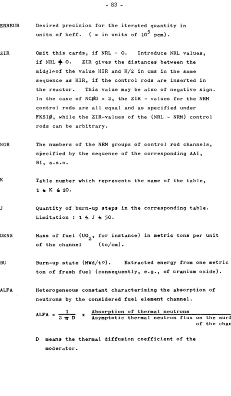
C, FKSIØ, RKSI, DKSI, WTR, ERREUR 6E12.7
- only if NRL > 0
- NRL values, 6 per card
ZIR 6EI2.7
- only if NCØD = 2
- NRM values, 20 per card
NGR 2OI3
- only if TAB = 2
1 card K, J, DENS
► NR times 2I6, EI2.7
5E12.7 J cards
BU, ALFA, MU, GAMA, BETA )
only if TAB = 3
NZ = NEL x (NTL - l) cards
M, ALFA, MU, GAMA, BETA 16, 6X, 4E12.7
only if RUN = 1
1 card
LIFE, FKSIØ 2E12.7
1 card
IMØVE, IP 216
1 to NEL (NTL - 1) cards
CØST
FØRMAT
- 1 card
AIM3 13
1 card
NCALC, TN, ISØ, LIMI, LIM2, ITWE,
ITWA, NN, IRP, NNO 1013
1 card
LIMIT 1 1013
1 card
LIMIT 2 1013
ISØ cards
XINU, KCR, KRC, XIM 4E12.7
TN cards
IK, KRP, KTR, TRP, TWA, FHA 112, 5E12.7
TN cards
IM, KF, TF, TWE, TFO 112, 4E12.7
1 card
TK, TTA, TT, TTO, TWEO 5E12.7
1 card
ST, PM, RHØ, KL 4E12.7
1 card
49
-1 card
KYC, KC, R, CS, KR 4E12.7
only if TN < O
1 card K, J,
1 card
BU, MPL, WPCU235, WPCU, WPCPUFI
1 card
WPC PUFE, WPC TH, WPC U233
J times
213
timas 5E12.7
3E12.7
5.4. Explanation of the meaning of the used symbols for the input
ORACLE 1
1. Compound index for fuel
1. Metal 2. Oxide
3· Monocarbide 4. Dicarbide
7. Other fuel (cross-sections to be entered in NRS 72-89)
2. Diluent spectr. const. (°K)
3.
5· Coolant index 0. Void
1. Gilotherm (Santowax) 2. Diphenyl
3. Heavy water
6. Other organic coolant (data to be entered in NRS 90, 91, 104 and 105)
7. Other coolant (cross-sections to be entered in NRS 137-149 AND I67-I79)
6. Coolant and inner filler spectr. const. (°K)
8. Outer coolant and outer spectr. const. (°K)
10. Pressure tube spectr. const. (ÙK)
11. Insulation index 0. Void
1. Gilotherm (Santowax) 2. Diphenyl
3· Heavy water 4- A 1203
5. Si o2
6. Other organics
7. Other material (cross-sections to be entered in NRS.152-164)
12. Insulation spectr. const. (°K)
13. Occupied (KHET)
-
51-15. Moderator spectr. const. (°K)
16. Physical temperature fuel (°K)
17. Physical temperature coolant (°K)
18. Physical temperature insulation (°K)
19. Physical temperature moderator (°K)
20. -1. Correlated spectr. const. 0. Other spectr. const.
1. Termidor spectr. const, (enter data in NRS. 195-2ΟΟ)
21. Poisoning coefficient, only for irradiated fuel. Absorption in poisoned fuel devided by absorption in unpoisoned fuel.
22. SGR Filler density (Graphite) relative to reference density (I.65 GR/CM3)
23. ALFA, Weight percentage of AL2 03 in SAP (value between 0 and l)
24. RHO-SAP SAP density (in GR/CM3)
25· HBR Percentage of high boiling residues in Santowax (in percents)
26. SAL Effective absorption section (averaged over a maxwellian flux at fuel temperature t(n) due to alloys contained in the fuel.
28. CHW Additional heavy water absorption section due to
impurities other than light water (value at 2200 m/sec).
29. EXSAP Extra absorption in SAP due to impurities (value at 2200 m/sec times 1.0E 5)a
30. S Cylindrical geometry Outer radius of first (outer) tube All other geometries Fuel rod radius
All geometrical data in CM
31. SI 7-Rod Hexagonal 6-Rod Hexagonal l8-Rod Hexagonal 19-Rod Hexagonal 19-Rod Circular 22-Rod
4-Rod Single rod Cylindrical
Clad rod radius Clad rod radius Clad rod radius Clad rod radius Clad rod radius
Radius of central rod Clad rod radius
Cladding inner radius
Inner radius of first (outer) tube
32. S2 22-Rod Single rod Cylindrical
6-Rod (DUMM2) 18-Rod (DUMM3)
Radius of second-ring rods Cladding outer radius
Outer radius of second tube External radius of central tube External radius of central tube
33- S3 22-Rod
Cylindrical 6-Rod (DUMM2) 18-Rod (DUMM3)
Radius of thrid-ring rods Inner radius of second tube Internal radius of central tube Internal radius of central tube
53
35· Al All geometries External radius of pressure tube
36. A2 All geometries Internal radius of calandria tube
37. A3 All geometries External radius of calandria tube
38. R 4-Rod Cylindrical
6-Rod
External radius of central filling Outer radius of third tube
External radius of filler tube
39. OR 4-Rod
Cylindrical 6-Rod (DUMM2)
Thickness of central filling tube (Same composition as cladding) Inner radius of third tube Thickness of filler tube
40. Geometry index for the fuel cluster
-- Comment -- With negative values for these clusters the introduction of the Dancoff correction factor (see Head 126) is supposed.
1. 7-Rod Hexagonal 2. 19-Rod Hexagonal 3. 19-Rod Circular 4. 22-Rod
5. 4-Rod 6. Single Rod
7· 3-Rod geometry 8. Cylindrical
-9· Special geometry (data to be entered in NRS. IO7-I26) 10. 6-Rod geometry
11. l8-Rod geometry
41. 7-Rod Hexagonal
19-Rod Hexagonal
Axial distance from rods in hexagonal geometry
19-Rod Circular
22-Rod
4-Rod
Cylindrical
Axial distance from rods in hexagonal geometry
Distance from center of external ring of rods to center of element Distance from center of element to outer rods
Outer radius of fourth (Inner) tube
42. Dl 22-Rod Cylindrical
Cladding thickness of central rod Inner radius of fourth (Inner) tube
43. D2 22-Rod Cladding thickness of rods in first ring
44. D3 22-Rod
Cylindrical
Cladding thickness of rods in
second ring
Cladding thickness of cylindrical tubes
45. VR Cylindrical
All other geometries
For four rod
Total volume of filling at center 3
of fuel element in cm /cm Total volume of filling Except central filling tube
46. VRIT Cylindrical
All other geometries
47. VRIF Cylindrical
All other geometries
Volume of filling at center of fuel element for calculation of thermal utilisation factor
Volume of filling inside homogenized
central rod for calculation of thermal
Utilisation factor
Volume of filling at center of fuel element for calculation of fast fission factor
OD
4h. Occupied
50. Printing index
0. Output with intermediate results 1. Output without intermediate results
51. Second flight correction Correction factor to make allowance for non-uniformity of neutron density after first collision.
52. Atomic fraction TH-232
53. Atomic fraction U-233
54. Atomic fraction U-235
55· Atomic fraction U-236
56. Atomic fraction U-238
57· Atomic fraction Pu-239
58. Atomic fraction Pu-240
59· Atomic fraction Pu-24l
o
60. Mixed fuel density in G/cra
61. Mixed fuel molecular number
63- Spectr. const. (°K) U-233
64. Spectr. const. (°K) U-235
65. Spectr. const. (°K) U-236
bb. Spectr. const. (°K) U-238
67. Spectr. const. (°K) Pu-239
68. Spectr. const. (°K) Pu-240
b9. Spectr. const. (°K) Pu-24l
70. Lattice cell index 1. VM/VF
2. Square pitch 3· Hexagonal pitch
71. Value of VM/VF (dimensionless) or pitch (cm)
Cross-sections for special fuel (see 1$ Compound index) / l/cm /
72. Absorption (Thermal) (SACT)
73- Fission (Thermal) (SFCT)
74. Scattering (Thermal) (SSCT)
75· Transport (Thermal) (STRCT)
76. Scattering (Epithermal) (SSCE)
5778. Slowing down (Epithermal) (SXSCE)
79. Total
83. Capture
(Fast)
(Fast)
84. Nu times fission(Fast)
(STCF)
80.
81.
82.
Elastic
Inelastic
Fission
(Fast)
(Fast)
(Fast)
(SECF)
(SICF)
(SFCF)
Above the fission
threshold of U238
(SCCF)
(SNUCF <
85. Total 2
87. Capture 2
88. A Res. Int.
89. B Res. Int.
(Fast)
86. Scattering 2 (Fast)
(Fast)
(STCF2) Needed for the evaluation of the fast fission effect
. V for the qroup below the (SSCF2) /
fission threshold of U238
(SCCF2)
(Ul)
(U2)
If RI=A+B
yã/M
U1=N . A . F
U2=N . Β . F / "F f F
F = Atomic fraction
0 = density
Ν = Atoms/cm
90. Organic density at 0 centigrade (see 5. Coolant index)
3
6/ cm
91. (Density temp, coeff.Hirnes 1.E4 (see 5· Coolant index)
94. I
V Not occupied
95-J
96. Table-number in that the results are to be stored; (* 10) .
If this value is negative, it is set positive and the
tables are also punched on unit 7.
97-i Inter97-ina97-i occup97-ied 102.
103· Not occupied
104. Number of C-Atoms/organic molecule (see 5· Coolant index)
105· Number of H-Atoms/organic molecule (see 5. Coolant index)
IO6.
Geometrical data for special geometry (see 40. Geometry index)
3
107. VC (cm /cm) Volume of combustible in the cell 3
IO8. VG (cm /cm) Volume of canning in the cell 3
109· VO (cm /cm) Volume of coolant in the cell 3
110. VT1 (cm /cm) Volume of pressure tube in the cell 3
111. VT2 (cm /cm) Volume of insulation gap in the cell 3
112. VT3 (cm /cm) Volume of calandria tube in the cell 3
59
-ll4.
115·
3
lió. VBT Volume (cm /cm) included in a rubberband strung around the canned cluster
117. A B T = "yvBT/ir
118. VOIT = VBT - VC - VG
119. VOET = VO - VOIT
3
120. VBF Volume (cm /cm) included in a rubberband strung around the uncanned cluster
121. ABF = yVBF/ir
3
122. VGIF Volume (cm /cm) of can inside of VBF
123. VOIF = VBF - VC - VGIF
2
124. SU Surface (cm /cm) of fuel in the cluster
2
125. SF Surface (cm /cm) of the rubberband as defined for VBF
126. Dancoff correction factor
127. Organic fraction of filler tube holes in 6-Rod clusters
128. Perifericai filler rod center distance to cluster center
130. Max. integrated flux for burn-up ca lculation /~Neutrons/kilobarn_7
131. Step in integrated flux for burn-up calculation /"Neutrons/kilobarnj (maximum : 50 burn-up steps)
132. Actuel integrated flux for burn-up calculation /"Neutrons/kilobarnj
133. Occupied
134. Effective (energy averaged l) thermal neutron flux existing in fuel element (for TH-U233 chain and Xe-equilibrium ·
13 2 in units of 10 n/cm sec).
135.
136.
Cross-section for special coolant (see 5· Coolant index) / l/cm /
I37. Absorption (AT 2200 m/sec) (SANT)
138. Scattering
139. Transport
140. Scattering
l4l. Transport
(Thermal)
(Thermal)
(Epithermal)
(Epithermal)
(SSNT)
(STRNT)
(SSNE)
(STRNE)
l42. Slowing down (Epithermal) (SXSNE)
143. Total
144. Elastic
145. Inelastic
l46. Capture
(Fast)
(Fast)
(Fast)
(Fast)
(STN)
(SEN)
(SJN)
(SCN)
61
-l47. Total 3
l49. Capture 2
(Fast)
l48. Scattering 2 (Fast)
(Fast)
(STN2)
(SEN2)
(SCN2)
Below fission thereshold of U - 238
150.
15I. Occupied
Cross-sections for special insulation (see 11. Insulation
index) / l/cm /
152. Absorption (AT 2200 m/sec) (SANT)
153. Scattering (Thermal)
154. Transport (Thermal)
157. Slowing down (Epithermal)
158. Total
I59. Elastic
I60. Inelastic
I61. Capture
(Fast)
(Fast)
(Fast)
(Fast)
(SSNT)
(STRNT)
155. Scattering (Epithermal) (SSNE)
156. Transport (Epithermal) (STRNE)
(SXSNE)
(STN)
(SEN)
(SJN)
(SCN)
Above the fission threshold
162. Total 2
l64. Capture 2
(Fast)
I63. Scattering 2 (Fast)
(Fast)
(STN2) ^
(SEN2)
(SCN2)
Below the fission
thereshold
of U 238
I65. 166.
Crosssections for special outer_coolant_(see_51_Çoolant_index)
/"l/cm 7
167.
1 6 8 .
169.
170.
1 7 1 .
172.
1 7 3 .
174.
1 7 5 .
Absorption
Scattering
Transport
Scattering
Transport
Slowing down
Total
Elastic
Inelastic
(AT 2200 m/sec)
(Thermal)
(Thermal)
(Thermal)
(Thermal)
(Epithermal)
(Fast)
(Fast)
(Fast)
(SANT)
(SSTN)
(STRNT)
(SSNE)
(STRNE)
(SXSNE)
(STN) "
(SEN)
(SJN)
Above fission
ι thereshold
of U 238
176. Capture (Fast) (SCN)
177. Total 2
179· Capture 2
(Fast)
178. Scattering 2 (Fast)
(Fast)
(STN2)
Below fission
(SEN2) ) thereshold
of U 238
63
180. - 194.
Termidor cross-sections (see 20. Spectral constant index)
195. Spectrum mean microscopic U-235 absorption cross-section
i960 Spectrum mean microscopic U-235 fission cross-section
197o Spectrum moan microscopic PU-239 absorption cross-section
1980 Spectrum mean microscopic PU-239 fission cross-section
1990 Spectrum mean microscopic l/V absorption cross-section/barn (2200m/sec) in fuel
2OO0 Spectrum mean microscopic l/V absorption cross-section/barn (2200m/sec) in moderator
Volume fractions of structural material for canning
201 „ Air
202. Beryliura
203. Graphite
205» Lead
206. SAP
207. Stainless steel
208. Zircaloy-2
Volume fractions of structural_material_for_pressure_tube
211. Air
212o Berylium 213 o Graphite
2l40 Magnesium
215» Lead
216 o SAP
217» Stainless steel
218. Zircaloy-2
219. - 220„ Occupied
Volume fraction of structural material for calandria tube
221. Air
222. Berylium 223. Graphite 224. Magnesium
225. Lead 226. SAP
65
-229.
Occupied
23O0
Volume fractions of structural material for inner filler
231. Air
232. Berylium
233. Graphite
234. Magnesium
235. Lead
236. SAP
237· Stainless steel
238. Zircaloy-2
23 9. - 240. Occupied
Volume fractions of structural material for outer filler
241„ Air
242» Berylium
243. Graphite
244. Magnesium
245. Lead
247ο Stainless steel
248o Zircaloy-2
240. - 250. Occupied
35Ο. If 0, no intermediate results at the individual burn-up steps are printed out; output consists only of input and tables.