Technology (IJRASET)
Low Frequency AC Transmission System
G. Sirisha kumari#1, K. Veerendranath*2, S. Aswak Hussain#3#1
PG Student, Dept.Of EEE RGMCET, Kurnool, AP, India
*2
Assistant Professor, Dept. Of EEE, RGMCET, Kurnool, AP, India
#3
Assistant Professor, Dept Of EEE, RGMCET, Kurnool, AP, India
Abstract— A new Low Frequency AC (LFAC) Transmission System has proposed for transmission of bulk power over long distance by using an intermediate frequency with low investment cost. This paper presents the feasibility of applying low frequency AC transmission technology to interface the wind energy to the main power grid using power electronic devices. The wind power plant is a DC based and connects transmission line with 12-pulse converter. This system is interfaced with main power grid with cycloconverter. This Low Frequency AC Transmission system is implemented with suitable controllers. The system design and control strategies of power electronic devices are discussed and system performances are verified using MATLAB
Keywords— Low Frequency AC (LFAC) Transmission, power transmission, wind energy, 12-pulse inverter, cycloconverter
I. INTRODUCTION
The use of renewable energy resources are gradually increasing such as wind, solar and hydro energy. The wind energy has a significant component of future electric generation due to large space availability and better wind potential. The interconnection and transmission of renewable energy in to main power grid is a major issue. For reliable transmission and interconnection, switching systems have been used to control electrical signals.
Presently, High Voltage AC (HVAC) and High Voltage DC (HVDC) transmission system are well established technologies for transmission of electric power [1]. HVAC system can able to design the protection system and change voltage levels using transformers. The high capacitance of submarine AC power transmission capacity and limits the transmission distance. It is used for short distance transmission for 50-70Km. To overcome the disadvange of HVAC system, HVDC system is developed. Depending on type of power electronic devices used, HVDC system are classified in to Line Commutated Converter HVDC(LCC-HVDC) using thyristor and Voltage Source Converter HVDC( VSC-HVDC) using self commutated devices like insulated gate bipolar transistor. The main advantage of HVDC is that it imposes no limit on transmission distance due to absence of reactive power current in transmission line. LCC-HVDC system is capable to transmit high power up to 1GW with high reliability but it consumes reactive power and introduces lower order harmonics. VSC-HVDC systems are able to regulate active and reactive power exchange. The drawbacks of HVDC system is space charge accumulation, cost of converters and reduced efficiency. This is used for transmission of power for distance greater than 100km.
Due to limitations of HVAC and HVDC systems, High Voltage Low Frequency AC (LFAC) transmission has been proposed as a new alternative technology for transmission of power [2]-[5]. The low frequency AC transmission system utilizes an intermediate frequency for transmission of power. The main advantage of LFAC transmission technology is increase in power transmission capacity over long distance and considerable cost saving due to reduction in cabling requirement, decrease in cable charging current and losses are reduced compared to conventional transmission system. Thus, investment cost and maintenance cost is reduced as well, since frequency converter that synchronizes the frequency between LFAC system and power grid. Also, this system improves voltage stability and no space charge accumulation due to the use of low frequency.
II. LOWFREQUENCYACTRANSMISSIONSYSTEM
The bulk power is transmitted over long distance by using low frequency. The general approach for defining this topology is illustrated in this section.
A. Principle of LFAC system
The active power (P) transmitting over transmission lines are expressed as
P= (VSVR/XL) (1)
Technology (IJRASET)
only way to improve the transmission capability is by reducing the impedance of cable. The reactance of the line is proportional to power frequency and is given as
X=2πf (2)
Where, L is the total inductance over the line, decreasing the electrical frequency can proportionally increase transmission capability. Fig.1 shows the power transmission capability at 50Hz and 20Hz frequency at different cable length. The voltage stability also increases and is expressed as
%∆V= *100 (3)
Where, ∆V is the voltage drop over cable, V is the nominal voltage, Q is the reactive power flow of the cable. Because the impedance is reduced in the LFAC system due to lower frequency, thus voltage drop over the cable is also reduced.
Fig.1. power transmission capability
B. Configuration and operation of LFAC system
Fig.2. configuration of proposed LFAC transmission system
Technology (IJRASET)
with same rated current but only one third of original rated voltage. At the receiving end, a thyristor based cycloconverter is used as an interface between the low frequency side and 60Hz or 50Hz power grid. Thyristor based converters can transmit more power with increased reliability and low cost. However, filters are necessary at both ends to suppress lower order harmonics and to supply reactive power. In summary, LFAC transmission could be an attractive technical solution for medium distance transmission. At the sending end, a medium voltage DC collection bus is formed by rectifying the AC output power of wind turbine [10]. A DC/AC 12-pulse thyristor based inverter is used to convert DC to low frequency (20Hz) AC power. It is connected to a three winding transformer that raises the voltage to a higher level for transmission. AC filters are connected at the inverter side to suppress the 11th, 13th, and higher order harmonics and to supply reactive power to the converter. At the receiving end, a three phase six pulse cycloconverter is used to generate 20Hz voltage. A filter Lf-Cf is connected at the low frequency side to decrease the amplitude of harmonics generated by the cycloconverter.
At the grid side, AC filter are used to suppress odd current harmonics and to supply reactive power to the cycloconverter. The operation of the LFAC transmission system can be understood to proceed as follows. First, the cycloconverter at the receiving end is activated, and the submarine power cables are energized by a 20Hz voltage. In meantime, the DC collection bus at the sending end is charged using power from the wind turbines. After the 20Hz voltage and the DC bus voltage are established, the 12-pulse inverter at the sending end can synchronize with the 20Hz voltage, and initiates the power transmission.
C. Technical benefits of the transmission system
In remote locations and offshore locations, the transmission of energy to main grid is complex. In HVAC systems, interconnecting wind farms with long submarine cables suffers from reactive power requirement due to capacitance of cable and need for inductive compensation, which are not economically feasible, since HVAC cable does not exceed breakeven distance of 50km. In HVDC system, cables do not affect from capacitance and technically feasible for long distance transmission of electrical energy, but this system is more expensive for short and medium distances because of converters cost. Space charge accumulation is present HVDC system, which can be neutralized by increase in frequency higher than 1Hz. Using LFAC transmission, the transmission capability increases by reducing capacitance in the cable, since the impedance is decreases to one third of nominal. Transformers are used to change the voltage levels for transmission, line design and protection systems, which are used in HVAC systems can also used for LFAC transmission system. Thus, LFAC transmission is technically and economically suitable configuration for transmission of power from wind farm to power grid. The investment cost comparison of HVAC, HVDC and LFAC transmission technology is shown in below figure which includes terminal cost and investment cost with respect to the distance [3].
Fig.3. cost comparision of transmission system
Technology (IJRASET)
III.LFACSYSTEMDESIGNANDCOMPONENTSCONTROL
A. System design
The following assumptions are considered for the steady state analysis of LFAC transmission systems.
1) The receiving end is modeled as a 20Hz voltage source of nominal magnitude.
2) The power losses of the reactor, thyristors, filters and transformers are ignored.
3) The resistance and leakage inductance of transformers are neglected.
4) The AC filters are represented by an equivalent capacitance corresponding to the fundamental frequency.
Wind plants are expected to represent a significant component of future electric generation due to greater space availability and better wind potential [6]-[8]. Electric power can be produced from wind energy by using wind turbine generator. The maximum power extracted from the wind is given as
Pmax = (1/2) CPAV3 (4)
Where, CP is power coefficient, A is the area of wind intercepted by rotor blades, V is the wind velocity.
At steady state, average value of the DC current Idc is equal to Iw. The power delivered from the wind turbine is given as
Pw = Vdc Iw (5)
For 12-pulse converter, the rms value of the current at the transmission side is given as
I = Iw (6)
B. Control of system components
Generating systems cannot be directly connected to power grid systems. Power electronic devices are used for interconnection of renewable energy to power grid for robust and reliable transmission of power. Switching devices can permit to control the electrical signals and change in the voltage and frequency levels. Therefore, in LFAC system at sending and receiving end thyristor based 12-pulse inverter and 6-12-pulse cycloconverter are used for conversion.
1) Sending end control: Thyristor based converters can transmit more power with increased reliability [13]. At the sending
end of the LFAC system, 12-pulse thyristor based inverter is used to generate low frequency AC power. The control structure of an inverter is shown in the fig.5. By adjusting the voltage V at the inverter terminal, the DC bus voltage can be regulated. Cosine wave crossing method is applied to determine the firing angle [14]. Firing pulses are generated by the crossing points of both wanted and threshold voltages of reference voltages. This method establishes superior properties, such as minimum total harmonic distortion of output voltages and simplicity of implementation.
The firing angle for the 12-pulse inverter is given by
αS = (7)
Where VP is the peak value of cosine wave, V*is the reference voltage and αS is firing angle of sending end inverter. For inverter
mode of operation, the voltage is V<0 and 90<α<180. V and Vs are related by
V= VScos(αs) (8)
Technology (IJRASET)
2) Receiving end control: The structure of receiving end controller is illustrated in fig.6. The objective of controller is to provide a constant 20Hz voltage and to modulate frequency, magnitude and phase angle of output voltage. The frequency level is limited to 20Hz because higher frequency can cause distortion. The basic principle of controller is to continuously vary the firing angles of converters. Cosine wave crossing method with circulating current free mode operation is considered for switching sequence. According to the controller algorithm, partial circulating current mode can prevent discontinuous operation during bank exchange function from positive to negative bank with minimal circulating loss. Cosine wave crossing method is used to reduce total harmonic distortion (THD) of output voltages [15].
Fig.6. receiving end control
The fundamental component of cycloconverter voltage is obtained with the signal conditioning block shown in fig.7.
Fig.7. Signal conditioning block
For the positive converter, the positive converter the average voltage at 20Hz terminal is given by
VaP = VGcos(αaP) (9)
Where VG is the rms value of line to neutral voltage at grid, nR is the turn’s ratio of transformers. The average voltages with same
polarity are generated from positive and negative converter at 20Hz terminal [16]. The firing pulses SaP and SaN are not
Technology (IJRASET)
Fig.8. Modular for phase The maximum line to neutral rms value of 20Hz cycloconverter voltage is given as
= (10)
And, the voltage ratio is defined as
r = (11)
The maximum value r=1 cannot be achieved due to the leakage inductance of transformers which can be ignored.
IV.SIMULATIONRESULTS
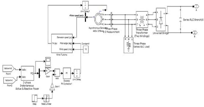
To validate design of LFAC transmission system, simulation is performed by using MATLAB/Simulink software. Control methods shown in fig.5 and fig.6 are applied to control the inverter and cycloconverter. The rating of wind power plant is 180MW which is transmitted over a distance of 160Km. The transmission voltage is chosen as 132kV. The power grid voltage is 132kV line to line. The short circuit level is SSC = 5000MVA, which is typical value for a 132kV system. Simulation results are shown for the 20Hz
LFAC transmission system. The simulink model of wind energy generation and overall system design are shown in fig.9. and fig.10. The steady state line to line voltage and current waveforms at the sending end, the receiving end, the 20Hz side of the cycloconverter and 60Hz power grid under rated power conditions are shown in fig.11
[image:7.612.90.510.451.672.2]Technology (IJRASET)
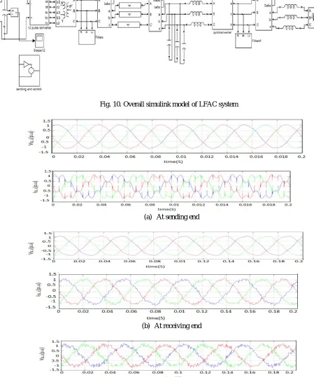
Fig. 10. Overall simulink model of LFAC system
(a) At sending end
(b) At receiving end
Technology (IJRASET)
(c) At cycloconverter
(d) At grid side
Fig.11. Simulated voltage and current wave forms
Fig.12. Transient response
Fig.12 shows the transient response of DC bus voltage at sending end, magnitude of fundamental component of 20Hz voltage generated by cycloconverter, active power injected in to 60Hz power grid, and transmission efficiency.
Technology (IJRASET)
(a) (b)
(c) (d)
Fig.12.FFT analysis of (a) Sending end, (b) Receiving end, (c) Cycloconverter and (d) Power grid
A. LFAC system simulation parameters
1) Transmission line nominal voltage: 132kV
2) Transmission line maximum voltage: 145kV.
3) Transmission line rated current: 825A
4) Cable parameters: resistance 17.6m/km, inductance 0.35mH/km, and capacitance: 0.25 μ F/km.
5) Total wind power: 180MW
6) Transmission line distance: 160km.
7) DC bus capacitance: 1000 μ F
8) Sending end transformer rating: 214MVA, 132/13.2kV, 20Hz
9) AC filters at sending end : 115 MVAr
10) Receiving end transformer rating: 100MVA, 132/88kV
11) AC filters at receiving end : 200 MVAr
V. CONCLUSIONS
Low frequency transmission system (LFAC) is new alternative solution for offshore wind farm. The use of low frequency can improve the power transmission capability because of reduced reactance of the transmission cable and also reduced charging current. In this paper wind power plant is interfaced with power grid using low frequency transmission cables. Design process of Low frequency AC system and its components control are verified by using MATLAB /simulink, and total harmonic distortion has been observed at inverter side, cycloconverter and at power grid. Thus, LFAC system appears to be a feasible solution for medium transmission distance. This is more reliable and cost effective transmission system
VI.ACKNOWLEDGMENT
I would like to like to express special thanks to my advisors K.Veerendranath, Asst.Professor in EEE Dept., RGMCET,
Nandyal, and Andhra Pradesh, India and S.Aswak Hussain,Asst.Professor in EEE Dept., RGMCET,Nandyal, AP, India.I
Technology (IJRASET)
also like to thank my parents and friends who supported me to strive towards my goal.
REFERENCES
[1] N.B. Negra, J.Todorovic, and T.Ackermann, “Loss evaluation of HVAC and HVDC transmission solutions for large offshore wind farms,” Elect. Power Syst. Res, vol76, no.11 pp.916-927,July.2006.
[2] T.Funaki and K.Matsuura, ‟” in proc.IEEE Trans.Power Eng.Soc.Winter Meeting,2000,vol.4,pp.2693-2698. Feasibility of the lower frequency AC transmission, [3] N.Qin,S.You,z.Xu, and V. A,khmatov, “ Offshore wind farm connection with low frequency AC transmission technology," presented at the IEEE Power Energy Soc.Gen.Meeting,Calgary, AB, Canada,2009.
[4] X.Wang,C.Cao,and Z.Zhou, “Experiment with fractional frequency transmission system, IEEE Trans.Power Syst., vol.21, no.1,pp.372-377,Feb.2006.
[5] Y.Cho,G.J.Cokkinides,and A.P.Meliopoulous, “Time domain simulation of a three phase cycloconverter for LFAC transmission system”, presented at the IEEE Power Energy Soc.Transm.Distib.Conf. Expo.,Orlando,FL,May 2012.
[6] M.Lierre,R.Cardenas,M.Molinas, and J.Rodriguez, “Overview of multi-MW wind turbines and wind parks, IEEE Trans. Ind. Appl., vol.43,no.6,pp.1475-1482,Nov/Dec.2007.
[7] C.Meyer, M.Hoing,A.Peterson, and R.W.De Doncker, “ Control and design of DC grids for offshore wind farms”, IEEE Trans. Power Del.,vol.25, no.4,pp.2308-2318, Oct.2010.
[8] J.Yang, J.Fletcher, and J.O’ Reilly, “Multiterminal DC wind farm collection grid internal fault analysis and protection design”, IEEE Trans. Power Del.,vol.25,no.4,pp.2308-2318,Oct.2010.
[9] J.Robimson, D.Jovcic, and G.Joos, “Analysis and design of an offshore wind farm using a MV DC grid”, IEEE Trans.Power Del., vol.25, no.4, pp.2164-2173, Oct.2010.
[10] A.Prasai,J-S.Yim,D.Divan,A.Bendre,and S.K.Sul, “ A new architecture for offshore wind farms,” IEEE Trans.Power Electron.,vol.23,no.3,pp.1198-1204,May 2008.
[11] M.H.Johnson, H.chen, and D.C.Aliprantis. “Offshore wind farm with dc collection system,” IEEE Power Energy Conf., Urbana, IL, Feb.2013. [12] E.Veileux and B.Ooi, “Multiterminal HVDC with thyristor power flow controller,” IEEE Trans.Power Del., vol.27, no.3, pp.1205-1212, July.2012. [13] B.K.Bose, Modern Power Electronics and AC Drives. Upper Saddle River, NJ: Prentice-Hall, 2002