Technology (IJRASET)
©IJRASET: All Rights are Reserved
88
A Design of Dual Band Triangular Microstrip
Patch Antenna for WLAN Applications
Mr.P.Arunagiri1, Naveen Kumar C2, Adhavan K3
1
Assistant Professor, 2,3UG Students, Department of Electronics and Communication Engineering, Sri Manakula Vinayagar Engineering College, Puducherry
Abstract: A triangular microstrip patch antenna is designed to improve the shortcomings of the previous antennas designed in rectangular, square and elliptical shapes such as high return loss and low gain. Dual band is achieved by introducing dual slot to the antenna (i.e. two operating frequencies 5.15–5.35 and 5.725–5.825 GHz are introduced).The compactness of the antenna design is improved by the equilateral shape of the antenna. The gain is enhanced and return loss is reduced by introducing a Koch boundary.
Keywords: Koch boundary, equilateral triangle, ADS 2008, low return loss, high gain.
I. INTRODUCTION
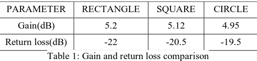
Microstrip patch antennas falls under the category of printed antennas, radiating elements that use printed board to develop the feed and radiating structure. They are inexpensive and easy to design and manufacture because of the 2D geometry. The patch antenna operates in the Ultra High Frequency. In some cases, the dielectric substrate is replaced with a metal patch mounted above a ground plane. This resulted in a rugged structure but can offer higher bandwidth. Enough studies have been made for increasing reliability in WLAN applications. Since microstrip antennas are widely used for WLAN applications, efficient design of the antenna increases the reliability. The available shapes for designing microstrip antenna are rectangular, circular, elliptical, and square. The two major considerations for an efficient antenna are high gain and low return loss. The comparison of gain and return loss parameters of different antenna shapes are given in Table1.
PARAMETER RECTANGLE SQUARE CIRCLE
Gain(dB) 5.2 5.12 4.95
[image:2.612.175.438.420.483.2]Return loss(dB) -22 -20.5 -19.5
Table 1: Gain and return loss comparison
II. LITERATURE REVIEW
C.L.Mak, et.al, [1] had adiscussion on microstrip patch antenna with an inclusion of L-shaped probe. This design is more reliable for thick microstrip antennas when compared with the conventional models. This model enhances the gain to a range of 7 dBi. The radiation pattern is stable throughout the pass band. Guo, et.al, [2] had introduced the design of U-slotted circular patch antenna. The feeding technique was L-probe feeding which results considerable variations in the antenna parameters.The bandwidth of the antenna designed was about 15% wider than the existing U-slotted antennas. The size of the antenna was comparatively reduced by introducing a concept called inverted-F antenna along with capacitive feeding. It was executed by Robert Borowiec, et.al, [3] which operates in triple band frequencies (i.e. GSM 1800, PCS 1900, and UMTS).
Cheng-Jung Lee Leong et.al, [4] proposed a novel approach for compact antenna realization. The mode of propagation was left handed mode. It results in infinite propagation constant at cutoff frequencies. The unit cell optimization results in compact antennas. A wide-band patch antenna was designed by K.L. Lau, et.al, [7] with dual polarization technique. The back of the ground plane is mounted with a directional coupler. It enhances the isolation of L-probe which can be used in communication systems. A Multiband operative Low-Profile Monopole Antenna for Mobile Handsets was proposed by K.L. Wong, et.al, [8]. The above discussed antenna has a rectangular patch in which a folded slit is inserted at the bottom edge.
©IJRASET: All Rights are Reserved
89
A. Advanced Design Software (ADS 2008)
The software used for simulation is ADS (Advanced Design System 2008) software. It affords an integrated design environment to designers of RF electronic products such as mobile phones, optical communication, wireless networks such as wireless radios, satellite systems, RADAR and high-speed data links. Advanced design software supports compact design process along with frequency domain and time domain analysis. It’s widely used in design of wireless, RADAR and satellite applications. It is highly upgradable and flexible for designing an antenna.
The Key features of ADS 2008 are
1) Complete schematic capture and layout environment
2) Innovative , prominent circuit design and system simulators
3) A Direct and native access to 3D planar and full 3D EM field solvers
4) More number of process design kits (PDKs) were established and upheld by leading foundry and industry partners
B. Equilateral Triangle Design
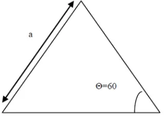
[image:3.612.229.389.333.446.2]The equilateral triangle design yields effective results when compared to the existing shapes. The design becomes more compact by occupying less area and exhibits similar radiation pattern. In this design, the length of the side is calculated using equation (1) and a thickness of t=1.6mm and dielectric constant εr=4.4. An equilateral triangle design is shown in Figure 1.
Figure 1: Equilateral triangle microstrip antenna
=
√ (1)
Where,
a= length of the side of equilateral triangle c= speed of light
εr= Relative dielectric constant of the substrate
The feeding technique used in this design is line feed since it is easier to model and fabricate and easy to match by controlling the inset position.
IV. DESIGN AND SIMULATION RESULTS
A. Design Of Microstrip Patch Antenna
Technology (IJRASET)
©IJRASET: All Rights are Reserved
90
Figure 2: Triangular microstrip antenna
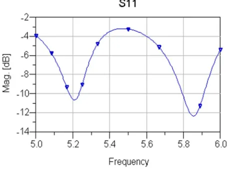
[image:4.612.194.424.287.457.2]The value of return loss for triangular microstrip antenna is measured and the response is shown in Figure 3. The return loss is a measure of impedance matching and it is around -12dB.
Figure 3: Frequency Vs Return loss
[image:4.612.193.430.515.689.2]The gain obtained for different frequencies without Koch boundary is shown in Figure 4. The value of gain is around 5.6dB for the designed triangular microstrip antenna.
©IJRASET: All Rights are Reserved
91
The widely used fractal shape is Koch which exhibits the characteristics correlating with their geometrical properties. Implementing the concept of Koch boundary decreases return loss. Koch boundary can be increased by incrementing the number of iterations. The boundary for different iterations is shown in Figure 5, 6 and 7.
Figure 5: Koch curve with zero iteration (k=0)
Figure 6: Koch curve with one iteration (k=1)
Figure 7: Koch curve with two iterations (k=2)
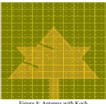
[image:5.612.233.414.325.502.2]C. Microstrip Antenna With Koch
Figure 8: Antenna with Koch
[image:5.612.181.439.576.702.2]The triangular microstrip antenna with the addition of Koch boundary is shown in Figure 8.The return loss and gain for the operating frequencies 5.2 GHz and 5.8 GHz are noted. The addition of Koch boundary enhances the gain and reduces the return loss. The return loss obtained for different frequencies with Koch boundary is shown in Figure 9. The value of return loss for triangular microstrip antenna with Koch is measured. The value is reduced upto -38dB.
Technology (IJRASET)
©IJRASET: All Rights are Reserved
92
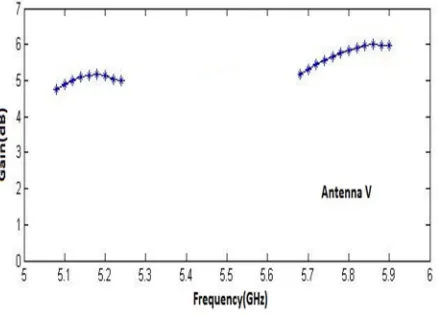
[image:6.612.200.419.129.287.2]The gain has also been increased to about 5.5dB at 5.2 GHz and 6.2dB at 5.8 GHz by introducing Koch boundary. This is also due to the reason that equal current flow is possible in an equilateral triangle antenna design. The gain at given frequency for the designed antenna has been illustrated in Figure 10.
Figure 10: Frequency Vs Gain
V. CONCLUSION
The antenna proposed has successfully increased the gain to 6.2 dB at 5.2 GHz and 5.8 GHz. The return loss is also considerably reduced to -38dB with introduction of Koch boundary for an equilateral triangle antenna. This makes the antenna more reliable for WLAN applications.
Table 2 clearly indicates that when the Koch boundary is added to the triangular microstrip patch antenna, the return loss is reduced and the gain is increased.
Table 2: Performance comparison of antenna with and without Koch
REFERENCES
[1] R. Kumar Vishwakarma, R. Kumar, “Rectangular notch microstrip antenna for dual-band operation”, International Conference on Recent Advances in Microwave Theory and Applications, 24 Nov. 2008, pp. 675-677
[2] M. Gangopadhyaya , P. Mukherjee ,U. Sharma , B. Gupta , S. Manna, “Design optimization of microstrip fed rectangular microstrip antenna using differential evolution algorithm”, IEEE 2nd International Conference on Recent Trends in Information Systems (ReTIS), July 2015, pp. 49 – 52
[3] K. Brown,“The current distribution on the feeding probe in an air filled rectangular microstrip antenna”, Antennas and Propagation Society International Symposium, June 1989, vol.3, pp. 1680 - 1683
[4] H. Iwasaki, “A circularly polarized rectangular microstrip antenna using single-fed proximity-coupled method”,IEEE Transactions on Antennas and Propagation, Japan ,1995, pp. 895 - 897
[5] M. Harbadji,A. Boufrioua, “Investigation of rectangular multi-band microstrip patch antennas with slots”, 14th Mediterranean Microwave Symposium (MMS), Marrakech, Dec. 2014, pp. 1 – 4
[6] A. A. Deshmukh, D. Vivek , S. Darpan , K. Sagar , K. P. Ray, “Broadband proximity fed modified rectangular microstrip antenna”, International Conference onCommunication, Information & Computing Technology (ICCICT), Mumbai, Oct. 2012, pp. 1 – 5
[7] A. A. Deshmukh, K. P. Ray, “Formulation of Resonance Frequencies for Dual-Band Slotted Rectangular Microstrip Antennas”, IEEE Antennas and Propagation Magazine, 2012, pp. 78-97
[8] Kin-Lu Wong, Wen-Hsiu Hsu, “Broadband triangular microstrip antenna with U-shaped slot”, Electronics Letters, 1997, pp. 2085 – 2087.
[9] Jui-Han Lu,Kin-Lu Wong, Chia-Luan Tang, “Novel dual-frequency and broad-band designs of slot-loaded equilateral triangular microstrip antennas”, IEEE Transactions on Antennas and Propagation, 2000, Volume: 48, Issue: 7, pp. 1048 – 1054
[10] Kin-Lu Wong,Shan-Cheng Pan, “Compact triangular microstrip antenna”, Electronics Letters, 1997, Volume: 33, Issue: 6, pp. 433 – 434
[11] Byoung Moo Lee, Young Joong Yoon, “A dual fed and a dual frequency slots-loaded triangular microstrip antenna”, IEEEAntennas and Propagation Society International Symposium, Salt Lake City, UT, USA, July 2000, vol.3, pp. 1600 - 1603
[12] Jieh-Sen Kuo, Gui-Bin Hsieh, “Gain enhancement of a circularly polarized equilateral-triangular microstrip antenna with a slotted ground plane”, IEEE Transactions on Antennas and Propagation,2003, pp. 1652 - 1656
PARAMETER WITHOUT KOCH WITH KOCH
Gain (dB) 5.6 6.4