Performance Analysis of Aircraft Pitch Control By
Linear Quadratic Regulator and Fuzzy Controller
Surinder Singh1
1
Assistant Professor, Department of Instrumentation, Kurukshetra University, Kurukshetra, India.
Abstract: Today’s aircraft consist of number of automatic controller that helps the airplane crew in airplane management and piloting the aircraft. Usually, the control strategies of aircraft can be grouped into two categories as follows: lateral and longitudinal control. In longitudinal control, the pitch angle has been employed for an aircraft system. Pitch of an aircraft may be described as a rotation around the lateral axis. An elevator is used to control pitch of aircraft which is located at the back of an airplane. So in this paper, a pitch control of an aircraft has been implemented by using Fuzzy controller. The stability of aircraft system is of major concern in real interface system. Thus, aircraft system must be accurate having stable response of aircraft system and should approaches to reference over a certain interval of time i.e. it should not oscillate over a long time. So this work exhibits the design of fuzzy control strategy for controlling the pitch angle of an aircraft. Two control strategies: Linear quadratic regulator (LQR) control and Fuzzy control strategies have been employed and compared. After that a comparative analysis of these control strategies has been done. The whole system has been implemented in MATLAB SIMULINK environment.
Keywords: Pitch control, longitudinal l control, Lateral control, Fuzzy controller, linear quadratic regulator (LQR).
I. INTRODUCTION
Pitch control is a longitudinal control; therefore longitudinal model of an aircraft is used to design the pitch angle controller of an aircraft. Roll control is a lateral control. Therefore lateral model of an aircraft is required to design the roll angle controller of an aircraft. The roll angle is used to control the rolling motion of an aircraft. Elevator is used to control pitch of an aircraft and ailerons are used to control roll of an aircraft. The ultimate aim is to follow the elevator and ailerons command with minimum delay and maximum accuracy. To reduce the complexity of system, assume aircraft as a rigid body and aircraft’s motion consist of a small deviation from its equilibrium flight condition [1]. In addition, the aircraft control system can be divided into two parts, namely longitudinal and lateral control [2]. In longitudinal control, the elevator controls pitch or the longitudinal motion of aircraft system whereas in lateral control lateral motion (roll and yaw) of aircraft system is controlled. Pitch of an aircraft may be described as a rotation around the lateral axis. It might be calculated as the angle between the direction of speed in a horizontal line and vertical plane Pitch of aircraft is control by elevator which usually situated at the rear of the airplane running parallel to the wing that houses the ailerons [3]. Elevator is used to control pitch or to control the tail planes of an aircraft which is located at the back of an airplane. The elevator pivoted at the rear of an aircraft work in pairs; when the right elevator goes up, the left elevator also goes up. The linear zed mathematical model is of third order. Pitch control is a longitudinal problem, and this work presents on design a controller that controls the pitch of an aircraft [4-5]. Lot of research work has been done in the past to control the pitch of an aircraft for the purpose of flight stability and yet this research still remains an open issue in the present and future works [6-7].
This work presents investigation into the development of pitch control scheme by controlling the pitch angle of an aircraft system. A modern controller (LQR) and Fuzzy Controller are developed to control the pitch of an aircraft system. Simulation has been developed in the MATLAB Simulink for evaluation of the both control strategies. Performance of both control strategy with respect to the pitch angle and pitch rate is examined. Comparison of both control schemes to the system performance of aircraft system is presented and discussed.
II. MATHEMATICAL MODEL FOR PITCH CONTROL
The pitch control system considered in this work is shown in Fig. 1 whereXb,Yb andZbrepresent the aerodynamics force
components. θ, Ф and δe represent the orientation of aircraft (pitch angle), orientation of aircraft (roll angle) and elevator deflection
angle in the earth-axis system respectively.
Fig1. Description of pitch control system.
The forces, moments and velocity components in the body fixed coordinate of aircraft system can be described as shown in Fig. 2. The aerodynamics moment components for roll, pitch and yaw axis are represented as L, M and N. The term p, q, r represent the angular rates about roll, pitch and yaw axis while term u, v, w represent the velocity components of roll, pitch and yaw axis. α and β represents the angle of attack and sideslip respectively. In this study the data from General Aviation Airplane [1-2] is used in system analysis and modeling.
Fig2. Definition of force, moments and velocity in body fixed coordinate.
X−mgSθ= m(u̇+ qv−rv)(1)
( )
Z mgC m w pv qu
(2)
M = I q̇+ rq(I −I ) + I (p −r ) (3)
Certain assumptions need to consider solving the aircraft problem: Pitch angle ; θ̇ = qC∅−rS∅
Piching rate ; r =φ̇Cθ−θ̇Sφ
Roll angle ; φ̇ = p + qS∅Tθ+ rC∅Tθ
Rolling rate ; p =∅̇ −φ̇Sθ
aw angle ; φ̇ = (qS∅−rC∅)secθ
Yawing rate ; q =θ̇C∅+φ̇CθS∅
Table1 Longitudinal Stability Derivative Parameters
Longitudinal Derivatives
Dynamics Pressure and Dimensional Derivative Components Q = 36.8lb/ft2, QS = 6771lb,
QSc=38596ft.lb, c/2u = 0.016s
X-Force (S )
Z-Force (F )
Pitching Moment (FT )
Rolling Velocities X =−0.045 Z =−0.369 M = 0
Yawing Velocities X = 0.03 Z =−2.02
Z ̇ = 0
M = 0.05 M ̇ = 0.051
Angle of attack Xα = 0 Xα̇ = 0
Zα=−355.42 Zα̇ = 0
Mα=−8.8 Mα̇ =−0.8976
Pitching rate X = 0 Z = 0 M =−2.05
Elevator Deflection Xδ = 0 Zδ =−28.15 Mδ =−28.15
Equations (1), (2) and (3) should be linearized using small disturbance theory and the variables are replaced as given in (4) by introducing the small perturbation or disturbance.
= +∆ = +∆ = +∆
= +∆ = +∆ = +∆
= +∆ M= +∆ = +∆
= +∆
(4)
For simplicity certain assumptions are taken. First, the reference aircraft conditions are considered to be symmetric and second, the propulsive forces are considered to be same throughout the flight i.e. p = v = r = q = w =φ = 0. After linearization of equations (5), (6), and (7) these are obtained as follows:
− ∆ + (1− ) − ∆ − − − ∆ = ∆ (6)
− ∆ + − ∆ − − ∆ = ∆ (7)
Where X =∂X/∂u/m, X =∂X/∂w/m etc. are aerodynamic derivatives divided by the airplane mass. By solving the (5), (6), (7) and putting the longitudinal stability derivatives parameter values from Table I, the transfer function for ∆q(s) to ∆δ (s) is shown as obtained in (8), where ∆q(s) represent the variation in pitch rate and ∆δ (s) represent the variation in elevation rate for pitch control system of an aircraft.
∆ ( )
∆ ( )=
− + ̇ − −
− + ̇ + + −
(8)
The transfer function of variation in pitch angle to the variation in elevator angle can be obtained from the (8) as under.
∆ =∆ ̇ (9)
∆ ( ) = ∆ ( ) (10)
∆ ( )
∆ ( )=
1
∗∆ ( )
∆ ( ) (11)
Thus the transfer function for the aircraft pitch control system is obtained in (12) and (13).
∆ ( ) ∆ ( )= 1 ∗ − + ̇ − − − + ̇ + + − (12) ∆ ( ) ∆ ( )=
11.7304 + 22.578
+ 4.9676 + 12.941 (13)
The transfer function can also be represented in state space form as obtained in (14) and (15).
∆ ̇ ∆ ̇ ∆ ̇
=
−2.02 1 0
−6.9868 −2.9476 0
0 1 0
∆ ∆ ∆ + 0.16 11.7304 0
[∆ ] (14)
= [0 0 1]
∆ ∆ ∆
+ [0] (15)
In the above equations, a Mathematical modeling of Aircraft pitch control system is presented which helps to understand the aircraft system so as to further investigation.
A. Control Methodology
In this section, two control schemes are proposed and described in detail which is Linear Quadratic Regulator (LQR) and Fuzzy Control Scheme. Furthermore, a few of design specification have to be set to investigate the performance of both control strategies. In this work, four considerations have to be met which are rising time less than 3 second, settling time less than 5 second, percentage of overshot less than 10% and steady state error less than 2% for controlling the pitch angle of 0.2 radian (11.5 degree).
B. LQR Controller
Linear-quadratic-regulator (LQR) is a part of optimal control strategy which has been widely developed and used in various applications [10]. LQR design is based on the selection of feedback gains K such that the cost function J is minimized. This ensures that the gain selection is optimal for the cost function specified. The performance index J is defined
Where ‘Q’ and ‘R’ are gain matrices which must be positive semi definite. It is a methodology in modern control system that optimizes the value of performance index J. It uses the feedback control strategy to analyze a system. The system can be stabilized by choosing the proper value of feedback gain K. The feedback control law that minimizes the value of the cost is given by
=− (17) Where K is given by
=− (18)
And the value of P is computed by solving the continuous time algebraic Riccati equation (ARE).
[image:6.612.145.457.230.396.2]+ − + = 0 (19)
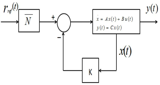
Fig. 3 Full-state feedback controller with reference input.
Pre compensation is used to reduce the steady state error ( ) of the output ( ). Pre compensated gain can be used after the input ( ). Value of gain can be computed using the MATLAB user defined function.Design of LQR controller, it is required to calculate the value of the gain K. it is calculated using algebraic Riccati equation (ARE) by choosing appropriate values of Q and R. The controller can be tuned by varying the value of Q and R matrix by varying matrix to get the desired performance characteristics as shown in fig.3.
C. Fuzzy Logic Controller
Fig.4 Fuzzy logic controller in feedback loop of pitch control system.
Fuzzification involves the conversion of the input and output signal into a number of fuzzy represented values (fuzzy set). Each fuzzy set consists of three types membership function, which is negative (N), zero (Z) and positive (P). The appropriate membership function to represent each fuzzy set need to be defined and each fuzzy set must have the appropriate universe of discourse. In addition, the membership functions are evenly distributed so that the tuning process of the controller can be easily done. In designing FLC, the standard fuzzy rules generated from the under damped response curve. This response is transform into fuzzy rules using the formula obtained below.
( )
( )
( )
e k
r k
y k
( )
( )
(
1)
e k
e k
e k
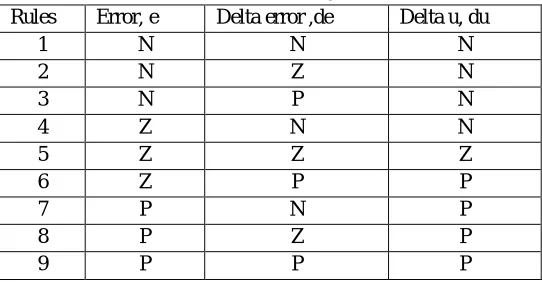
(20)In this work, the triangular membership function is chosen for each fuzzy set. The universe of discourse is set between -15 to 15 and -12 to 12 that implies the range of pitch angle and pitch rate respectively. A two input, one output fuzzy pitch control can be designed by defining error as the reference angle minus the measured angle, and implementing the expert knowledge in a form of If Then rule structure [11]. These are nine rules that have been utilized in designing the controller and the rule is defined in Table 2.
Table 2 Rules for the fuzzy controller
Rules Error, e Delta error ,de Delta u, du
1 N N N
2 N Z N
3 N P N
4 Z N N
5 Z Z Z
6 Z P P
7 P N P
8 P Z P
9 P P P
[image:7.612.171.442.508.649.2]Fig.5 Fuzz set of input (I)
Fig.6 Fuzzy set of input (II)
Fig.7 Fuzzy set of output
In this, a unit step command is required in order for pitch angle to follow the reference value of 0.2 radian = 11.5 degree. Two inputs have been applied to fuzzy logic controller which is the error (e) that computed by comparing the reference point (desired angle) with the plant output and the change of error (Δe) which generated by the derivation of the error. The fuzzy logic controller provides good performance in term of percent overshoot that is 0%. This controller is able to give a good response without produce any overshoot.
III. RESULTS AND DISCUSSION
Table 3 Desired performance specifications
Response Characteristics Pitch angle response
Rising time(T) 1 s
Settling time(T) 0.2 s
Percentage overshoot (%Os) 5%
Steady state error (e %) 2 %
Disturbance rejection (Td) 2s
Design of LQR controller, it is required to calculate the value of the gain K. It is calculated using Riccati equation by choosing appropriate values of Q and R. The controller can be tuned by varying the value of x in Q matrix. The performance characteristics for different values of Q and R are shown in Table 4and Table 5 respectively.
=
0 0 0
0 0 0
0 0
(21)
R= [r] (22)
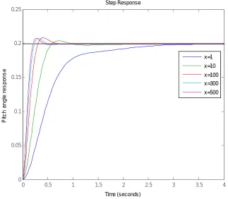
[image:9.612.142.465.433.715.2]As a result, by choosing the different values of x in matrix Q the pitch angle responses are obtained as shown in Fig. 8.The response characteristics for different values of x in Q are shown in Table 4. The response of pitch angle response may improve even more by increasing the value of x in Q.The controller can also be tuned by varying the value of R matrix.
Fig.8 Pitch angle response with LQR for different values of x
0 0.5 1 1.5 2 2.5 3 3.5 4
Table 4 Response Characteristics of LQR controller with different values of x
Response characteristics
Pitch Angle Control
x=1 x=10 x=100 x=300 x=500
Rising time( ) 1.2s 0.36s 0.2s 0.15s 0.132s
Settling time( ) 2.9s 1s 0.435s 0.414s 0.366s
Percentage overshoot (% ) 0 2.24 4.18 4.32 4.35
[image:10.612.120.486.102.499.2]Steady state error (ess%) 0.1 0.01 0.01 0.01 0.01
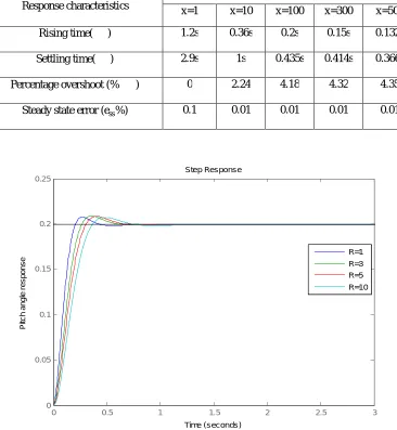
Fig. 9 Pitch angle response with LQR for different values of R
As a result, by choosing the different values R the pitch angle responses are obtained as shown in Fig. 9 and the performance characteristics for different values R are shown in Table 5.
Table 5 Response Characteristics of LQR controller with different values of R
Response characteristics
Pitch Angle Control
R=1 R=3 R=5 R=10
Rising time( ) 0.132s 0.174s 0.198s 0.235s
Settling time( ) 0.366s 0.476s 0.535 0.622
Percentage overshoot (% ) 4.35 4.27 4.18 3.94
Steady state error ( %) 0.01 0.01 0.01 0.01
0 0.5 1 1.5 2 2.5 3
[image:10.612.98.507.582.727.2]The fig.10 shows the pitch angle response with fuzzy logic controller. Two inputs have been applied to fuzzy logic controller which is the error (e) that computed by comparing the reference point (desired angle) with the plant output and the change of error (Δe) which generated by the derivation of the error. The fuzzy logic controller provides good performance in term of percent overshoot that is 0%.
[image:11.612.169.442.345.428.2]Fig.10 Pitch angle response with fuzzy control
[image:11.612.102.515.491.701.2]Table 6 Response Characteristics of Fuzzy Controller
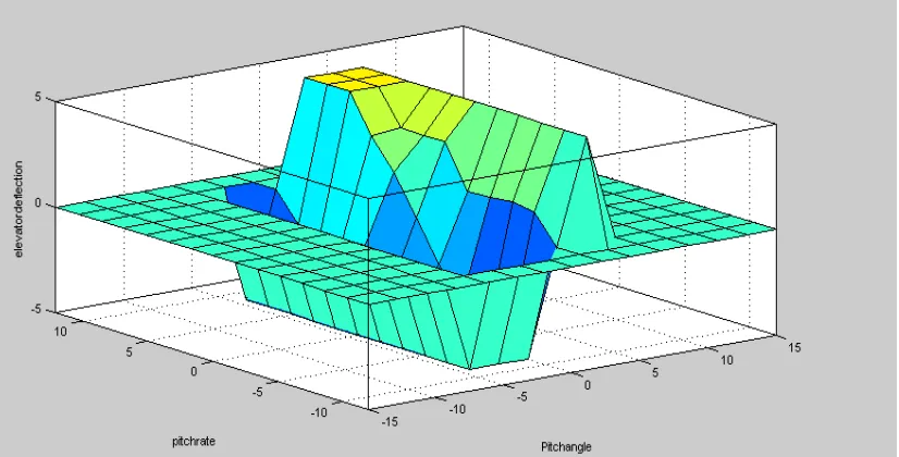
Fig. 11 shows the 3D surface generated as a function of fuzzy set theory which summarizes the rules system. This 3D surface shows the stability of fuzzy controller and satisfied the result evaluated in odd circumstances. The 3D surface in Fig. 11 clearly represents that when two input values are low, the output is also low. The output is gradually increasing in correspondence with the changes in inputs. And an abrupt rise can also be seen when input values are very high.
Fig. 11 Surface Generationin Fuzzy system
0 1 2 3 4 5 6 7 8 9 10
0 0.1 0.2 0.3 0.4 0.5 0.6 0.7 0.8 0.9 1
Time(sec)
P
it
c
h
a
n
g
le
(r
a
d
)
Response Characteristics Pitch angle response
Rising time( ) 1.984s
Settling time( ) 4.232s
Percentage overshoot (% ) 0%
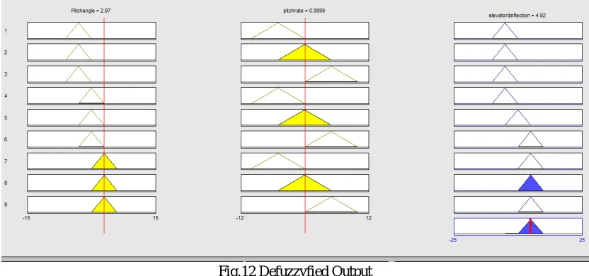
Overall the complete system is minimizing and maximizing in coherence with the input and output values, so it can be summarized that the system is completely balanced and stable. It becomes necessary to evaluate the defuzzyfied results before reaching the final conclusion. Here the Defuzzification has been done, as a deciding element for an appropriate representative value in the final output to find the conclusion. Using his analysis and the obtained defuzzyfied output in Fig. 12, it is possible to obtain results for different combination of independent variables.
Fig.12 Defuzzyfied Output
The performance characteristics of the step response for the pitch angle between LQR and Fuzzy logic controllersare shown in Table 7.
Table 7 Performance characteristic of pitch angle Response Characteristics Pitch angle
LQR (x=100)
Fuzzy Controller
Rising time( ) 0.198 Sec 1.984 Sec
Settling time( ) 0.535 Sec 4.232 Sec
Percentage overshoot (% ) 4.180 0.000
Steady state error ( %) 0.200 0.6452
The LQR and Fuzzy Control strategies are designed successfully. As the performance of these controllers are widely dependent upon the choice of its free parameters such as Q and R matrices for LQR controller. Hence, at last fuzzy controller gives 0% Os, when compared to LQR.
IV. CONCLUSION
The pitch controller of an aircraft is required to stabilize the pitch angle at it desired value. From the comparative analysis of their performance characteristics of the these two controllers for longitudinal pitch angle control of aircraft system it is clear that the Fuzzy Logic Controller gives 0% overshoot as compare to LQR. The LQR controller has better performance as compared to fuzzy logic controller in terms of Rising Time and Settling Time. The LQR controller provides higher ability in controlling the pitch angle as compared to fuzzy logic controller in terms of Rising and Settling time except percentage peak overshoot. Therefore, Both LQR controller and Fuzzy Logic controller are cable to control the pitch angle of the aircraft system.
REFERENCES
[1] G. Alag, and H. Kaufman, “An implementable digital adaptive flight controller designed using stabilized single-stage algorithms” IEEE Transactions on Automatic Control, vol. AC-22, no.5, pp. 780-788, 1979.
[2] Robert C. Nelson, Flight Stability and Automatic Control, McGraw Hill, Second Edition, 1998
[image:12.612.141.469.397.501.2][4] Chen, F.C. Khalil, and H.K., “Two-Time-Scale Longitudinal Control of Airplanes Using Singular Perturbation’’, AIAA, Journal of, Navigation, and Control, vol. 13, no. 6, pp. 952-960, 1990
[5] Sundararajan, Y., Li, N., &Sratchandran P.,“Neuro-controller design for nonlinear fighter aircraft maneuver using fully tuned RBF networks”, Automatica,Vol. 37, pp. 1293–1301, 2001
[6] Thomas J. Redling, “Integrated Flight Control System; A New Paradigm for an Old Art”, IEEE Aerospace and Electronic Systems Society (AESS) Systems Magazine, 200
[7] B. Stojiljkovic, L. Vasov, C. Mitrovic, D. Cvetkovic, “The Application of the Root Locus Method for the Design of Pitch Controller of an F-104A Aircraft”, Journal of Mechanical Engineering, vol. 55, 2009
[8] P.C.Chandrasekharan, “Robust control of linear dynamical systems”, Academic Press, 199
[9] Amir Torabi, Amin AdineAhari, Ali Karsaz, S.H. Kazemi “Intelligent Pitch Controller Identification and Design”, Journal of mathematics and computer science, pp.113-127, 2014
[10] Guo-Ping Cai, Jin-Zhi Huang, and Simon X. Yang, “An optimal control method for linear systems with time delay”, Computers & Structures, vol. 81, no. 15, pp. 1539-1546, July 200