ISSN: 2088-8694, DOI: 10.11591/ijpeds.v7i4.pp1075-1084 1075
Novel Discrete Components Based Speed Controller for
Induction Motor
Hussain Attia1, Ali Sagafinia2
1
Electrical, Electronics & Communication Engineering Dept., American University of Ras Al Khaimah, UAE
2
UM Power Energy Dedicated Advanced Centre (UMPEDAC), University of Malaya, Malaysia
Article Info ABSTRACT
Article history:
Received May 22, 2016 Revised Oct 27, 2016 Accepted Nov 8, 2016
This paper presents an electronic design based on general purpose discrete components for speed control of a single phase induction motor drive. The MOSFETs inverter switching is controlled using Sampled Sinusoidal Pulse Width Modulation (SPWM) techniques with V/F method based on Voltage Controlled Oscillator (VCO). The load power is also controlled by a novel design to produce a suitable SPWM pulse. The proposed electronic system has ability to control the output frequency with flexible setting of lower limit to less than 1 Hz and to higher frequency limits to 55 Hz. Moreover, the proposed controller able to control the value of load voltage to frequency ratio, which plays a major parameter in the function of IM speed control. Furthermore, the designed system is characterized by easy manufacturing and maintenance, high speed response, low cost, and does not need to program steps as compared to other systems based on Microcontroller and digital signal processor (DSP) units. The complete proposed electronic design is made by the software of NI Multisim version 11.0 and all the internal sub-designs are shown in this paper. Simulation results show the effectiveness of electronic design for a promising of a high performance IM PWM drive.
Keyword:
Discrete components design Induction motors
MOSFET PWM inverter V/F ratio
Voltage controlled oscillator
Copyright © 2016 Institute of Advanced Engineering and Science. All rights reserved.
Corresponding Author:
Hussain Attia,
Electrical, Electronics & Communication Engineering Dept., American University of Ras Al Khaimah,
Ras Al Khaimah, 10021, UAE. Email: [email protected]
1. INTRODUCTION
Variable speed motors are used for a wide range of applications where higher performance is needed. These applications include steel and paper drive, variable delivery pumps, cranes, textile industry, and synthetic fiber industry, which are required an adjustable speed capability combined with continuous and accurate speed control [1]-[4].
In case of the DC motors, the commutator consists of a large number of copper segments is separated by thin sheets of mica insulation. This elaborate construction increases the cost of the DC motor and reduces the power/weight ratio [5]. Also, brush and commutator wear by sparking and the mica insulation limits the voltage between segments, which concludes the total armature voltage limitation [6]. Moreover, the magnitude of the armature current and its rate of change are restricted by commutation difficulties, which lead to limitation of the rotation speed [7]. That is why; the DC motor is not the ideal solution for variable speed operation.
applied [11]. Pulse Width Modulation (PWM) is one of the best methods for switching techniques to implement V/F method to keep the constant flux for a full range of speed control of an AC motor drive [12]-[14].
Authors in [15]-[17] have verified their proposed methods with implementation of their work using Microcontroller, Field-programmable gate array (FPGA), and digital signal processor (DSP). The works in [18]-[20] propose artificial neural network based controller, indirect Z-source matrix converter with PSO-PI controller, and PI and Fuzzy controller respectively all for induction motor speed controlling functions. However, these units need to programming steps and also there is a delay in response depending of the controller clock. These points degrade the merits of the systems. In addition, these hardware setups led to higher manufacturing and maintenance cost. Different objectives electronic designs based on discrete components are proposed in [21]-[27] to facilitate and minimize manufacturing and maintenance cost. In the same point of view of using discrete components and to overcome the mentioned problems, this paper proposed a new electronic design based on general purpose discrete components of a single phase AC motor drive with an efficient wide range speed control. The design of this paper is done using NI-Multisim software. All the internal stage design and its simulation results are shown in this paper.
2. RESEARCH METHOD
2.1 System Model
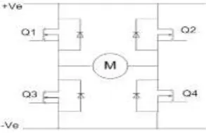
[image:2.595.231.378.369.464.2]In case of a single phase induction motor (SPIM) to avoid variable torque-speed curves when the supply voltage is constant and the frequency is varied, it is necessary to vary the stator voltage proportionally with variation of frequency to obtain constant torque over the frequency range [3]. So, the V/F method is applied for SPIM in this paper as shown in Figure 1.
Figure 1. Configuration of Full H-Bridge for SPIM
The selected PWM technique in this work is unipolar asynchronous sampled sinusoidal pulse width modulation with variable frequency ratio. The variable frequency ratio is obtained through a constant carrier frequency. So, when change the reference frequency inside the controller to control the output fundamental frequency, this lead to a variable frequency ratio (1):
FR = fC / fO (1)
where, FR is the frequency ratio, fC is the carrier frequency (Hz), fO is the reference output frequency (Hz).
Figure 2 shows the block diagram of the proposed system for single phase variable voltage and frequency PWM inverter. The aim of the proposed system is to produce variable frequency and voltage to control the speed of the induction motor.
Figure 2. Block Diagram of the Proposed Induction Motor Drive
2.2 Electronic Design
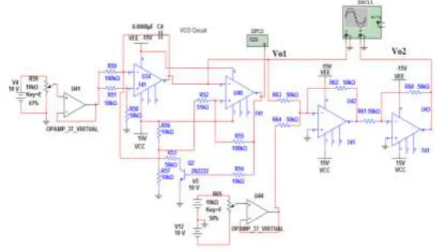
The electronic design completely based on discrete components to provide the additional merits such as, easy constructed, flexible setting, and lower total cost. The design started by the VCO. Figure 3 represents the electronic circuit of the simulated VCO which produce an output frequency range depends on the selected RC included values as well as the value of controlled input voltage.
[image:3.595.164.452.418.550.2]The maximum frequency of the output of the VCO is designed at 2.2 KHz. This frequency enters to the frequency divider and a reference signal generator to have a full wave rectified of a reference sine wave with maximum frequency 55 Hz. The frequency division function is done through the integrated circuit types CMOS4040 with rate of division equal 40 times. The reference signal generator is done through CMOS4017 (Counter), CMOS4066 (Analog Controlled Switches), and Op-Amps (designed as Adder). The voltage controller circuit is designed to add a suitable DC voltage level at low speed range. Figure 4 represents the electronic design to satisfy this increment in the V/F ratio at low speed range.
Figure 3. The Electronic Circuit of Variable Frequency VCO
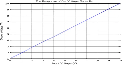
Figure 4. The Electronic Circuit of Set Voltage Controller
Voltage Controlled
Oscillator (VCO)
Frequency Divider &
Decade Counter
Variable Frequency Ref. Signal GeneratorV
Voltage Controller
Voltage Multiplier
PWM Pulses Generator
Gates Drives & Full H-Bridge Vset
0 to 10 V 0 to Max Speed Command
Vfo1: Variable Freq. Fixed Amplitude Vfo2: Variable Freq.
Variable Amplitude Vfo1
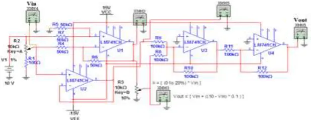
[image:3.595.152.461.603.722.2]The proposed controller is designed to satisfy the following relation between the input voltage (Vin)
to the electronic circuit and output voltage (Vout) from the circuit:
Vout1 = [Vin + (0.1* (10 – Vin))] (3)
The Vout1 enters to one input terminal as a Vin1 of voltage multiplier while the other input terminal
Vin2 is represented by the reference full wave Vfo1. The output value of the voltage multiplier is explained
in (4):
Vfo2 = 0.1 * (Vout1 * Vfo1) (4)
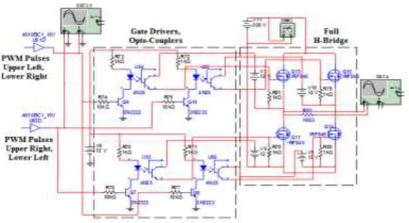
The next stage is represented by PWM pulse generator, which includes two electronic circuits. The first one is a triangular carrier wave oscillator, which is a voltage controlled oscillator. The second electronic circuit is a comparator operational amplifier which used to produce PWM pulses by comparing the high frequency carrier triangular wave with the low range variable frequency reference wave. Figure 5 shows the electronic design of the fixed frequency triangular VCO and the conditional circuit.The last stage in the proposed electronic design is represented by four gate drivers as well as MOSFET (IRF840, 8 A/500 V) transistor full H-bridge. Figure 6 shows the detailed connection of the gate drivers and the MOSFET transistor bridge connected to the DC supply 300 V.
3. RESULTS AND ANALYSIS
This section focuses on the simulation results of all the designed circuits by NI-Multisim software. The recorded results are represented by the shape of all output waveforms and related curves to prove the effectiveness the proposed system. Figure 7 represents the output waveform of the VCO circuit at the control input voltage, which its peak value is 5.1 V. The designed circuit is used to deliver a variable frequency triangular signal to control the output frequency of the proposed system. The high range variable frequency of the VCO output voltage enters to frequency divider to have a lower range of frequency, and it enters also to other circuit to produce samples of a full sine waveform. The maximum input frequency is 2.2 KHz as mentioned in Figure 7.
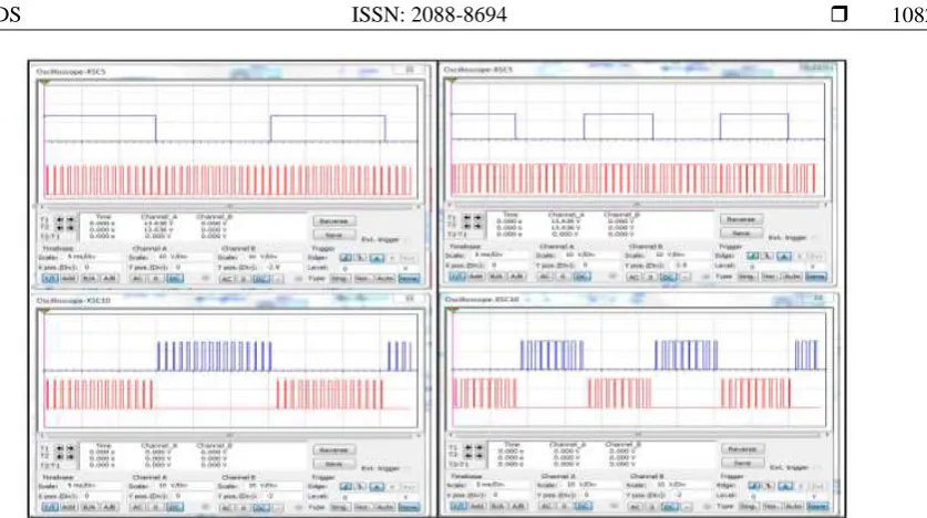
[image:4.595.149.455.554.730.2]Figure 8 shows the behaviour of this circuit through a range of input controlled voltage with maximum value 10 V. From Figure 8, it is found that the linearity of the response, which reflects the high quality of the proposed design. Figure 9 shows the results of the frequency divider, which a half of the maximum reference frequency value and maximum reference frequency are shown, respectively. Figure 9 demonstrates the changing in reference frequency only without change in the amplitude of reference signal. Figure 10 shows the result of the set voltage controller at low speed command. As seen in Figure 10, the input command has an additional suitable DC level. The value of this level is inversely nonlinear proportional with this speed command depend on the desired speed requirement of the IM as shown in Figure 11 for different speed commands. Figure 12 shows full linearity behaviorof the controller.
Figure 6. The Design of Gate Drives and Full H-Bridge
[image:5.595.182.422.458.583.2]Figure 7. The Simulation Result of Variable Frequency VCO at Input Voltage 5.1V
Figure 8. The Behavior of Variable Frequency VCO
As mentioned in Figure 2, the block of voltage multiplier is responsible to multiply the two input values; first one is the output of the voltage controller and the second one is the variable frequency reference signal. Figure 13 shows the result of the output function of this block for medium and maximum speed commands, respectively.
Figure 14 shows the output signal of voltage multiplier compared with fixed frequency carrier (1 KHz) to have the required PWM pulses for medium and maximum speed commands. It is found from Figure 14 that the proposed technique present variable ratios of the carrier frequency to reference frequency which, reflect positively to reduce the torque pulsation at low speed command. Figure 15 shows splitting the PWM pulses for two parts of drive circuits. As seen in Figure 15, the splitting process is done at medium and maximum speed commands. The simulation results of load power at medium and maximum speed commands are shown in Figure 16 and Figure 17 respectively. As seen in these figures, the proposed system
0 1 2 3 4 5 6 7 8 9 10
0.2 0.4 0.6 0.8 1 1.2 1.4 1.6 1.8 2 2.2
Input Voltage (V)
VC
O
O
ut
pu
t F
re
qu
en
cy
(K
Hz
)
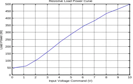
design has ability to control the load power with respect to input speed command. Figure 18 shows the response of the proposed inverter for the transferred power to the resistive load. As shown in the Figure 18, the design shows the effectiveness of the proposed system to have the ability and emulate the practical application.
(a)
(b)
Figure 9. (a) Output Waveform of the Frequency Divider and Reference Signal Generator at Half of Maximum Reference Frequency Value, (b) Output Waveform of the Frequency Divider and Reference Signal
[image:6.595.127.485.155.309.2]Generatorat Maximum Reference Frequency Value
Figure 10. Simulation Results of Set Voltage Controller at Low Speed Command
[image:6.595.141.470.379.539.2] [image:6.595.147.462.583.743.2]Figure 12. Response of the Designed Voltage Controller
(a) (b)
Figure 13. (a) Simulation Result of Voltage Multiplier at Medium Speed Command, (b) Simulation Result of Voltage Multiplier at Maximum Speed Command
Figure 14. Simulation Result of the Comparator at Medium and Maximum Speed Commands
0 1 2 3 4 5 6 7 8 9 10
1 2 3 4 5 6 7 8 9 10
Input Voltage (V)
O
ut
pu
t V
ol
ta
ge
(V
)
[image:7.595.128.482.523.730.2]Figure 15. Splitting the PWM Pulses to Two Parts for Drive Circuits
Figure 16. Splitting the PWM Pulses to Two Parts for Drive Circuits
[image:8.595.126.486.541.721.2]Figure 18. Curve of Resistive Load Power (W)
4. CONCLUSION
An electronic design based on general purpose discrete components for speed control of a single phase induction motor drive has been presented in this paper. The structure of the proposed electronic design is based on the VCO along with a control of the output frequency with a flexible range between 1 Hz - 55 Hz. The load power has been also controlled to produce a suitable SPWM pulse, which has controlled the inverterswitching using V/F method. The proposed electronic design has been successfully simulated and tested using the software of NI-Multisim version 11.0. The obtained results of the proposed electronic design indicate on a promising of high performance IM PWM drive to emulate the practical application. In addition, the proposed discrete components based system has positive merits compare to the other systems based on Microcontroller and digital signal processor (DSP) considering, such as, easy manufacturing and maintenance, low cost, and does not need to programming steps.
ACKNOWLEDGEMENTS
The authors appreciate the financial support provided by school of engineering, American University of Ras Al Khaimah-UAE, www.aurak.ac.ae/en/school-of-engineering/
REFERENCES
[1] Ben, A.H et al.., “Development and experimental evaluation of a sensorless speed control of SPIM using adaptive sliding mode-MRAS strategy”, IEEE J of Emerg and Sel Topics in Power Electron, 2, pp: 319-328, 2014.
[2] Saghafinia, A., et al., “Amindoust A. Teaching of simulation an adjustable speed drive of knduction motor using MATLAB/Simulink in advanced electrical machine laboratory”, Procedia Soc Behav Sci. 103, pp: 912-921, 2013. [3] Arabaci, H., and Bilgin, O. “A novel motor speed calculation method using square wave speed sensor signals via
fast Fourier transform”, Turk J Elec Eng & Comp Sci. 20, pp: 1090-1099, 2012.
[4] Dal, M., and Teodorescu, R., “Sliding mode controller gain adaptation and chattering reduction techniques for DSP-based PM DC motor drives”, Turk J Elec Eng & Comp Sci,19, pp: 531-549, 2011.
[5] Jian, S., and Tie-Cai, L., “New method to eliminate commutation torque ripple of brushless DC motor with minimum commutation time”, IEEE Trans Ind Electron 60, pp: 2139-2146, 2013.
[6] Ayasun, S., “Stability analysis of time-delayed DC motor speed control system”, Turk J Elec Eng & Comp Sci. 21, pp: 381-393, 2013.
[7] Hall, R.D., and Konstanty, W.J., “Commutation of DC motors”, IEEE IndAppl M 16, pp: 56-62, 2010.
[8] Saghafina, A., et al., “Adaptive fuzzy sliding-mode control into chattering-free induction motor drive”, IEEE 2012
Ind Applic Soc., IEEE. pp: 1-8, 2012.
[9] GÖKSU, Ö., and Hava, A.M., “Experimental investigation of shaft transducerless speed and position control of ac induction and interior permanent magnet motors”, Turk J Elec Eng & Comp Sci. 18, pp: 865-882, 2010.
[10] Mahmoudabad, A., et al., “Implementation of an AC model for transmission expansion planning considering reliability constraints”, Turk J Elec Eng & Comp Sci., 21, pp: 1120-1133, 2013.
[11] Saghafinia, A., et al., “High performance induction motor drive using hybrid Fuzzy-PI and PI controllers: a Review”, Int Rew Electr Eng-IREE, 5, pp: 2000-2012, 2010.
[12] Saghafinia, A., et al., “Sensored field oriented control of a robust induction motor drive using a novel boundary layer fuzzy controller. Sensors”, 13, pp: 17025-17056, 2013.
[13] Attia, H., et al., “Design and simulation of a high performance standalone photovoltaic system”, ICREGA’14,
Springer, pp. 683-697, 2014.
0 1 2 3 4 5 6 7 8 9 10
0 50 100 150 200 250 300 350 400 450 500
Resistive Load Power Curve
Input Voltage Command (V)
[14] Abdelkrim, T., et al., “Study and control of 5-level PWM rectifier-5-level NPC active power filter cascade using
feedback control and redundant vectors”, Turk J Elec Eng & Comp Sci., 20, pp: 655-677, 2012.
[15] Saghafinia, A., et al., “Adaptive fuzzy sliding-mode control into chattering-free IM drive”, IEEE Trans Ind Appl., 51, pp: 692-701, 2015
[16] Christopher, I.W., et al., “Microcontroller based single-phase simplified nine-level inverter fed induction motor”,
IICPE, IEEE. pp. 1-6, 2012.
[17] Vinay, K.C., et al.,“ FPGA based implementation of variable-voltage variable-frequency controller for a three
phase induction motor”, Int Conf on Process Automation, Control and Computing (PACC), IEEE, pp: 1-6, 2011. [18] Ashutosh M., and Prashant C., “Artificial Neural Network Based Controller for Speed Control of an Induction
Motor using Indirect Vector Control Method”, International Journal of Power Electronics and Drive System
(IJPEDS), Vol.2, No.4, December 2012, pp. 402~408.
[19] Majid S, and Mohammad S., “Induction Motor Speed Control using Indirect Z-source Matrix Converter with PSO-PI Controller under Various Break Conditions”, International Journal of Power Electronics and Drive System
(IJPEDS), Vol. 3, No. 1, March 2013, pp. 41~52.
[20] R. Gunabalan, and V. Subbiah, “Speed Sensorless Vector Control of Induction Motor Drive with PI and Fuzzy Controller”, International Journal of Power Electronics and Drive System (IJPEDS), Vol. 5, No. 3, February 2015, pp. 315~325.
[21] Attia, H.A., et al., “Design and Simulation of Dual Axis Solar Tracker for Optimum Solar Energy Absorption”,
SDIWC, pp: 144-150, 2013.
[22] Getu, B.N., and Attia, H.A., “Remote Controlling of Light intensity Using Phone Devices”, Research Journal of
Applied Science, Engineering and Technology, 10, (10), pp: 1206-1215, 2015.
[23] Attia, H.A., “Three Steps AC Voltage Regulator Based on One Step-down Transformer”, International Journal of
Applied Engineering Research, 10, (19), pp: 39898-39902, 2015.
[24] Attia, H.A., et al., “Portable Solar Charger with Controlled Charging Current for Mobile Phone Devices”, Int. J. of
Thermal & Environmental Engineering, 7, (1), pp: 17-24, 2014.
[25] Al-Mashhadany, Y.I., and Attia, H.A., “Novel Design and Implementation of Portable Charger through Low Power PV Energy”, Advanced Materials Research, 925, pp: 495-499, 2014.
[26] Attia, H.A., et al., “Experimental validation of DTMF decoder electronic circuit to be used for remote controlling
of an agricultural pump system”, Proceeding of the International Conference on Electrical and Bio-Medical
Engineering, Clean Energy and Green Computing (EBECEGC, 2015), pp: 52-57, 2015.
[27] Attia, H.A., and Getu, B.N., “Design and Simulation of Remotely Power Controller”, International Journal of
Applied Engineering Research, 10, (12), pp: 32609-32626, 2015.
BIOGRAPHIES OF AUTHORS
Hussain Attia earned his M.Sc. degree in electronic engineering from the University of Technology, Baghdad, in 1999. He earned his B.Sc. in electronic and communication engineering from the same university in 1991. M.Sc. Hussain’s research interests include power electronics, AC & DC Speed Control Drives, Electronic Circuits Design, PWM Inverters (single phase & three phases).