Journal of Chemical and Pharmaceutical Research, 2013, 5(12):1200-1208
Research Article
CODEN(USA) : JCPRC5
ISSN : 0975-7384
Dynamic analysis of ultrasonic compound machining system and
microstructure processing
Shao Jian, Zhu Yongwei, Chen Hongzhen, Deng Zhengquan and Wang Fang
Institute of Mechanical Engineering, Yangzhou University, Yangzhou, China
___________________________________________________________________________________________
ABSTRACT
In this paper, by using ANSYS software, dynamic analysis is conducted to ultrasonic vibration machining system including the modal and harmonic response analysis about the transducer and amplitude transformer. Numerical simulation results are compared with the theoretical value, the experimental study of microstructure is completed through ANSYS parametric optimization design. Ultrasonic assisted electrolysis contrast test is completed with microstructures such as arrays of circular pits, Arrays of square pits, PZ Drives.etc through optimized system. The rationality and feasibility of the optimization design for this system is verified. The technical advantages are proved on the basis of parametric optimal design in difficult-to-process materials and special-shaped surface processing through microstructure test.
Key words: Ultrasonic compound system, Dynamic analysis, Amplitude transformer, Optimization design, Microstructure.
_____________________________________________________________________________________________
INTRODUCTION
Electrical conductivity and thermal physical phenomena and so on do not need to be considered in ultrasonic machining, which is compared with electrical discharge machining, electrochemical machining, laser processing. It has a very important role in processing hard-brittle, high-precision materials[1]. The materials are removed because of the high-speed impact of abrasives, which are generated through the ultrasonic vibration of tool in the abrasive suspension. By the compound processing of ultrasonic, spark discharge and electrochemistry, the big loss of tools, low processing speed and etc, such problems can be effectively solved while keeping single processing advantages , also, the problems of hard-tough metal materials and complex shape can be solved. So it has practical significance to research a reliable and efficient ultrasonic machining system in processing and producing high-precision materials. Ultrasonic compound machining system includes: ultrasonic vibratory device, electrolytic device, static pressure adjusting device, electrolytic parameter measuring equipment, etc. [2]. Based on the dynamic analysis of ultrasonic vibration machining system, the best working state is achieved through ANSYS parameter optimization design method. In principle, Every part of system should be at the same frequency to achieve the optimal amplitude of the tool and on this basis to conduct microstructure UECM experiments.
1.DYNAMIC PROPERTIES OF COMPOUND MACHINING SYSTEM
1.1 Modal and harmonic response analysis of transducer
Piezoelectric transducer is adopted in this paper, using the characteristic of deformation while the piezoelectric materials is put in electric field and transforming the electrical oscillation signal of ultrasonic generator into mechanical amplitude. SOLID5 unit is adopted in structure-electric field coupling analysis and defining the material properties and type of unit. SOLID185 unit is adopted in front and back shroud while SOLID5 unit in two pieces of piezoelectric ceramic, the material properties of piezoelectric ceramic PZT4 are defined with command stream. Meshing of transducer is shown in figure 1(a). While medaling, the effect of copper electrode is ignored in order to simplify and assume the modal. The extract method of modals is Block Lanczos and the number of modal to extract is 15. Because the transducer is exposed in the air, zero voltage is exerted to piezoelectric ceramic and let the modal under the short-circuit condition, then the natural frequency and vibration mode of transducer could be solved. The natural frequency of the ultrasonic transducer is 19795 hz by calculating. Vibratory mode of piezoelectric transducer is shown in figure1(b).
[image:2.595.165.450.222.372.2](a) Meshing of transducer (b) Vibratory mode of piezoelectric transducer Fig.1 Dynamic Analysis of Piezoelectric Transducer
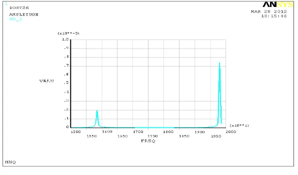
In the process of harmonic analysis, Parallel excitation voltage, which is 600V placed on the piezoelectric ceramic. The ANSYS results show that the ultrasonic transducer could reach maximum displacement under the frequency of 19795 hz, the amplitude frequency response curve of displacement amplitude and frequency are shown below in figure 2.
Fig.2 Amplitude-frequency Response of Transducer
1.2 The optimal design of the transducer
[image:2.595.159.457.436.611.2]Table 1 optimized sequence from 1 to 5
SET 1 SET 2 SET 3 SET 4 SET 5
F(SV) 20356 18900 19023 18963 21883
L2(DV) 0.0330 0.0332 0.0283 0.0316 0.0357
L1(DV) 0.0650 0.0660 0.0730 0.0717 0.0702
S (OBJ) 2.1091 1.9865 2.1384 2.1167 2.2592
Table 2 optimized sequence from 6 to 10
SET 6 SET 7 SET 8 *SET 9* SET 10
F(SV) 21923 20381 21672 19897 23574
L2(DV) 0.0422 0.0376 0.0335 0.0384 0.0252
L1(DV) 0.0618 0.0676 0.0727 0.0654 0.0654
S (OBJ) 2.1810 2.2431 2.4759 2.0394 2.4672
The optimized sequence is SET 9, in the meantime, L1=65.426mm, L2=38.401mm, resonant frequency f = 19897 hz.
1.3 Dynamic analysis of amplitude transformer
Amplitude transformer has many different kinds, according to the types of vibration, it can be divided into longitudinal vibration, torsional vibration, bending vibration and composite vibration [5].
(a) Meshing of amplitude transformer (b) Vibratory mode of amplitude transformer Fig.3 Dynamic Analysis of Amplitude Transformer
In this paper, the vibration type of amplitude transformer is longitudinal vibration. The material is carbon steel c45. The medaling and meshing of amplitude transformer are shown in figure 3 (a). The method of modal extraction is Block Lanczos, the number of extracted modal is 7. Frequency ranges from 10 kHz to 30 kHz, Modal analysis is shown in figure 3 (b), the value of each natural frequency is respectively 3.2135 kHz, 9.1955 kHz, 13.503 kHz, 15.384 kHz, 17.816 kHz, 22.478 kHz, 27.880 kHz and then one frequency will be extracted which is close to the working frequency of 15kHz, the actual longitudinal vibration frequency is 15.384 kHz, In harmonic response analysis, we study the responding characteristics around 15 kHZ. While loading, `0.005mm displacement is exerted on all the nodes of the big end of amplitude transformer in YZ plane. Forced frequency is set from 10 to 18 kHZ. When the natural frequency of amplitude transformer is 15.384kHz and the input amplitude of big end is 5×10⁻⁶m, the displacement of small end is obtained which is 0.155×10⁻⁴m. Harmonic response displacement nephogram of transformer is shown in figure 4, the amplitude magnifies 3.4 times.
In order to further verify the difference between the data from analysis and the theoretical value, we use amplitude-frequency curve to describe, compare and analyze. The curve is shown in figure 5. The maximize amplitude should be around 15.200 kHz and the result is close to 15.384 kHz which is from modal analysis.
sequence variables
Fig.4 Harmonic Response Displacement Nephogram of Transformer
Fig.5 Amplitude-frequency Curve of Harmonic Response
Natural frequency will decrease in a certain extent after amplitude transformer connecting tools [6]. By means of cutting its length to improve natural frequency and then it could increase the vibrational frequency of transformer which connects tools to a designed value in demand., amplitude transformer can be modified with the help of finite element method. The optimizal method of transformer is consistent with transducer, the optimal design of sequence could get by setting the change of the radius of each section as design variables, natural frequency f and the maximum von mises stress as state variables and amplification coefficient as the target function.
2. ULTRASONIC COMPOUND MACHINING SYSTEM
2.1 The composition of the compound ultrasonic machining system
Fig.7 Ultrasonic Compound Electro-discharged Machining system
2.2 The processing of end of tool electrode
Commonly used shape of tool electrode is cylindrical, ladder- shaped and tpr taper. cylindrical tool head can be designed if the end of tool electrode has the same or close diameter with the end of amplitude, or else,it can be designed to ladder- shaped tool head and tpr taper tool head. In order to let the end of tool have the largest amplitude, therefore, the overall length of tool electrode must be integer multiples of half-wavelength. When the tool electrode works under condition of resonance frequency, overall design should be considered according to the length of the amplitude transformer .Usually the length of tool is less than one tenth of wave length, lateral size shall not exceed the geometry size of transformer’s small end. Design of Pozidriv cross recessed hump which has A depth of 3.0 mm with same width or not are shown in figure 8 (a), (b).
(
((
(a))))Equal width ((((b))))Unequal width
Fig.8 Electrode of Pozidriv cross recessed hump with equal and unequal width
The method of “Reverse Copying Technology” will be used , firstly reverse copying electrode is made by MWEDM and then the fixtures of electrode are fixed in Z main axis of NCSEDM and using the discharged trepanning of processing, all are shown in figure 9.
The design of micro array of protuberant tool electrodes(circular, square, rhombus)are shown in figure 10(a),(b),(c).
(a) Circular b)Square (c)Rhombus Fig.10 Shape Design of Micro Array of Protuberant Tool Electrode
The processing of micro array of circular protuberant tool electrode is complex, firstly, initial array electrodes is proceed by MWEDM in experiment, and then using initial electrode with the method of "the reverse copying and translation"to work out micro array of circular protuberant tool electrode,as is shown in figure 11. This method could be used in processing of Arrays of square or PZ electrodes [7].
(a) Array of circular initial electrode (b) Micro array of circular protuberant tool Fig.11 Design of Micro Circular Protuberant Tool
3. EXPERIMENTAL STUDY
3.1 Measurement of end face in vibration system
The measurement could be verified through the following test. The main test devices are: ultrasonic machine, amplitude transformer, the laser micro displacement sensor, PC, etc. The connection of Experiment devices and results are shown in figure 12 (a) ,(b),(c).
(a)Connection of experimental device (b) Display of displacement in PC (c) Data processing and records through serial port Fig.12 Amplitude Test of Optimized System
Firstly, the test is about the amplitude of vibration system before optimization, using the devices above to test and the amplitude measured is 0.0008 mm. Test steps of amplitude of vibration system are the same as no-optimized system. The measured result of amplitude is 0.008 mm, it is shown in figure 13 (b).Obviously, the amplitude of optimized vibration system is more larger, the following processing test on different parameters are based on the optimized vibration system.
3.2 Micro-ultrasonic compound electrolytic machining experiment
Processing conditions: abrasive W10 boron carbide, the abrasive suspension with 15% mass fraction, sodium nitrate aqueous solution with electrolyte of 5%, using the "hydrostatic" manually supplied abrasive in regularly, static pressure is 2.0N, the processing time is 2min, the choice of materials are stainless steel and YT15, adjusting the ultrasonic frequency and letting vibration system always maintain the condition of resonance.
EQS
EQS
10
(1)Micro array of circular protuberant tool electrode (diameter 0.5mm) is adopted, materials for processing is stainless steel, the pulse frequency is 5000Hz, the voltage amplitude is 0V (single ultrasonic), 1V, 2V, 3V and 5V, pulse duty ratio is 3:7. microscopical amplification of micro-pit (4 x4) in Material surface is shown in figure 14 (a) to (e), the influence of pulse electrolysis voltage for ultrasonic compound ECM are shown in figure 15 (a) to (e).
(a) Single ultrasonic (b) 2V Impulse voltage
(c) 3V Impulse voltage (d) 5V Impulse voltage Fig.14 Micrograph of Arrays of Circular Pits
(a) Processing depth and diameter of circular hole
(b) Wear mass loss of negative pole and superficial roughness Fig.15 Effect of Pulse Voltage on Processing Parameters
The figure 15 (a) is the connection about the curve graph of voltage amplitude, processing depth and diameter of circular hole, it can be seen in figure (a), electrolytic action, processing depth of electrode and diameter of hole
0 1 2 3 4 5
voltage U/VProcessing depth H/mm Diameter of circular hole D/mm
Wear mass loss of negative pole E/mm Superficial roughness Ra/µm
0 1 2 3 4 5
voltage U/VDiameter of circular hole Processing depth
Wear mass loss of negative pole
become more larger with the increase of voltage, it is benefit to discharge materials by ultrasonic action in the processing, figure 15 (b) is the curve graph of voltage amplitude, wear mass loss of negative pole and superficial roughness., in figure (b), wear mass loss of negative pole is falling rapidly with the increase of voltage, the superficial roughness is the least when it is 3V.
(2)Using the electrode with an end like a Chinese character “meter” with unequal width and intercross bar, processing parameters: abrasive with 1600 mesh carborundum, the electrolyte is 5% NaNO3 aqueous solution, pulse frequency is 5000Hz, voltage amplitude are 1V, 2V and 3V, duty ratio is 4:6, static pressure is 0.8N, ultrasonic power is 45W, processing time is 3min, processing materials are YT15 and YG8. Processing micrograph of material surface are shown in figure 16.
T15、、、、1V YT15、、、、 2V YT15、、、、3V YT15 、、、、2V YG8、、、、2V
(a) PZ Drives with unequal width (b) Intercross bar Fig.16 Micrographs of Processing of PZ Drives and Intercross Bar
From figure 16, PZ Drive which can have the best machining precision and superficial quality when the impulse voltage is 3V, precision can be up to ±0.01mm, straightness can reach ±0.001 mm, machining efficiency (depth) also is the uppermost. It is shown in figure 16(b): under the same processing conditions, machining efficiency (depth of intercross rib) of cemented carbide YT15 is lower than that of YG8, the decomposition voltage and toughness are more higher, so it is difficult for machining duo to the titanium in YT15.
(3) Micro array of square protuberant tool electrode (0.5mm×0.5mm) is adopted, processing parameters: electrolytic voltage amplitude is 4V, mixed by micro- powder B4C-W10, the electrolyte is 5% NaNO3 aqueous solution, Static pressure is 2.0N, ultrasonic power is 50 W, processing time is 2min, materials are stainless steel S25, cemented carbide YT15 and YBD151, microscopic amplifying result of ultrasonic compound electrolytic machining superficial micro-pits (6×6) are shown in figure 17 (a) to (c).
(a)S25 (b)YT15 (c) YBD151 Fig.17 Micrographs of Processing of Square Micro-pits
The process of this test is stable, machining efficiency, machining precision and superficial quality are all very well to meet with the technological requirements for the superficial micro-pit of friction pair.
CONCLUSION
(1) dynamic analysis of ultrasonic compound machining system is conducted and the numerical analysis results are compared with the theoretical value, the results show that the method of finite element analysis can obtain higher accuracy.
(2) On the basis of optimization, ultrasonic compound machining experiments which with different materials and different electric parameters prove that the optimal design has technical advantages in processing of difficult-to- process materials and special-shaped surface.
Acknowledgements
This work was financially supported by China National Science Foundation (51075355, 51375428). The authors give cordial thanks for the organization.
REFERENCES
[1] Jia Baoxian,Bian Wenfeng,Zhao Wansheng,et al. Chinese Journal of Mechanical Engineering,2007, 43(11):212-216.
[2] Zhu Yongwei,Wang zhanhe,Li Hongying,et al. China Mechanical Engineering,2008,19(15): 1786-1792.
[3] Zhao li,Wang Shiying,Ya Gang. Electro-machining & Mould,2005,(2):34-38. [4] Tian Jinyun,Wang Weidong,Zhang Chenglian. Coal Technology,2010,29(1):43-45. [5] Wu Liqun. Macheinery Design and Manufature,2010,(4) :212-213.
[6]Zhang Yundian,Lan hongyu,Chen Qiang. Mechanical& Electrical Engineering Magazine,2009,26(9): 90-93.