© 2016, IRJET | Impact Factor value: 4.45 | ISO 9001:2008 Certified Journal
| Page 1683
Variable Frequency Drive
Ashish B. Bala
1, Prashant P. Jagtap
21
M. Tech. (PED) Student, Department of Electrical Engineering, G. H. Raisoni College of Engg., Nagpur, India
2Assistant Professor, Department of Electrical Engineering, G.H. Raisoni college of Engg., Nagpur , India
---***---Abstract -
Induction motor are widely used in variousindustries. With the advanced technology development of Variable frequency drive, VFD fed induction machines are using more frequently in industry because of its decreasing cost and advantages of robustness, size and maintenance of induction motor over DC. VFD provides flexibility in starting and speed control and improves performance of induction motors. Factors which affects the starting performance has studied. This paper deals with the investigation and experimental tests on the main concept of induction motor which is an important factor facing problems recently in various industries. The system was investigated , tested and simulation results are shown and discussed.
Key Words:Variable Frequency Drives, Induction motor, Speed control , Pulse Width Modulated Inverter.
1.INTRODUCTION
Numerous industrial applications have begun to require various speed operation as per load demand. Induction Motor are widely used in many industries all over the world due to their robustness, reliability , high efficiency and its ability to operate in wide torque and velocity ranges as compared to DC motor.
In past , DC motor had been used extensively for its high starting torque and speed control in wide range. But due to the presence of commutators and brushes it is not suitable for high speed applications, as it requires continuous maintainance. It is not suitable in corrosive and explosive environment. Therefore it has limited applications.
Induction motor has dominated over the fixed application because of its low maintainance .Its variable speed application can be achieved by using frequency converters i.e. power converter control technique using between the main supply and motor , which means that motor is not directly connected to the supply[1]. The reason behind this is when induction motor is directly started from the supply, a high inrush current flow through the motor which results a high power loss in the transmission line , rotor gets heat up and may get fail due to insulation failure. It also cause voltage sag which affect the performance of other equipment connected to supply and motor.
In industries, the load on induction motor varies as per its requirement. As load decrease speed of motor also decrease ,
torque reduces. In order to make torque constant slip speed decreases hence speed falls .To maintain speed it consumes rated power which is an economical disadvantage.
The intent of the paper is starting, speed control of induction motor. Which means limiting the starting current and increase the starting torque and so as to protect the induction motor. The aim of the paper deals with investigation on the concept of speed control of a three-phase induction motor along with energy saving. So a new concept of VFD (Variable Frequency Drive) is used for controlling the speed and limiting the starting current of a induction motor with variable load attached to the motor.
2. VARIABLE FREQUENCY DRIVE
2.1 Theoritical Annalysis
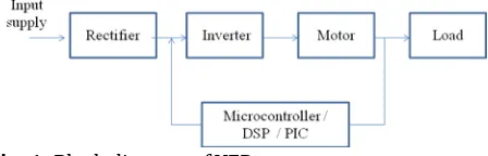
It is one of the popular controller topology used in various industries for its starting , flexibility in speed control and operation performance in induction motor . Previously, it was not that much popular because of its complex contruction and high cost. Since last four decades after the invention of power electronic devices such as SCR , MOSFET , etc. The cost get reduced , less size , simple construction has improved the performance of Variable Frequency Drives. The Block diagram of VFD is shown in fig.(1)
Fig -1: Block diagram of VFD
In starting a motor, VFD applies low frequency and voltage thus avoids high inrush current and also reduces voltage sag. With VFD , Starting current is about 1.5 times the full load current which is quiet less as compared to direct starting. It can also act as a starter along with Direct on Line method for induction motor.
Now, The speed of induction motor mainly depends on the frequency and number of poles which can be represented as
(1)
p f rpm
[image:1.595.314.538.546.618.2]© 2016, IRJET | Impact Factor value: 4.45 | ISO 9001:2008 Certified Journal
| Page 1684
Where,
N = Speed of the Motor (rpm) f = Frequency (Hz)
P – Number of poles
2.2 Methodology
Fig.(2) shows the equivalent circuit of Variable Frequency Drive. We can see that ac supply lines is given to the power input and then its output is fed to the motor. The basic function is to act as a variable frequency generator to vary speed as per load requirement [3].It can vary the required speed by simply changing the frequency using switching sequence of power electronic devices. Now a days, for switching purpose IGBT are used. For getting low cost, high efficiency, high performance speed control circuit is design.
V
Induction Motor
AC AC
AC V
V D1
D2 D3
D4 D5
D6
T5 T3 T1
T4 T6 T2
+
-C Vdc
S
Ia Ib
Ic
Fig -2: Equivalent circuit of Variable Frequency Drive It consist of following stages of operations which are as follows:
2.2.1 Rectifier Stage
It converts Single or three phase ac input supply to fixed dc voltage. Rectifier used here is 3 phase full wave diode bridge rectifier which consist of 6 diodes connected as shown in fig.(3) It includes transformer of high voltage system.
D1
D2 D3
D4
D5
D6 Ia
Ib
Ic
VaAC Vb Vc
AC AC
Fig -3: 3-Phase Bridge Rectifier
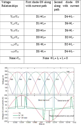
[image:2.595.303.565.204.610.2]During first cycle , positive current flows through diode D1 and then through D4. Remaining cycles are shown in Table 1 , with corresponding phase and direction of current. Vab and Vbc are the peak voltage for positive current , Vba and Vca for negative current as shown in fig.4.
Table -1: Diode And Current Flow In 3-Phase Rectifier Voltage
Relationships
First diode ON along with current path
Second diode ON along with current path
Vab>Vdc D1Ia+ D4Ib -
Vac>Vdc D1Ia+ D6Ic -
Vbc>Vdc D3Ib+ D6Ic -
Vba>Vdc D3Ib+ D2Ia-
Vca>Vdc D5Ic+ D2Ia -
Vcb>Vdc D5Ic+ D4Ib -
None>Vdc None Ia = Ib = Ic = 0
Fig-4: Output Current and Voltage waveform of 3-phase rectifier
2.2.2 DC Link Bus
[image:2.595.37.277.311.428.2] [image:2.595.49.225.586.741.2]© 2016, IRJET | Impact Factor value: 4.45 | ISO 9001:2008 Certified Journal
| Page 1685
3-Phase AC [image:3.595.42.272.101.162.2]Supply Motor
Fig -5: DC link bus
2.2.3 Inverter Stage
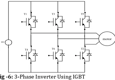
It converts fix or variable dc voltage to variable ac voltage. Fig.(6) shows three phase inverter having IGBT as the switching device. Now a days, IGBT is a common choice for the selection of switching device for VFD. As it can switch ON and OFF several thousand times per seconds and control the power deliver to the induction motor.
DC
-T1 T3 T5
T4 T6 T2
[image:3.595.314.546.275.364.2]motor
Fig -6:3-Phase Inverter Using IGBT
[image:3.595.42.239.299.436.2]To generate the sine wave pulses or in other words , to give triggering to the switches. IGBT uses pulse width modulation technique at desired frequency. It is also called as PWM Inverter. The possible switching states of IGBT at different cycle is shown in Table 2 below.
Table -2: Switching States Of 3-Phase Inverter State State No. Switching States
Sa Sb Sc
T1, T2, T6 are on 1 1 0 0
T1, T2, T6 are on 2 1 1 0
T3, T4, T2 are on 3 0 1 0
T4, T5, T3 are on 4 0 1 1
T5, T6, T4 are on 5 0 0 1
T6, T1, T5 are on 6 1 0 1
T1, T3, T5 are on 7 1 1 1
T4, T6, T2 are on 0 0 0 0
It is the process which characterizes the variation in the width of the pulses is directly proportional to small control signals. The width for the pulses changes according to the voltage control signal as the control signal changes the wider the simulation of the pulses produce. By using sinusoid of desired frequency in pwm control signal, we can generate high power waveform which helps the ac motor to run in sinusoidal manner.
In this method, fixed gate signal has given to IGBT switch from pulse generator, then switch will operate . In PWM technique, user can change the duty cycle by simply changing the frequency and amplitude modulation.
Carrier Wave
Reference Wave
Comparator
Generated PWM signals
Fig -7:Block Diagram of PWM
Fig.(7) shows basic working of PWM. Here , two signals i.e. Carrier signal and Reference signal are compared together with comparator ( Relational operator in MATLAB). It compares both the waveforms and gives output as per requirement. This is also called as Modulation Index which is given as
c r
A
A
I
M
.
.
Where,
Ar = Amplitude of Reference Signal. Ac= Amplitude of Carrier Signal.
For example, as shown in fig.(8) consider reference signal is fixed DC while Triangle wave is carrier signal [7]. Now the condition <= (relational operator) is applied if the reference signal is less than the carrier signal means also fixed DC is less than Triangle wave then we will get output otherwise the output will be zero (0). By changing modulation index, we can vary the output directly. It will consider one reference signal & other as carrier signal.
<=
Vdc
Vtri
Vout
t
m Fixed DC
Triangular Wave
Reference Time Clock
Output Waveform
Combined Waveform Relational Operator
Fig -8:Simulation of PWM control signals
[image:3.595.35.554.512.796.2]© 2016, IRJET | Impact Factor value: 4.45 | ISO 9001:2008 Certified Journal
| Page 1686
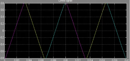
Fig -9:Waveform of reference signal and carrier signal As shown in fig 8-9 , in order to generate 6 pulses for triggering, sinusoidal reference wave is compared with high frequency carrier triangular wave. The three sine waves are delayed for 120 degree from each other. [4] As induction motor are widely used in many industries , PWM based inverter provide better result for the v/f control. Amongst various PWM technique sinusoidal pwm techniques is extensively used and most popular because of its smooth v/f control , harmonic elimination and four quadrant operation.
4. HARDWARE DESCRIPTION
[image:4.595.45.252.96.251.2]The hardware for the variable frequency drive control , power circuit is designed .
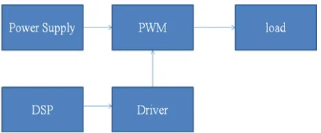
Fig -10:Block diagram for Hardware Driver Circuit
Fig.(10) shows proposed block diagram of driver circuit in hardware implimentations. Driver circuit consist of inverter. From fig. 1 , we can see that controller circuit receives a information as a feedback from the driven motor and adjusts the output voltage or frequency as per load requirement. The controller generates PWM signal to the converter[4]. Various controller such as DSP , PIC and microcontrollers are used. Now a days , DSP [5] are mostly preferred over microcontroller and PIC as it offers higher speed, higher resolution. The hardware model of VFD based Induction Motor shown in fig.(11)
Fig -11:Hardware Model of Variable Frequency Drive
5. SIMULATION ANNALYSIS AND ITS EXPERMENTAL
RESULTS
[image:4.595.309.558.381.483.2]Results for SPWM inverter for resistive load connected is shown (fig.12-18) using MATLAB and PSIM. A constant 400 v dc supply is given to the inverter circuit. For triggering of the switches, SPWM is taken with modulation index less one. Line voltage, phase voltage and output voltage are measured and compared for both with filter and without filter.
Fig -12:Waveform of line Voltage of 3-phase SPWM inverter without filter
[image:4.595.36.269.471.568.2] [image:4.595.310.558.522.628.2]© 2016, IRJET | Impact Factor value: 4.45 | ISO 9001:2008 Certified Journal
| Page 1687
Fig -14: Waveform of Output Voltage of 3-phase SPWM inverter with filter
Fig -15: Waveform of control signal of 3-phase SPWM inverter
Fig -16: Simulation of VFD based induction motor drive using PSIM.
[image:5.595.305.543.76.221.2]Fig -16:Starting Current
Fig -18:Speed
[image:5.595.37.284.104.208.2]For experimental research on control scheme, Induction motor is used (Table 3). During the operation of hardware model shown in fig.(9) , proximity sensor is connected between motor and VFD to sense speed of the motor. In order to display speed and frequency, we use digital meter. Analog meter for voltage and current of motor. The results which have been noted is shown below (Table 4).
Table -3: Induction Motor Specifications
Number of poles 4
Phase 3
Rated Power 0.75KW
Rated Voltage 415 V (Star)
Rated Current 1.8 A
Supply Frequency 50Hz
Rated Speed : 1395 rpm
Power Factor 0.81
Table -4: Expermental Results Of VFD Based Induction Motor
Voltage (V) Frequency (HZ) Speed (RPM)
195 46.34 1392
170 40.12 1206
160 38.83 1168
130 33.33 1000
110 29.30 897.4
[image:5.595.37.287.250.368.2] [image:5.595.302.566.349.543.2] [image:5.595.36.269.413.550.2]© 2016, IRJET | Impact Factor value: 4.45 | ISO 9001:2008 Certified Journal
| Page 1688
6. CONCLUSIONS
This paper has introduced about variable frequency drive in induction motor. With the help of variable frequency drive , starting current and speed control can be efficient by varying supply voltage and frequency . For analysis purpose, SPWM control is used. As variable Frequency Drive (VFD) to a motor driven system , it can offer energy saving in a system in which the load vary with time. It also provides less distortion, lower switching frequencies and high efficiency. The experimental results is also presented which shows that it has good performance , rapid dynamic response and has wide range of applications in various fields. Thus variable frequency drive starting and speed control has been investigated in this paper.
REFERENCES
[1] Puja Talukder, Prashant Kumar Soori, and Benetta Aranjo, “ Speed Control of Induction Motor Drive Using Universal Controller” IEEE International Power Engineering and Optimization Conference (PEOCO2012), Melaka, Malaysia: 6-7 June 2012 [2] Chandan Chakraborty , “Speed and Current Sensor Fault
Detection and Isolation Technique for Induction Motor Drive Using Axes Transformation” IEEE TRANSACTIONS ON INDUSTRIAL ELECTRONICS, VOL. 62, NO. 3, MARCH 2015.
[3] Leon Max Vargas, Student Member, IEEE, Juri Jatskevich, Senior Member, IEEE, and Jose R. Martí, Fellow, IEEE, “Load Modeling of an Induction Motor Operated with a Variable Frequency Drive,” 2008 IEEE Electrical Power & Energy Conference.
[4] H Brandstetter, P Kusun, “Induction motor drive with DSP-based control system ” Industrial Electronics ,Proceeding of the IEEE International Symposium 1996. [5] Frank Chen1, Lin Wang2, Chenglin Gu3, Helen Cheung4, Ivan Lee5, Richard Cheung6, “ Real-Time DSP-Based Computation-Efficient Speed-Sensorless Drive of Induction Motors ” 2008 International Conference on Electrical Machines & Systems ICEMS 2008.
[6] Xiaodong Liang, Member IEEE , Ryan Laughy Member IEEE Joe Liu, Member, IEEE ,” Investigation of Induction Motors Starting and Operation with Variable Frequency Drives” CCECE 2007