ISSN: 1992-8645 www.jatit.org E-ISSN: 1817-3195
235
ASSEMBLY SEQUENCE PLANNING METHOD FOR
COMPLIANT ASSEMBLY
1LIHONG QIAO, 2NA CAI
Advanced Manufacturing Technology and Systems Research Center, Department of Industrial and
Manufacturing Systems Engineering, Beihang University, 37 Xueyuan Road, Beijing 100191, China
E-mail: [email protected], [email protected]
ABSTRACT
Compliant assemblies are widely used in automobiles and airplanes etc. In order to simplify the complex assembly sequence planning problem of compliant assemblies involving dimensional variation caused by deformation, a two-step assembly sequence planning method is proposed in this paper. Meanwhile, an example of a wingbox assembly is used to explain the principle of the method. In the first step the wingbox is assumed to be a rigid body without deformation. The assembly sequence is then acquired according to the precedence constraint relationships represented by the liaison graph and the adjacency matrix. On the basis of the result obtained in the first step, the assembly sequence which meets the dimensional quality requirements is acquired by dimensional variation analysis in the second step. In order to clearly express the precedence and hierarchical constraint relationships for large number of parts, the hierarchical liaison graph based on connection feature is proposed and applied on modeling the wingbox assembly.
Keywords: Assembly Sequence Planning (ASP), Compliant Assembly (CA), Wingbox
1. INTRODUCTION
Assembly sequence planning (ASP) is a critical technology that is identifying and evaluating the
different sequences in which parts and
subassemblies are put together automatically based on assembly modeling. ASP is quite significant for assembly process since a good assembly sequence can dramatically improve the efficiency, cost as well as quality. Intensive studies have been focused on ASP since 1984 when Bourjault [1] proposed the first ASP approach based on functional liaison graphs and precedence constraints between the liaisons. In 1990, Homem de Mello and Sanderson [2] proposed an AND/OR graph approach for the representation of assembly plans and an algorithm to generate assembly sequences. Over the decades, research work of ASP has been explored intensively in optimization algorithms like genetic algorithms [3] and knowledge-based engineering [4], etc.
Most of the ASP research works are aimed at rigid body assemblies without consideration of the deformation during the assembly process. However,
compliant assemblies are widely used in
automobiles and airplanes etc [5]. The components of compliant assemblies are deformable and the dimensional variation caused by deformation propagates during the assembly process [6], which
makes the assembly process much more complex. In order to solve the problem, a two-step assembly sequence planning method for compliant assembly is proposed in this paper, and an example of a wingbox assembly is used to explain the principle of the method.
The liaison graph has been widely used in modeling the assembly process because it describes the precedence relationships between parts very well. However, for large number of parts, the constraint relationships are too complicate to be described in the liaison graph. Meanwhile, assembly hierarchical information and assembly connection information is not contained in the liaison graph. In order to solve the problem, the hierarchical liaison graph based on connection feature is proposed and also applied to model the wingbox assembly in this paper.
2. TWO-STEP ASSEMBLY SEQUENCE
PLANNING METHOD OF COMPLIANT ASSEMBLY
ISSN: 1992-8645 www.jatit.org E-ISSN: 1817-3195
236 should be taken seriously. Take a wingbox for example, a wingbox is made up of four main components: the ribs, the longitudinal spars, the skins and the stringers [7]. The wingbox is built in the assembly jigs where all the components are loaded in a specific sequence. And it has been observed that a completed wing that has come out of the assembly jig was twisted due to change in the structure shape during assembly [8].
The dimensional variation propagates during the assembly process so assembly sequence has notable impact on the final dimensional quality of the wingbox assembly. Therefore, ASP for compliant assembly like wingbox is a complicated problem. In order to simplify the process, a two-step assembly sequence planning method of compliant assembly is proposed. The first step is assembly sequence planning of wingbox as a rigid body based on precedence constraint relationship between components. In this step the assembly sequence which meets the geometrical constraint requirements can be acquired. The second step is assembly sequence planning of wingbox as a compliant body based on dimensional variation analysis. In this step, the assembly sequence which meets the dimensional quality requirements can be acquired on the basis of the result obtained in the first step.
In order to explain the method, an example of a wingbox with nine ribs, two skins (top skin and bottom skin), two spars(front spar and rear spar), ten strings(five for each skin) is used to explain the principle of the proposed assembly sequence planning method. However, the developed method can be generalized into other assembly process with compliant parts
2.1 Step1: Assembly Sequence Planning of Wingbox As Rigid Body
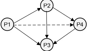
In the first step the wingbox is assumed to be rigid body so there is no deformation during the whole assembly process. Under this assumption, the assembly sequence of different ribs has no impact on the final assembly quality and they are in the same geometrical precedence constraint, so all the ribs can be considered as one part. Similarly, all the stringers, spars and skins can be considered as one part, respectively. Therefore, a wingbox with many parts is simplified as assembly of four parts: spar(P1), rib(P2), skin(P3), stringer(P4). The liaison graph of wingbox assembly as rigid body is shown in Figure 1. The line with arrow represents physical connection with precedence constraint while the dash line with arrow represents dummy connection (dummy connection means no physical contact
between parts) with precedence constraint. The constraints can be expressed through the adjacency matrix: R=[rij]4×4.
Figure 1. Liaison graph of wingbox assembly as rigid body
P1 P2
P3
P4
P1
0
1
1
P2
1
0
1
1
R
P3
1
1 0
1
P4
1 1
0
λ
λ
−
=
−
−
−
−
−
(1)In the adjacency matrix R, rij =1 represents
physical connection and part i is assembled before
part j; rij =
−
1
represents physical connection andpart i is assembled after part j; rij =
λ
representsdummy connection and part i is assembled before
part j; rij =
−
λ
represents dummy connection andpart i is assembled after part j; rij =0 represents
there is no precedence constraint between part i and part j [9].
In [10], three subassembly patterns which are serial, parallel and loop relations were defined and the method of identifying the three subassembly patterns by adjacency matrix was also given.
Therefore, by applying the method, the
subassembly patterns of wingbox can be identified by adjacency matrix R. Define every subassembly in an assembly sequence is an assembly unit, short for AU. Two assembly sequences can be obtained as followed:
Assembly sequence 1: {{Serial AU: P1, P2, P4}, P3}
Assembly sequence 2: {{ Serial AU: P1,P2}, {Serial AU: P4,P3}}
[image:2.612.354.497.139.223.2]ISSN: 1992-8645 www.jatit.org E-ISSN: 1817-3195
237
2.2 Hierarchical Liaison Graph Based On Connection Feature
The liaison graph describes the precedence relationships between parts very well, but when the number of parts is large the precedence relationships are too complicate to be described in the liaison graph. Meanwhile, assembly hierarchical information and assembly connection information is not included in the liaison graph. In order to solve the problem, the hierarchical liaison graph based on connection feature is proposed in this paper.
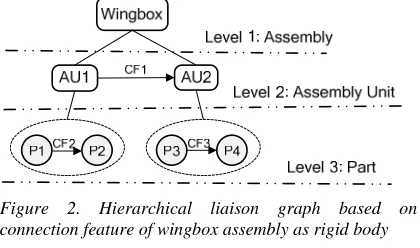
The hierarchical liaison graph based on connection feature of wingbox assembly as rigid body is shown in Figure 2. The graph is divided into three hierarchies: assembly level, assembly unit level and part level. The graph can be described by a set with 4 elements{AU, P, R, CF}, in which AU represents assembly unit, R represents precedence relationships between parts or assembly units described by the adjacency matrix and CF represents connection feature between parts or assembly units. The connection feature CF={CP, CT, CN} where CP is connecting parts, CT is connection type and CN is connection number.
In Figure 2, the line without arrow represents the
parent-child relationship between different
hierarchies. The line with arrow represents physical connection with precedence constraint between parts. In the assembly unit level, AU1 is the wing structure that is serial assembly unit of P1 and P2, AU2 is the wing panel that is serial assembly unit of P3 and P4. Fig.2 can be described by the set with 4 elements{AU, P, R, CF}, in which:
AU={AU1, AU2}. (2)
Where: AU1={P1,P2,CF2}, AU2={P3,P4,CF3}.
P={P1, P2, P3, P4}. (3)
R={R1, R2, R3}. (4)
Where:
AU1 AU2
AU1 0
1
R1
AU2
1 0
=
−
,P1 P2
P1 0
1
R2
P2
1 0
=
−
,P3
P4
P3 0
1
R3
P4
1 0
=
−
.CF={CF1, CF2, CF3}. (5)
Finally, the assembly sequence of wingbox assembly as rigid body can be described as {{AU1: P1,P2,CF2},{AU2: P3,P4,CF3},CF1}.
Figure 2. Hierarchical liaison graph based on connection feature of wingbox assembly as rigid body
2.3 Step2: Assembly Sequence Planning Of Wingbox As Compliant Body
The assembly sequence {{AU1:
P1,P2,CF2},{AU2: P3,P4,CF3},CF1} meets the geometric precedence constraint requirements, but it is acquired under the assumption that the wingbox is rigid body without deformation so that all the skins, stringers, ribs and spars can be considered as single part respectively. However, all the components of the wingbox are compliant and deformable and the dimensional variation caused by deformation can propagate during the assembly process, so in order to assure the final dimensional quality of the wing box the assembly sequence of every real part should be planned on the basis of the assembly sequence obtained in the first step. In this case, front spar(P1a) and rear spar(P1b), nine ribs(P2a-P2i), top skin(P3), bottom skin(P5), five stringers(P4a-P4e) attached to top skin and five stringers(P6a-P6e) attached to bottom skin should
be considered as single part respectively.
Dimensional variation for different assembly sequence between parts can be calculated by FEM so that the assembly sequence with optimal dimension quality can be acquired.
[image:3.612.317.527.212.336.2]ISSN: 1992-8645 www.jatit.org E-ISSN: 1817-3195
238 assembly sequence of front spar and rear spar will affect the final dimensional quality of the wingbox assembly.
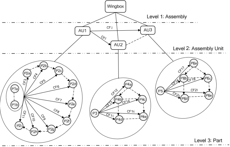
Figure 3 is the hierarchical liaison graph based on connection feature of wingbox assembly as compliant body. In the graph, the dash line with
arrow represents dummy connection and the parts connected by the dash line with arrow are assembled in precedence constraint. Moreover, the dash line without arrow represents dummy connection as well but the parts connected by the dash line without arrow are assembled to the same part simultaneously.
CF
4
C
F
9
CF 12
CF 13
[image:4.612.129.497.192.427.2]CF 17
Figure 3. Hierarchical Liaison Graph Based On Connection Feature Of Wingbox Assembly As Compliant Body.
In the assembly unit level, AU1 is still the wing structure consisted of front spar, rear spar and nine ribs, but the wing panel is divided into top wing panel(AU2) and bottom wing panel(AU3), and both of them are consisted of one skin and five ribs. AU2 and AU3 are assembled simultaneously [11]. In the part level, P1a and P1b represent front spar and rear spar respectively and they’re also assembled simultaneously. P2a to P2i are the nine ribs assembled to the spars, and the dash lines with arrow shows the assembly sequences between the different ribs. P3 is the top skin and P4a to P4e are the five stringers assembled to the top skin P3. P5 is the bottom skin and P6a to P6e are the five stringers assembled to the bottom skin P5. Figure 3 can be described by the set with 4 elements{AU, P, R, CF}, and the assembly sequence of wingbox assembly as compliant body can be described as: {{{AU1:{{{{{{{{{P1a,P1b},P2a,CF3},P2b,CF4},
P2c,CF5},P2d,CF6},P2e,CF7},P2f,CF8},P2g,CF9} ,P2h,CF10},P2i,CF11},{AU2:{{{{P3,P4a,CF12},P 4b,CF13},P4c,CF14},P4d,CF15},P4e,CF16},CF1}, {AU3:{{{{P5,P6a,CF17},P6b,CF18},P6c,CF19},P 6d,CF20},P6e,CF21},CF2}.
3. SUMMARY
Assembly sequence planning of a wingbox example which is a compliant assembly has been realized in two steps. In the first step, wingbox is assumed to be a rigid body and the assembly sequence is then acquired according to the precedence constraint relationships represented by the liaison graph and the adjacency matrix. The second step is assembly sequence planning of wingbox as a compliant body based on dimensional variation analysis and the hierarchical liaison graph
based on connection
feature is applied on modeling the wingbox assembly process.
It can be concluded that with the proposed two-step assembly sequence planning method for
ISSN: 1992-8645 www.jatit.org E-ISSN: 1817-3195
239 based on connection feature is quite applicable on modeling the assembly process, especially for assembly of large number of parts. It contains
abundant assembly information including
precedence constraint relationships between parts,
hierarchical information and connection
information.
ACKNOWLEDGEMENTS
This work is partially supported by the National Natural Science Foundation of China (Grant 51075022). The authors would also like to thank the support from Beijing Municipal Education Commission (Build a Project).
REFRENCES:
[1] Bourjault A, Contribution to a Mythological approach of automated assembly: automatic generation of assembly sequence [Ph. D. Thesis]. University of Franche-Comte, Beacon, France, 1984.
[2] Luiz S. Homem de Mello, Arthur C. Sanderson, A correct and complete algorithm for the generation of mechanical assembly sequences,
IEEE Transactions on Robotics and
Automation. 7 (1991) 228-240.
[3] Wei Zhou, Jian-rong Zheng, Jian-jun Yan, Jun-feng Wang, A novel hybrid algorithm for
assembly sequence planning combining
bacterial chemotaxis with genetic algorithm. Int J Adv Manuf Technol. 52 (2011) 715–724. [4] Dong T, Tong R, Zhang L, Dong J, A
knowledge-based approach to assembly
sequence planning. Int J Adv Manuf Technol. 32 (2007) 1232–1244.
[5] Hui Chenga, Yuan Li, Kai-fu Zhang, Wei-qiang Mu, Bo-feng Liu, Variation modeling of aeronautical thin-walled structures with multi-state riveting, Journal of Manufacturing Systems. 30 (2011) 101-115.
[6] Jaime Camelio, S. Jack Hu, Dariusz Ceglarek, Modeling variation propagation of multi-station assembly systems with compliant parts, Journal of Mechanical Design. 125 (2003) 673-681. [7] M. Saadat, R. Sim, F. Najafi, Modelling and
analysis of airbus wingbox assembly, Proc. IMechE. 222 (2008) 701-709.
[8] Mozafar Saadat, Roy Sim, Farid Najafi, Prediction of geometrical variations in airbus wingbox assembly, Assembly Automation. 27 (2007) 324-332.
[9] Zhang Yizhu, Zhou Jiangqi, Lin Zhongqin, Ni
Jun, Automatic process planning and
subassembly detection for auto-body assembly, Journal of Computer-aided Design & Computer Graphics. 15 (2003) 680-684.
[10] Y. Xing, G. Chen, X. Lai, S. Jin and J. Zhou. Assembly sequence planning of automobile body components based on liaison graph. Assembly Automation. 27 (2007) 157-164 [11] Brian Rooks, Automatic wing box assembly
developments, Industrial Robot: An