ISSN: 1992-8645 www.jatit.org E-ISSN: 1817-3195
A NOVEL POWER EFFICIENT ON-CHIP TEST GENERATION
SCHEME FOR CORE BASED SYSTEM-ON-CHIP (SOC)
B. SAGAR,S. RAJENDAR, R. MURALI PRASAD
Department of Electronics and Communication Engineering,
Vardhaman College of Engineering (Autonomous), Hyderabad, Telangana, India
E-mail: [email protected], [email protected], [email protected]
ABSTRACT
In this paper, a modified programmable twisted ring counter (MPTRC) based on-chip test generation scheme is proposed. It is used as built-in-self-test (BIST) pattern generator for high performance circuits with simple test control. This method is used to achieve low power and reduced test time for digital circuits. The MPTRC module is designed with Cadence NClaunch platform using Verilog HDL and synthesis done by using Cadence RTL compiler with 0.18µm technology. The simulation results show about 13.46% power reduction compared with conventional programmable twisted ring counter (PTRC) based design.
Keywords: Built-in-self-test (BIST), System-on-chip (SoC), Ring counter, Twisted-ring-counter (TRC), Programmable twisted ring counter (PTRC).
1. INTRODUCTION
[image:1.612.119.283.546.648.2]VLSI technology includes two testing processes as test generation and test application [1]. The goal of test generation is to produce test patterns for efficient testing. Test application is used to apply test patterns to the circuit-under-test (CUT) and analyze their output response. Test application is performed either by automatic test equipment (ATE) or test facilities in the chip itself. Conventional testing methods based on automatic test equipment (ATE) are not suitable for system-on-chip (SoC) as it requires large test time, test data volume and increase the total test cost of the circuit.
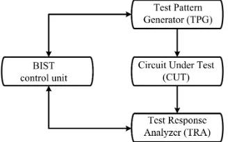
Fig 1: General Structure Of Built-In-Self-Test (BIST)
Built-In-Self-Test (BIST) is a design for testability (DFT) technique used for self-testing [2], [6]. It is an effective technique used for testing system-on-chip (SoC) as it reduces the test time, test data volume and decreases the test cost of the
circuit. The main components of the BIST scheme are illustrated in Fig 1. The test pattern generator is used for generating the test pattern for circuit-under-test (CUT). Test response analysis is used to compare and analyze the response.
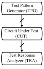
[image:1.612.313.524.589.676.2]Generally BIST methods are categorized into clock and scan [2]-[3]. In test-per-clock method, a test pattern is applied to the CUT for clock cycle and test response is captured by response monitor. In test-per-scan method, a test pattern is serially loaded into scan chains bit-by-bit. Therefore it requires large test time on loading pattern when the scan chain length is high. The advantage of test-per-clock method is that it requires short test time on one test pattern compared with test-per-scan method. Therefore test-per-clock is good choice for testing.
Fig 2: Test-Per-Scan
ISSN: 1992-8645 www.jatit.org E-ISSN: 1817-3195 test time to control hard-to-detect-faults known as
[image:2.612.163.237.137.254.2]random pattern resistant (r.p.r) to get satisfactory fault coverage.
Fig 3: Test-Per-Clock
Deterministic circular self-test path (DCSTP) and mixed mode are also test-per-clock methods [4]. DCSTP technique is applying a set of test patterns with unspecified bits to the circuit-under-test (CUT) and a special BIST cell is placed instead of each IO pins and internal flip-flops to connect these cells together to form a long circular self-test path. In this scheme, large jumping logic or long test time is required to generate required test patterns for 100% fault coverage. Mixed mode method is to combine the pseudo random testing schemes with various deterministic circular self-test schemes (DCSTP). Pseudo random test patterns in mixed mode scheme are used to detect the easy-to-detect faults and deterministic patternsare used to detect hard-to-detect faults. An additional logic is required to control the test process between different test modes. These methods require long test time to reach satisfactory fault coverage.
[image:2.612.99.300.591.722.2]Other test-per-clock methods are based on twisted-ring-counters (TRCs) and reseeding logic which covers maximum faults [5], [9]. A twisted ring counter also called as Johnson counter is a modified ring counter, where the inverted output from the last flip flop is connected to the input of the first flip flop as shown in fig 5.
Fig 4: Ring Counter
Fig 5: Twisted-Ring-Counter (TRC)
Fig 6: Configurable Ring Counter
By using TRC technique, unique seed can be found easily. TRC can be used as single twisted-ring-counter or programmable twisted twisted-ring-counter (PTRC). PTRC is fast in generating test patterns compared with single twisted-ring-counter. TRC based test-per-clock method has following advantages 1) simple test control, 2) controllability and 3) no additional logic is added on critical paths of the CUT, hence performance impact is small. With these advantages TRC based BIST methods are more efficient to promising low test solution for high performance circuits.
In this paper, twisted ring counters (TRCs) are used as BIST pattern generator. A modified programmable twisted ring counter (MPTRC) is proposed to generate more different test patterns for testing with short time and low power. This technique is more efficient than the pseudo random testing method to control random-pattern-resistant faults (r.p.r) and there is no need of an additional logic to generate test patterns for high fault coverage.
This paper is organized as follows. Section II reviews the conventional twisted-ring-counter (PTRC) based test generation. Section III discusses the proposed modified programmable twisted-ring-counter (MPTRC) and section IV shows simulation results. Finally, section V concludes this work.
2. PREVIOUS METHOD
Fig. 7 shows the programmable multiple twisted-ring-counters (PTRC) scheme with some reseeding logic, which generates the required test patterns for testing. In this scheme, according to the circuit-under-test (CUT) scan registers are split into multiple equal scan segments and each scan segment is converted into programmable TRCs with reversion logic unit.
ISSN: 1992-8645 www.jatit.org E-ISSN: 1817-3195 from ROM. The PTRC design is based on
configurable ring counter as shown in Fig. 6, is a combination of ring counter (RC) and twisted-ring-counter (TRC). A ctrl is a control signal, which acts as a switch between ring counter (RC) and twisted-ring- counter (TRC) modes. It can generate the maximum 3m different patterns for testing. By using this scheme, both test application time and storage data volume can be significantly reduced.
[image:3.612.92.299.208.392.2]
Fig 7: Programmable Twisted-Ring-Counter (PTRC) with Two Scan Segments
The test generation process of PTRC is controlled by centralized mode switching logic unit and reversion logic units. Under the control of these units, PTRC units jointly generate the required patterns for testing and at the same time reduce the test application time. By adjusting the control signal of each reversion logic unit, it is used to perform different test generation modes, which generates more effective test patterns for testing and significantly reduces the total storage data volume.
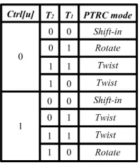
Fig 8: Control Signals for Different PTRC Modes
The PTRC design presents three test generation modes called shift-in, rotate and twist. The shift-in mode is used to load the seed into the PTRCs. Each
seed is scanned in from external tester or stored in an on-chip ROM. The rotate mode circularly shifts the seed by one bit per test cycle. The twist mode also performs shift operation on the seed circularly, which additionally flips the last bit of the logical value to the first bit. Based on a seed pattern, various test patterns can be generated by switching between rotate and twist modes. A control signal denoted as ctrl is presented to control the reversion logic unit in PTRC units. Two possible 3m test patterns are generated for each seed by adjusting the control signal (ctrl). When ctrl[0] = 1, the test pattern order is shift-in twist twist rotate, while when ctrl[1] = 0, the test pattern order is shift-in rotate twist twist.
3. PROPOSED METHOD
[image:3.612.316.519.428.602.2]The proposed design modified programmable twisted-ring-counter (MPTRC) is shown in Fig. 9, where AND gates are replaced with NAND gates and XOR gates are replaced with XNOR gates. Compared with AND gate and XOR gate high performance can be achieved with NAND and XNOR gates. By using inverters to NAND and XNOR gates AND, XOR gates are realized. Using these NAND and XNOR gates number of stages, delay and power can be reduced.
Fig 9: Modified Programmable Twisted-Ring-Counter (MPTRC) with Two Scan Segments
In mode switching logic unit (MSL), 2-bit binary counter (bc) is replaced with 2-bit twisted-ring-counter (TRC), where delay and power can be reduced when compared with binary counter. Mode of operation for 2-bit TRC in test generation circuit is denoted by T counter and is enabled by k-bit
[image:3.612.154.251.561.674.2]ISSN: 1992-8645 www.jatit.org E-ISSN: 1817-3195 keeps a track of how many cycles have been
executed in PTRC unit.
In this proposed design, centralized mode switching logic unit in the test generation circuit counts the number of clock cycles for each pattern generation. These clock cycles counted by the variable is given as k and is defined by k =
log
2m
, where m is length of the shift register or length of scan segments. The clock cycles are counted by thek-bit binary counter. The enabling of T counter
[image:4.612.144.246.293.413.2]between 2-bit TRC counter and k-bit binary counter is done by using AND gate. In modified PTRC, 2-bit TRC is initially loaded with 00 that generates the four states 00, 01, 11 and 10. This is incremented only by k-bit binary counter (Kbc).
Fig 10: Control Signals for Different MPTRC Modes
Reversion logic units are developed with NAND gates that take control of various TRC operations to generate the required test patterns based on the seeds. A control signal denoted as ctrl is presented to control the reversion logic unit in PTRC units. Two possible 3m test patterns are generated for each seed by adjusting the control signal (ctrl).
When ctrl[0] = 1, the test pattern order is shift-in twist twist rotate, while ctrl[1] = 0, the test pattern order is shift-in rotate twist twist. By adjusting the control signal of each reversion logic unit, it is used to perform different test generation modes that generates more effective test patterns for testing and significantly reduces the total storage data volume.
4. RESULTS AND ANALYSIS
Modified programmable twisted ring counter generates the test patterns under fault condition to test the circuit. Mode switching logic unit and reversion logic are two main important blocks in test generation circuit for change of mode and generating different combination of patterns. Control input with 0 or 1, reversion logic unit is performed and mode switching logic unit is to
stabilize the mode for certain clock cycles. The test patterns are generated from test generation circuit can be used for detecting the faults.
The experiments results of conventional programmable twisted-ring-counter (PTRC) and modified programmable twisted-ring-counter (MPTRC) designs are implemented by Cadence Nclaunch platform using Verilog HDL and synthesis is done by using Cadence RTL compiler with 0.18µm technology.
Table I and table II summarizes some important performance metrics of the programmable twisted ring counter (PTRC) and modified programmable twisted ring counter (MPTRC) and table III shows the power comparisons between PTRC and MPTRC. These include leakage power, dynamic power and total power.
Table 1: Power consumption of cells used in Conventional PTRC.
Instance Cells
Leakage Power (nw) Dynamic Power (µw) Total Power (µw)
PTRC 44 47.01 27.49 27.54
MSL Kbc Bc 14 7 5 13.05 6.81 4.59 6.89 3.24 2.77 6.90 3.25 2.72
PTRC unit 1 Shift register MUX 8 5 1 9.16 5.78 1.31 6.16 3.11 5.79 5.93 3.15 5.80
[image:4.612.317.519.548.720.2]PTRC unit 2 Shift register MUX 8 5 1 9.16 5.78 1.31 5.92 3.14 5.79 5.93 3.15 5.80 LFSR 1 LFSR 2 6 6 7.26 7.06 3.06 3.41 3.07 3.41
Table 2: Power consumption of cells used in Modified PTRC.
Instance Cells
Leakage Power (nw) Dynamic Power (µw) Total Power (µw)
MPTRC 43 43.71 23.85 23.89
MSL Kbc TRC 13 7 4 12.06 6.82 3.60 4.67 3.24 4.99 4.69 3.25 5.03
PTRC unit 1 Shift register MUX 8 5 1 8.40 5.78 1.31 5.36 3.11 4.50 5.37 3.12 4.51 PTRC unit 2
ISSN: 1992-8645 www.jatit.org E-ISSN: 1817-3195
Table 3: Power comparisons between PTRC and MPTRC based design.
Instance name PTRC MPTRC
Leakage Power (nw) 47.01 43.71
Dynamic Power (µw) 27.49 23.85
Total Power (µw) 27.54 23.89
5. CONCLUSIONS
In this paper, a modified programmable twisted ring counter (MPTRC) scheme is proposed. It is used as built-in-self-test (BIST) pattern generator for high performance circuits with simple test control. Simulation results show that the proposed MPTRC power is reduced by 13.46% compared with conventional programmable twisted ring counter (PTRC). The future work is to implement an efficient algorithm on FPGA devices to minimize the length of test sequence to achieve high fault coverage for high performance applications.
REFRENCES:
[1] Cheng-Wen Wu, Laung-Terng Wang, Xiaoqing Wen, “VLSI Test Principles and
Architectures: Design for Testability”. San
Mateo, CA, USA: Morgan Kaufmann, 2006. [2] Dhiraj K. Pradhan and Chunsheng Liu,
Member, IEEE, EBIST: “A Novel Test Generator with Built-In Fault Detection Capability”, IEEE Transactions On Computer-Aided Design Of Integrated Circuits and Systems, vol. 24, no. 9, september 2005. [3] Kuen-Jong Lee, Wei-Cheng Lien, Tong-Yu
Hsieh and Wee-Lung Ang, “An Efficient On-Chip Test Generation Scheme Based on Programmable and Multiple Twisted-Ring Counters”. IEEE transactions on computer-aided design of integrated circuits and systems, vol. 32, no. 8, august 2013.
[4] Krishnendu Chakrabarty, Brian T. Murray, and Vikram Iyengar, “Deterministic Built-In Test Pattern Generation for High-Performance Circuits Using Twisted-Ring Counters”, IEEE Transactions on Instrumentation and Measurement, vol.8, No. 5, October 2000. [5] K. Chakrabarty, B. T. Murray, and V. Iyengar,
“Deterministic built-in test pattern generation for high-performance circuits using twisted-ring counters,” IEEE Trans. Very Large Scale
(VLSI). Syst., vol. 8, no. 5, pp. 633–636, Oct.
2000.
[6] Mitrajit Chatterjee and Dhiraj K. Pradhan, Fellow, IEEE, “A BIST Pattern Generator Design for Near-Perfect Fault Coverage”, IEEE Transaction on computers, vol. 52, no.12, Decemer 2003.
[7] Nr A. Touba, Member, IEEE, and Edward J. McCluskey, Life Fellow, IEEE, “Bit-Fixing in Pseudorandom Sequences for Scan BIST”, IEEE Transaction on Computer-Aided design of Integrated Circuits and Systems, vol. 20, no. 4, April 2001.
[8] Walter Aloisi and Rosario Mita, Member, IEEE, “Gated-Clock Design of Linear-Feedback Shift Registers”, IEEE transactions on circuits and systems-II: Express Briefs, vol. 55, no.6, june 2008.