A
Accomplished
AC/DC Converter with Power
Aspect Correction
Kota Nayak.V1
1
Assistance Professor Electrical and Electronic Department Dhruva Institute of Engineering and Technology Hyderabad, Telangana State, India
Abstract: Dc power supplies are significantly used inside most of electrical and electronic home equipment including in computers, televisions, audio sets and others. Power supplies make the burden compatible with its power supply. The presence of nonlinear hundreds consequences into low energy aspect operation of the electricity system. Several techniques for power factor correction and harmonic reduction have been said and a few of them have received more attractiveness over the others. On this paper a bridgeless strength aspect correction raise converter is proposed which results in progressed electricity thing and reduced harmonics content in input line currents as compared to conventional increase converter topology. Bridgeless energy element correction enhance converter eliminates the road- voltage bridge rectifier in traditional boost energy issue correction converter, so that the conduction loss is decreased.
Keywords: Power Factor Correction (PFC), Conventional Boost converter, Bridgeless PFC Boost converter, Total Harmonic Distortion (THD), Power factor.
I. INTRODUCTION
The extensive use of dc energy elements inside most of electrical and digital appliances result in an growing demand for electricity elements that draw modern-day with low harmonic content material & additionally have power element close to harmony.
Dc strength components are notably used inner maximum of electrical and digital appliances such as in computers, audio sets, televisions, and others. The presence of nonlinear hundreds effects in low strength factor operation of the power system. The simple block in lots of strength digital converters are uncontrolled diode bridge rectifiers with capacitive filter out. Because of the non-linear nature of bridge rectifiers, non-sinusoidal modern-day is drawn from the utility and harmonics are injected into the application strains. The bridge rectifiers make contributions to high THD, low PF, and coffee efficiency to the electricity machine. These harmonic currents motive numerous problems which includes voltage distortion, heating, noises and so on. Which results in decreased performance of the power system? Because of this fact, there's a need for power materials that draw cutting-edge with low harmonic content & additionally have energy component close to solidarity.
The AC mains application supply ideally is supposed to be unfastened from high voltage spikes and cutting-edge harmonics. Discontinuous input contemporary that exists at the AC mains due to the non-linearity of the rectification procedure ought to be formed to follow the sinusoidal form of the input voltage. Energy element correction techniques are of two types – passive and energetic. at the same time as, passive power factor correction techniques are the nice desire for low power, fee sensitive applications, the lively electricity element correction techniques are utilized in majority of the packages because of their superior overall performance.
The non-stop-conduction mode (CCM) traditional improve topology has been broadly used as a % converter due to its simplicity and high strength capability. Currently, so that it will improve the performance of the front-end PF Crectifiers, many electricity deliver manufacturers have started out considering bridgeless electricity element correction circuit topologies. Commonly, the bridgeless percent topologies, also referred to as twin enhance % rectifiers, reduce the conduction loss through reducing the range of semiconductor components within the line current route.
A. Conventional Pfc Boost Converter
rectifier observed by means of the raise converter. The diode bridge rectifier is used to rectify the AC enter voltage to DC, that is then given to the boost phase. This approach is right for an extremely low to medium electricity variety applications. For higher energy degrees, the diode bridge turns into an essential part of the software and it's miles vital to deal with the trouble of heat dissipation in limited surface area.
Fig1.Conventionalpfcboost
II. BRIDGELESSPFCBOOSTCONVERTER
The operation of bridgeless strength aspect correction increase converter can be divided into 4 modes. Modes I and II comes under nice half of cycle of enter voltage and modes III and IV comes beneath the poor half of cycle of enter voltage.
Tremendous half of cycle: for the duration of the effective half cycle of the enter voltage, the first dc/dc increase circuit, LB1-D1–S1 is active thru diode D4. Diode D4 connects the ac source to the output floor. The high quality half cycle operation can be divided into modes (Mode I and Mode II).
During mode operation, the switch S1 is in on condition. When switch S1turnson, inductor LB1 stores energy through the path Vin-LB1-S1-D4.
Fig.3(a)ModeIoperation Fig.3(b)ModeIIoperation
Fig.3(c) Mode III operation
direction Vin-LB2-S2-D3.N For the duration of mode IV operation, the switch S2 is in off condition. When transfer S2 turns off, the electricity saved in the inductor LB2 receives discharged and the cutting-edge flows through diode D2, load RL, and returns to the mains thru the diode D3.
Fig.3(d)Mode IV operation
III. SIMULATION AND RESULTS
The computer simulation of conventional power factor correction boost rectifier and proposed bridgeless PFC boost converter redone using Matlab Simulink and the results are presented.
A. Conventional PFC Boost Rectifier
Simulation circuit of conventional PFC boost rectifier is shown in Figure 4(a).
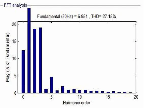
Simulated line voltage and line current wave forms of conventional PFC boost rectifier operating at 230-Vrms line voltage are shown in figure 4(b). The power factor is obtained as 0.8866. Figure4(c)shows the FFT analysis of input current wave form.
Fig 4(b) Input voltage and input current wave form
Fig.4(c)FFT analysis of input current wave form
[image:5.612.124.490.117.266.2] [image:5.612.152.437.306.518.2] [image:5.612.145.468.563.710.2]IV. BRIDGELESS PFCBOOST CONVERTER
Simulation circuit of bridgeless PFC boost converter is shown in Fig.4 (d). The controlled switch implemented is the power MOSFET which has in herentlys low body diode.
Fig4(e) Input voltage and input current wave form
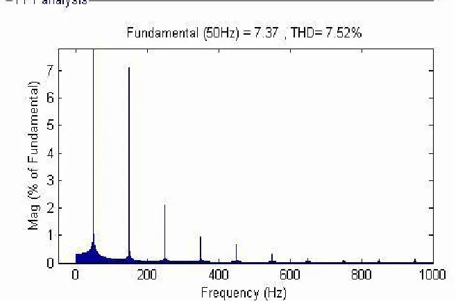
Simulated line voltage and line current wave forms of bridgeless PFC boost rectifier operating at230-Vrmsline voltage are shown in figure 4(e). The output voltage wave for miss how n in figure4 (f). FFT analysis of input current wave for miss how n in figure 4(f). The THD percentage obtained in the simulation is <10% and the power factor is obtained as 0.9332
Fig.4(f)Output voltage wave form
V. CONCLUSIONS
[image:6.612.143.473.411.628.2]REFERENCES
[1] C.M. Wang, "A novel zero-voltages witching PWM boost rectifier with high power factor and low conduction losses, "International Telecommunication Energy Conf. (INTELEC) Proc.,pp.224-229,Oct.2003
[2] S T. Erno and M.Frisch,―Second generation of PFC solutions, Power ElectronicsEurope,Issue,pp.33-35, 2004.
[3] Crbone, A. Scappatura: "A high efficiency power factor corrector for single phase bridge diode rectifier". IEEE Conf. ESC4June2004, Aachen, Germany [4] U. Moriconi, "Abridgeless PFC configuration based on L4981 PFC controller, "Application Note AN1606, ST Microelectronics, 1/18-18/18,Nov.2002. [5] L. Rossetto, G. Spiazzi, and P.Tenti,―Boost PFC with100-Hzs witching frequency providing output voltage stabilization an
[6] compliance with EMC standards, ‖IEEE Trans. Ind. Applications. vol.3 6,pp. 188–193, Jan./Feb.2000.R. Martinez and P.N.Enjeti,―A high performance single phase AC to DC rectifier within put power factor correction, ‖IEE Trans. Power Electron., vol.11, no.2, pp.311– 317, Mar.1996.
[7] H. Ye, Z. Yang, J. Dai, C. Yan, X.Xin, and J.Ying,―Common mode noise modeling and analysis of dual PFC circuit, International Telecommunication Energy Conf.(INTELEC) Proc.,pp.575-582,Sep.200
[8] Jinrong Qian; Lee, F.C.Y.:―High-efficiency single-stage single-switch high-power-factor AC/DC converter with universal input ‖IEEE Transactions on Power Electronics
[9] Lu, R. Brown, and M. Soldano,―Bridgeless PFC implementation using one cycle control technique, ‖IEEE Applied Power Electronics (APEC) Conf. Proc., pp.812-817, Mar.2005.
[10] Is mail Daut, Rosnazri Ali and Soib Taib―Design of a Single-Phase Rectifier with Improved Power Factor and Low THD using Boost Converter Technique‖
American Journal of Applied Sciences 3 7): 1902-1904,2006.
[11] M.GopinathandS.Ramareddy,―SimulationofClosedLoopControlledBridgelessPFCBoostConverter‖,JournalofTheoreticalandAppliedInformationTechnology,
2005-2009JATIT.
[12] M as wood A. I and LiuF.: A unity power factor front end rectifier with hysterias is current control, IEEE transactions on Energy Conversion, vol.21, no.1, pp.153-160.2011.