Volume 47– No.7, June 2012
ABSTRACT
In this paper a linearized Heffron-Philips model of a Single Machine Infinite Bus power system with a Fuzzy Logic Power System Stablizer (PSS) is developed. The designed fuzzy-based PSS adjusts two inputs by appropriately processing of the input angular speed and angular acceleration signal, and provides an efficient damping. The behavior of the SMIB system with & without PSS has been compared/ verified by selecting appropriate fuzzy rules with the help of simulation work carried out in MATLAB/ SIMULINK environment. The performance of the SMIB system has improved significantly compared to SMIB system without PSS. The results of the simulation show that the fuzzy PSS is more effective in damping LFO compared to conventional controllers. Further this paper investigates the design and implementation of a reduced rule fuzzy logic power system stablizer. Fuzzy controllers use a rule base to describe relationships between the input variables and output. Implementation of a detailed rule base increases in complexity as the number of input variables grow. if each input has 7 fuzzy sets, a fuzzy controller with two inputs needs 49 rules. The implementation of a controller with such a large rule base is a tedious task. We propose a reduced rule fuzzy logic power system stabilizer. The effectiveness of the reduced rule fuzzy logic power system stablizer is illustrated with simulations carried out in MATLAB.
Index Terms
Low Frequency Oscillations (LFO), Damping, Fuzzy Logic Controller (FLC), Fuzzy Set Theory, Simulink.
1.
INTRODUCTION
Low frequency electromechanical oscillations (LFO), with frequencies ranging from 0.1 to 2 Hz are inherent to electric Energy systems. The conventional controllers are designed for specific operating conditions. These stabilizers can not maintain the desired level of performance as system operating condition change. Fuzzy logic [1-4] provides a remarkably simple way to draw definite conclusions from vague, ambiguous or imprecise information. Unlike classical logic, which requires a deep understanding of a system, exact equations & precise numeric values; Fuzzy logic incorporates an alternative way of thinking. It allows modeling complex
Systems using a higher level of abstraction originating from our knowledge and experience. Fuzzy Logic controller [5-10] has proven to be a successful control approach to many complex non-linear systems [11-14] or even systems not easily amenable to analytical treatment. The paper is organized as follows; Section II describes the modelling of proposed system and its linearized model. The design of the conventional and proposed
FLC is detailed in Section III. The computer simulation results are presented and discussed in Section IV. The conclusion is mentioned in Section V. Appendix A includes various parameters of the system and controllers.
2. POWER SYSTEM MODELING
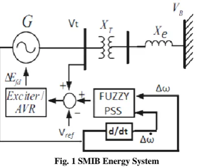
[image:1.595.325.526.349.519.2]The study system consists of a synchronous machine connected to an infinite bus through a transmission line (Fig. 1).
Fig. 1 SMIB Energy System
The fourth-order nonlinear system is described by the following set of equations.
𝛅 = 𝛚
𝛚 =𝟏
𝐌(Tm – Te – D.ω)
𝐞 𝐪′ = 𝟏 𝐓′𝐝𝟎
(Efd− 𝐞′𝐪− (𝐱𝐝− 𝐱′𝐝)𝐢𝐝)
𝐄𝐟𝐝 = 𝐓𝟏
𝐚 [𝐊𝐀(𝐕𝐫𝐞𝐟 − 𝐕𝐭)] - 𝟏 𝐓𝐚 𝐄𝐟𝐝
To calculate the parameters of Heffron-Phillips model, the fourth-order model is linearised.The linearised form of the model is:
Digital Simulation of Reduced Rule Fuzzy Logic Power
System Stabilizer for Analysis of Power System
Stability Enhancement
Vijay Kumar Tayal J. S. Lather
National Institute of Technology, National Institute of Technology,
Kurukshetra Haryana, India Kurukshetra Haryana, India
Volume 47– No.7, June 2012
∆𝛅 𝚫𝛚 𝚫𝐞 𝐪′
𝚫𝐄𝐟𝐝
=
𝟎 𝝎𝒃
−𝑲𝟏
𝑴 −𝑫𝑴
𝟎 𝟎
−𝑲𝟐
𝑴 𝟎
−𝑲𝟒
𝑻′𝒅𝟎 𝟎
−𝑲𝒂𝑲𝟓
𝐓𝐚 𝟎
−𝟏
𝑲𝟑𝐓′𝐝𝟎
𝟏 𝐓′𝐝𝟎
−𝑲𝒂𝑲𝟔
𝐓𝐚
−𝟏 𝐓𝐚
∆𝛅 ∆𝛚 ∆𝐞′𝐪
∆𝐄𝐟𝐝
+
𝟎 𝟎 𝟎 𝑲𝒂
𝐓𝐚
ΔUPSS
∆𝝎 = 𝟎 𝟏 𝟎 𝟎 ∆𝛅 ∆𝛚 ∆𝐞′𝐪
∆𝐄𝐟𝐝
[image:2.595.46.244.48.264.2]+ 𝟎 𝚫𝐔PSS
[image:2.595.324.552.72.115.2]Fig.2.shows the block diagram of Single Machine infinite bus model (SMIB). This diagram was developed by Heffron and Phillips [1952] to represent the dynamics of a single synchronous generator connected to the grid through a line. This model is a well-known model for synchronous generators. This model is a linear model; still it is quite accurate for studying low frequency oscillations and stability of power systems. It has also been successfully used for designing classical power system controllers, which are still active in most power utilities.
Fig. 2 Heffron and Phillips Model without Controller
3. CONTROLLERS
3.1 Conventional LEAD- LAG Power
System Stablizer
The basic structure of Lead-Lag controller [15-18] is shown in Fig.3. The lead - lag combination of compensators is used to achieve desired transient behavior and low steady state error. The input to controller is speed deviation (∆ω). It consists of gain block, washout block and compensator block. An optimum controller can be obtained by proper tuning of parameters Tw, T1, T2 and gain Ks with a suitable heuristic technique.
Fig. 3 Structure of conventional Power System Stablizer
[image:2.595.332.551.193.477.2]The gain Ks of conventional controller is chosen such that it provides necessary damping.
Fig. 4 MATLAB/SIMULINK Model of Plant Controlled by
conventional Power System Stablizer
The controller gain Ks is an important factor as the damping provided by the PSS increase in proportion to an increase in the gain up to a certain critical gain value, after which the damping begins to decrease. The phase compensator block is used to make the system "settle down" quickly. The output of the controller has to be gradually driven to zero in steady state. Therefore a washout transfer function [Tw.S/ (Tw.S+1)], which has a steady state gain zero is used .The value of washout time constant Tw, may be in the range of 1-20 sec. The conventional Lead-Lag controller is designed using a linearized model of the system. Therefore, this provides optimum performance for a nominal operating condition and system parameters with the input being small enough to justify the linear model. However, its performance becomes suboptimal following variations in system parameters and loading conditions from their nominal values or when the disturbance applied is large.
Delta Eq '
Delta Efd Wb / s
Wb
s
Wash out Tw.s
Tw.s+1
Transfer Fcn 1
M.s+D Speed Deviation
Power Angle Deviation
Pm
Lead -Lag T1.s+1
T2.s+1
Ka KA
Ta.s+1
K5K5
1 K4
K4
1
K3 K3
K3*Tdodash .s+1
K2 K2
1
K1 K1
1
K 6 K6
1
Gain Ks
[image:2.595.56.276.404.613.2]Volume 47– No.7, June 2012
[image:3.595.325.546.86.204.2]3.2 Fuzzy Controllers and Fuzzy Basis
Functions
Fig. 5 Basic Structure of a Fuzzy Logic Power System Stablizer
3.2.1 Design of FLC in MATLAB
Fig. 6 shows a FIS Editor with two input variable blocks, one output variable block and Mamdani FLC [19-23] block. The designing process is carried out with the help of MATLAB 7.5.
Fuzzy controllerDesign process involves 3 steps: fuzzification, fuzzy rules and defuzzification.
Fig. 6 FIS Editor FLC
3.2.2. Fuzzification
[image:3.595.49.255.97.234.2]Fuzzification process is used for converting speed and its derivative to the fuzzy values. The step defines the membership functions of controller. Seven membership functions is generating better result proved by some testing so as in Table 1, seven membership functions are defined. The linguistic labels of membership functions are marked as in fig. 7, NB (Negative Big), NM (Negative-Medium), NS (Negative-Small), ZR (Zero), PS (Positive-Small), PM (Positive-Medium), PB (Positive-Big )Membership functions are used to convert the fuzzy values between 0 and 1for inputs and output value both.
Fig. 7 Membership functions for Fuzzy controller for input and output variables
Table 1. Design Parameters of FLC
3.2.3 Fuzzy Rules
Fuzzy rules are defined to reduce the error in the system after analyzing the function of controller. For each fuzzy value there are seven membership functions, so 49 combinations of speed and acceleration are possible. There is an output for each of the membership functions and the linguistic label can be determined by using IF–THEN fuzzy rules [24] in the following form:
If speed deviation is ai and acceleration deviation is
bj then fuzzy output is cij.
[image:3.595.321.565.304.444.2] [image:3.595.47.289.391.610.2]Volume 47– No.7, June 2012
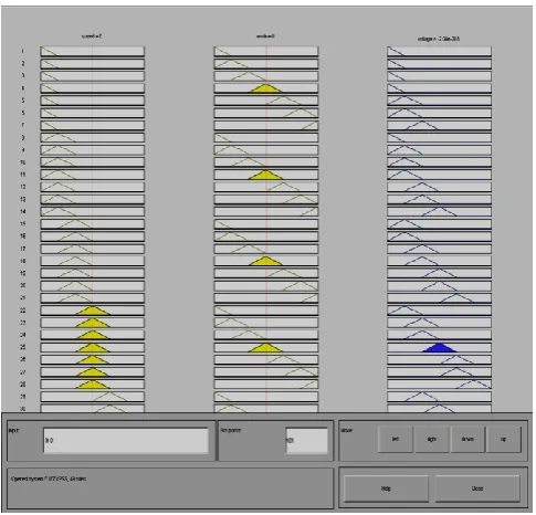
Fig. 8 Rule Viewer
3.2.4 Defuzzification
[image:4.595.48.291.48.281.2]At last Defuzzification is done. In this step the fuzzy values which are obtained from inference engine converts into the specific values. For the inference Mamdani’s minimum fuzzy implication and Max–Min compositional rule are used.
Fig. 9 MATLAB/SIMULINK Model of Plant
Controlled by FLC
[image:4.595.51.273.401.722.2]For the defuzzification centroid method is used. At first, we design a parameters satisfying FLC, according to design rules and with assumption given in previous section. Fig.9.shows the Heffron Phillips MATLAB/SIMULINK Model of Single Machine Infinite bus (SMIB) equipped with FLC.
Fig. 10 Surface Viewer
3.3 Reduced Rule Fuzzy Based Power
System Stabilizer
In previous section for a two input fuzzy controller 7 membership functions for each input were used. Due to the need for a large rule-base, the design of such a PSS is a tedious task. In the proposed fuzzy pss, only two fuzzy membership functions are used for the two inputsangular speed and acceleration and three membership functions for the output parameter are shown in Fig.11-12. Depending upon whether the output is increasing or decreasing, 4 rules were derived for the fuzzy logic controller (Table 2). These four rules are sufficient to cover all possible situations.
Fig. 11: New Reduced MFs for inputs angular speed and acceleration. N: Negative, P: Positive
Delta w
Delta Eq '
Delta Efd
Wb / s
Wb
s
Transfer Fcn
1
M.s+D
Speed Deviation
Power Angle Deviation
Pm
Ka
KA
Ta.s+1
K5
K5
1
K4
K4
1
K3
K3
K3*Tdodash .s+1
K2
K2
1
K13
K13
1
K1
K1
1
K 6
K6
1
Fuzzy Logic
Controller
Derivative 2
du/dt
Alphad
Alphad
1
Alpha
Alpha
1
-1 -0.5 0 0.5 1
0 0.2 0.4 0.6 0.8 1
ACCELERATION
D
e
g
re
e
o
f
m
e
m
b
e
rs
h
[image:4.595.326.548.573.727.2]Volume 47– No.7, June 2012
[image:5.595.320.562.86.497.2]Fig. 12: New Reduced MFs for output. N: Negative, P: Positive, Z: Zero
Table 2. Reduced rule base of a fuzzy PSS
4. SIMULATION RESULTS
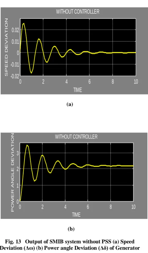
Fig.13-16 shows the output of the plant without Controller, controlled by conventional controller, FLC and Reduced Rule fuzzy pss respectively with 5% change in Mechanical input. The System parameters (a) Speed Deviation (Δω) (b) Power angle Deviation (Δδ) of Generator obtained with the proposed controllers are given in Table III.
[image:5.595.319.562.256.460.2]The Output of SMIB system without PSS (a) Speed Deviation (Δω) (b) Power angle Deviation (Δδ) of Generator are shown in Fig. 13. The above response clearly shows that system has large overshoot (Mp), large settling time (ts) & ess = 0 and ess= 2. The Output of SMIB system with conventional PSS (a) Speed Deviation (Δω) (b) Power angle Deviation (Δδ) of Generator are shown in Fig. 14. The above response shows that system has still larger overshoot (Mp), larger settling time (ts) & ess = 0 and ess= 2 for Speed Deviation and Power angle respectively .This can be further improved by fine tunning of controller parameters.
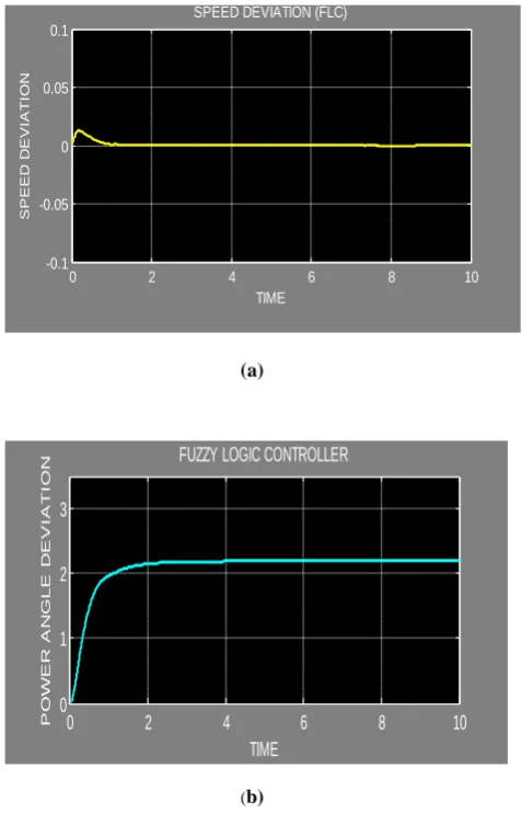
The Output of SMIB system with Fuzzy PSS (a) Speed Deviation (Δω) (b) Power angle Deviation (Δδ) of Generator are shown in Fig. 15. The above response shows that system has smaller overshoot (Mp), smaller settling time (ts) & ess = 0 and ess= 2 for Speed Deviation and Power angle respectively.
The Output of SMIB system with Reduced Rule Fuzzy PSS (a) Speed Deviation (Δω) (b) Power angle Deviation (Δδ) of Generator are shown in Fig. 16. The above response clearly shows that system has much smaller overshoot (Mp), much smaller settling time (ts) & ess = 0 for both Speed Deviation and Power angle. Therefore the proposed Fuzzy logic Power system
stabilizer with smaller rule base provides better performance comparing with the conventional power system stablizer and Fuzzy Logic Power system stabilizer .
(a)
(b)
Fig. 13 Output of SMIB system without PSS (a) Speed Deviation (Δω) (b) Power angle Deviation (Δδ) of Generator
(a)
0 0.2 0.4 0.6 0.8 1
0 0.2 0.4 0.6 0.8 1
OUTPUT
D
e
g
re
e
o
f
m
e
m
b
e
rs
h
ip
N Z P
0
2
4
6
8
10
-0.02
-0.01
0
0.01
0.02
TIME
S
P
E
E
D
D
E
V
I
A
TI
O
N
WITHOUT CONTROLLER
0 2 4 6 8 10
0 1 2 3
TIME
P
O
W
E
R
A
N
G
L
E
D
E
V
I
A
T
I
O
N WITHOUT CONTROLLER
0 2 4 6 8 10
-0.02 0 0.02 0.04 0.06 0.08
TIME
S
P
E
E
D
D
E
V
IA
T
IO
N
[image:5.595.54.269.291.428.2] [image:5.595.323.560.526.673.2]Volume 47– No.7, June 2012
[image:6.595.320.565.47.430.2](b)
Fig. 14 Output of SMIB system with conventional PSS (a) Speed Deviation (Δω) (b) Power angle Deviation (Δδ) of
Generator
(a)
[image:6.595.47.279.48.210.2](b)
Fig. 15 Output of SMIB system with Fuzzy Logic PSS (a) Speed Deviation (Δω) (b) Power angle Deviation (Δδ) of
Generator
(a)
(b)
Fig. 16 Output of SMIB system with Reduced Rule base PSS (a) Speed Deviation (Δω) (b) Power angle Deviation
[image:6.595.46.285.286.658.2](Δδ) of Generator
Table 3. System Parameters with different Controllers
S . No.
System Parameter
With Conventional
PSS Controller Fuzzy PSS Reduced Rule FUZZY PSS 1 Speed deviation (δω) large overshoot (Mp),
Peak Value= 0.025 pu, large settling
time (ts),
ess = 0
Smaller overshoot (Mp), Peak Value=
0.0125 pu, Smaller Settling time (ts),ess
= 0
Smaller Overshoot (Mp), Peak Value=
0.0125 pu, Smaller Settling time (ts),ess =
0 2 Power angle deviation (δδ) large overshoot (Mp),
Peak Value= 3.5 pu,
large settling time (ts),
ess= 2
Smaller Overshoot (Mp), Peak Value=
2.1 pu, Smaller
Settling time (ts), ess= 2
Smaller Overshoot (Mp), Peak Value=
0.4 pu, Smaller
Settling time (ts), ess = 0
5. CONCLUSION
In this paper a fuzzy based Power system stabilizer is designed. The whole work is carried out in MATLAB 7.5 (b). The proposed method is then simulated on a SMIB Energy system with FLC and conventional controller using complete state space model.TheMatlab/Simulink simulations results show that in the presence of small disturbances in the system, fuzzy controller is more effective compared to the conventional controller.The Fuzzy Logic Power system stabilizer gives gives
0 2 4 6 8 10
0 1 2 3 4 5 TIME P O W E R A N G L E D E V IA T IO N
LEAD -LAG STABLIZER
0 2 4 6 8 10
-0.1 -0.05 0 0.05 0.1 TIME S P E E D D E V IA T IO N
SPEED DEVIATION (FLC)
0 2 4 6 8 10
0 1 2 3 TIME P O W E R A N G L E D E V I A T I O
N FUZZY LOGIC CONTROLLER
0 2 4 6 8 10
-0.1 -0.05 0 0.05 0.1 TIME S P E E D D E V IA T IO N
SPEED DEVIATION (REDUCED RULES FLC)
0 1 2 3 4 5 6 7 8 9 10
-3 -2 -1 0 1 2 3 TIME S P E E D D E V I A T I O N
[image:6.595.314.569.491.700.2]Volume 47– No.7, June 2012
zero steady state error and smaller overshoot and settling time than conventional power system stablizer. The simulation results further confirms that the proposed Reduced Rule Fuzzy logic Power system stabilizer with simple design approach and smaller rule base can provide better performance comparing with the conventional power system stablizer and Fuzzy Logic Power system stabilizer .
APPENDIX
Parameter values
Generator: M= 7.0 s., D = 0, Xd=1.8, Xq=1.76, Xd ’=0.3, Tdo' = 7.2940, Wb=314
Exciter :( IEEE Type ST1): KA=200, TA=0.02 s.
6. REFERENCES
[1] L.A. Zadeh, 'Fuzzy Sets', Information and Control 8, pp. 338-353, 1965.
[2] L.A. Zadeh, 'Outline of a New Approach to the Analysis of Complex Systems and Decision Processes', IEEE Transactions on Systems, Man, and Cybernetics 3 pp 28-44, 1973.
[3] L.A. Zadeh, 'A Theory of Approximate Reasoning', In: Machine Intelligence (Eds. J.E. Hayes and L.I. Mikulich), Ellis Horwood/John Wiley & Sons, New York, pp 149-196, 1979.
[4] L.A. Zadeh, 'A Rationale for Fuzzy Control', Transactions of the ASME, Ser.ies G (USA), Journal of Dynamic Systems, Measurement and Control 94,pp 3-4, 1974.
[5] W.J.M. Kickert and H.R. Van Nauta Lemke, 'Application of a Fuzzy Controller in a Warm Water Plant', Automatica 12, pp 301-308, 1976.
[6] M. Stephens and D.W. Shimmin, 'Robust Hierarchical Expert System Based Fuzzy Logic Controller with Application to Subsea Vehicles', IEE International Conference, Control '94, pp. 276-281, 1994.
[7] R.M. Tong, M.B. Beck, and A. Latten, 'Fuzzy Control of the Activated Sludge Wastewater Treatment Process', Automatica 16, pp. 695-701, 1980.
[8] C.P. Pappis and E.H. Mamdani, 'Fuzzy Logic Control of a Traffic Junction', IEEE Transactions on Systems, Man and Cybernetics 10, pp. 707-717, 1977.
[9] W. J. M. Kickert and E. H. Mamdani, “Analysis of a fuzzy logic controller,” Fuzzy Sets Syst., vol. 1, pp. 29–44, 1978.
[10] E. H. Mamdani and S. Assilian, “An experiment in linguistic synthesis with a fuzzy logic controller,” Int. J. Man Mach. Stud., vol. 7, pp. 1–13
[11] Wen-Shyong Yu and Chih-Jen Sun, 'Fuzzy Model Based Adaptive Control for a Class of Nonlinear Systems', IEEE
Transactions on Fuzzy Systems, Vol. 9, No. 3, pp. 413-425, June 2001.
[12] E.H. Mamdani, 'Application of Fuzzy Set Theory to Control Systems: A Survey', In: Fuzzy Automata and Decision
Processes (Eds. M.M. Gupta, G.N. Saridis, and B.R. Gaines), North-Holland, Amsterdam, Netherlands, 1977.
[13] O. Yagishito, O. Itoh, and M. Sugeno, 'Application of Fuzzy Reasoning to the Water Purification Process', In: Industrial Applications of Fuzzy Control, North Holland Amsterdam, Netherlands, pp. 19-40, 1985.
[14] B.M. Chung, J.H. Oh, 'Control of Dynamic Systems Using Fuzzy Learning Algorithm',Fuzzy Sets and Systems 59, pp. 1-14, 1993.
[15] da Cruz JJ, Zanetta LC. Stabilizer design for multimachine power systems using mathematical programming. Int J Electrical Power and Energy Syst 1997; 19(8):519–23.
[16] Maslennikov VA, Ustinov SM. The optimization method for coordinated tuning of power system regulators. Proceedings of the 12th Power System Computation Conference PSCC, Dresden, 1996. p.70–75.
[17] Samarasinghe V, Pahalawaththa N. Damping of multimodal oscillations in power systems using variable structure control techniques.IEE Proc Genet Trans Distrib 1997; 144(3):323–31.
[18] Abido MA, Abdel-Magid YL. Hybridizing rule-based power system stabilizers with genetic algorithms. IEEE Trans Power Syst 1999; 14(2):600–7.
[19] P. Ramaswamy, R.M. Edwards, and K.Y. Lee, 'An Automatic Tuning Method of a Fuzzy Logic Controller for Nuclear Reactors',IEEE Transactions on Nuclear Science 40(4) pp. 1253-1262, 1993.
[20] S. Shao, 'Fuzzy Self-organizing Controller and its Application for Dynamic Processes Fuzzy Sets and Systems 26,pp.151-164, 1988.'
[21] S. Y. Yi and M. J. Chung, “Systematic design and stability analysis of a fuzzy logic controller”, Fuzzy Sets Syst., vol. 72, pp. 271–298, 1995.
[22] B. Friedland, Advanced Control System Design. Englewood Cliffs, NJ: Prentice-Hall, 1996.
[23] E. H. Mamdani, “Application of fuzzy algorithms for simple dynamic plant,” Proc. Inst. Elect. Eng., vol. 121, pp. 1585–1588, 1974.
![Fig.2.shows the block diagram of Single Machine infinite bus model (SMIB). This diagram was developed by Heffron and Phillips [1952] to represent the dynamics of a single](https://thumb-us.123doks.com/thumbv2/123dok_us/8112684.791527/2.595.46.244.48.264/diagram-machine-infinite-developed-heffron-phillips-represent-dynamics.webp)
![Fig. 6 shows a FIS Editor with two input variable blocks, one output variable block and Mamdani FLC [19-23] block](https://thumb-us.123doks.com/thumbv2/123dok_us/8112684.791527/3.595.325.546.86.204/shows-editor-input-variable-blocks-output-variable-mamdani.webp)